1
FEATURES
s
Low voltage reference: 600mV
s
Low temperature coefficient reference: 25ppm
s
Accurate 600mV reference voltage:
+6mV at T
J
=25
∞
C
s
High PSRR: 45dB at 300kHz
s
High line rejection: +1mV (V
CC
from 2.2V to 18V)
DESCRIPTION
The CAT102 is a low-voltage reference and amplifier.
Designed for the control loop of low-voltage power
supplies, the reference voltage has been designed for
600mV. Over a junction temperature from -40
∞
C to
105
∞
C the reference voltage is within 8mV of the nominal
600mV. In addition, the error amplifier output and the
supply voltage pin are on separate pins.
CAT102
Precision, Adjustable Shunt Regulator (600mV Reference)
- +1% Initial Accuracy
- SOT23 Package
s
Low supply current: 300
µ
A
s
Open collector output
s
Directly drives optocouplers
s
Compact 5-lead SOT23 package
s
Industrial temperature range: -40
∞∞
∞∞
∞
C to 85
∞∞
∞∞
∞
C
© 2003 by Catalyst Semiconductor, Inc.
Characteristics subject to change without notice
Doc. No. 4007, Rev. L
APPLICATIONS
s
SMPS control loop
s
Low temperature coefficient voltage reference
s
Power management
s
Replaces zener diodes
Power supply rejection is a high 45dB at 300kHz. The
output, OUT, can sink 20mA at a maximum saturation
voltage of 250mV.
When combined with an optocoupler, the CAT102 can
be used as an error amplifier that controls the feedback
loop in isolated low-output voltage switching power
supplies.
FUNCTIONAL DIAGRAM
PIN CONFIGURATION
s
Isolated DC-to-DC converters
s
Network, telecom and cellular base station
power supplies
s
Adjustable voltage reference
+
≠
+
≠
OUT
FB
IN
VREF
600mV
Error
Amplifier
GND
3
5
2
1
SOT23-5
TOP VIEW
IN
OUT
2
3
1
NC
5
4
FB
GND

CAT102
3
Doc. No. 4007, Rev. L
l
o
b
m
y
S
r
e
t
e
m
a
r
a
P
s
n
o
i
t
i
d
n
o
C
n
i
M
p
y
T
x
a
M
s
t
i
n
U
V
N
I
e
g
n
a
R
e
g
a
t
l
o
V
y
l
p
p
u
S
2
.
2
8
1
V
I
N
I
t
n
e
r
r
u
C
y
l
p
p
u
S
t
n
e
c
s
e
i
u
Q
V
T
U
O
V
1
=
3
.
0
5
.
0
A
m
V
B
F
d
l
o
h
s
e
r
h
T
B
F
e
g
a
t
l
o
V
e
c
n
e
r
e
f
e
R
T
J
5
2
=
C
∞
4
9
5
0
0
6
6
0
6
V
m
0
4
-
C
∞
T
<
J
5
0
1
<
C
∞
8
8
5
2
1
6
n
o
i
t
a
l
u
g
e
R
e
n
i
L
V
N
I
V
o
t
V
2
.
2
=
N
I
V
8
1
=
5
.
0
1
V
m
n
o
i
t
a
l
u
g
e
R
d
a
o
L
I
T
U
O
A
m
0
1
o
t
A
m
1
=
4
8
V
m
I
B
F
t
n
e
r
r
u
C
t
u
p
n
I
B
F
0
0
5
-
0
0
5
A
n
R
R
S
P
n
o
i
t
c
e
j
e
R
y
l
p
p
u
S
r
e
w
o
P
e
c
n
e
r
e
f
e
R
z
H
k
0
0
3
=
y
c
n
e
u
q
e
r
F
5
3
5
4
B
d
A
V
n
i
a
G
p
o
o
L
n
e
p
O
r
e
i
f
il
p
m
A
r
o
r
r
E
I
T
U
O
V
,
A
m
2
=
T
U
O
V
1
=
0
6
0
8
B
d
W
B
y
c
n
e
u
q
e
r
F
n
i
a
G
y
t
i
n
U
I
T
U
O
V
,
A
m
2
=
T
U
O
V
1
=
1
2
z
H
M
V
T
U
O
e
g
a
t
l
o
v
n
o
i
t
a
r
u
t
a
S
t
u
p
t
u
O
I
T
U
O
V
,
A
m
0
2
=
B
F
H
G
I
H
=
0
0
1
0
5
2
V
m
C
S
N
A
R
T
e
c
n
a
t
c
u
d
n
o
c
s
n
a
r
T
t
u
p
t
u
O
I
T
U
O
A
m
0
2
o
t
A
m
1
=
5
.
2
V
m
/
A
m
I
K
A
E
L
t
n
e
r
r
u
C
e
g
a
k
a
e
L
t
u
p
t
u
O
V
T
U
O
V
,
V
6
1
=
B
F
0
=
0
0
2
0
0
4
A
n
I
)
X
A
M
(
T
U
O
t
n
e
r
r
u
C
t
u
p
t
u
O
m
u
m
i
x
a
M
V
T
U
O
V
3
.
0
=
0
2
A
m
ABSOLUTE MAXIMUM RATINGS
V
IN
Voltage ........................................................... 20V
OUT Voltage ........................................................ 20V
FB Voltage ........................................................... 20V
V
IN
, OUT, FB Current ........................................ 50mA
Operating Junction Temperature ..................... 150
∞
C
Lead Soldering Temperature (10 sec) ............. 260
∞
C
Storage Temperature Range ........... -65
∞
C to +150
∞
C
ELECTRICAL CHARACTERISTICS
Electrical characteristics are guaranteed over the full operating temperature range of -40
∞
C to +85
∞
C with a junction
temperature from -40
∞
C to +105
∞
C unless otherwise specified. Ambient temperature must be de-rated based upon
power dissipation and package thermal characteristics.
1
Unless otherwise stated, test conditions are V
IN
=3V,
FB=OUT, I
OUT
=1mA.
These are stress ratings only and functional operation is not
implied. Exposure to absolute maximum ratings for prolongued
time periods may affect device reliability. All voltages are with
respect to ground.
1.
Thermal Characteristics (
JA
)
5-lead, SOT-23: 255
∞
C/W

CAT102
4
Doc. No. 4007, Rev. L
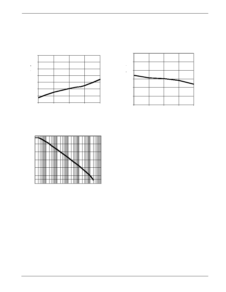
TYPICAL PERFORMANCE CHARACTERISTICS
0
0.05
0.1
0.15
0.2
0.25
0.3
0.35
0.4
2.2
6
10
14
18
0
1
2
3
4
5
6
1
5
10
15
20
Output Voltage Change (mV)
Supply Voltage (V)
Output Voltage Change (mV)
Load Current (mA)
Load Regulation
Line Regulation (at 1mA)
-100
-95
-90
-85
-80
-75
-70
-65
-60
-55
-50
0.1
1
10
100
1000
10000 100000
Supply Current (
µ
A)
100
120
140
160
180
200
220
240
260
280
300
0
5
10
15
20
Supply Current vs. Load Current
Power-Supply Rejection Ratio vs. Frequency
Load Current (mA)
Frequency (Hz)
PSRR (dB)