
1
FEATURES
s
Low startup overshoot
s
Wide current operation: 40
µ
A to 100mA
s
Low temperature coefficient reference: +12mV
max deviation over temperature
s
Accurate 1.24V reference voltage: +0.5%
(+6mV) at 25
∞∞
∞∞
∞
C
DESCRIPTION
The CAT431L is a low-voltage three-terminal
adjustable shunt voltage reference with guaranteed
thermal stability over the industrial temperature range.
The CAT431L has a lower 1.24V reference and wider
operating current range than the widely used TL431
and TL431A shunt-regulator references. Compared
to the TLV431/A, the CAT431L 1.24V reference is two
times more accurate.
CAT431L
Low-Voltage Adjustable Precision Voltage Reference
- 0.5% Tolerance
- SOT23 and TO92 Packages
- Low Startup Overshoot
s
Low dynamic impedance: 0.3
at 1kHz
s
Compact 3-lead SOT23 package option
s
Industrial temperature range: -40
∞∞
∞∞
∞
C to 85
∞∞
∞∞
∞
C
s
Adjustable output voltage: V
REF
to 6V
© 2003 by Catalyst Semiconductor, Inc.
Characteristics subject to change without notice
Doc. No. 4006, Rev. J
APPLICATIONS
s
SMPS control loop
s
Shunt regulator
s
Low temperature coefficient voltage reference
s
Current limiting
s
Over/Under voltage monitor
s
3V Off-line switching regulators
Minimal overshoot at startup and wide AC bandwidth
make the CAT431L easy to apply in a wide set of
applications. When used with an opto-coupler, the
CAT431L is an ideal voltage reference in isolated
feedback circuits for 3V to 3.3V switch-mode power
supplies.
FUNCTIONAL DIAGRAM
+
≠
VREF
REF
CATHODE
ANODE
1.24
REF
CATHODE
ANODE

CAT431L
2
Doc. No. 4006, Rev. J
PIN DESCRIPTIONS
e
m
a
N
n
i
P
n
o
i
t
c
n
u
F
H
T
A
C
l
a
m
r
o
n
r
o
f
V
4
2
.
1
n
a
h
t
r
e
t
a
e
r
g
e
b
t
s
u
m
,
l
a
n
i
m
r
e
t
y
l
p
p
u
s
d
n
a
t
u
p
t
u
O
n
o
i
t
a
r
e
p
o
F
E
R
n
o
i
t
a
r
e
p
o
l
a
m
r
o
n
n
i
V
4
2
.
1
y
ll
a
n
i
m
o
n
,
t
u
p
n
I
E
D
O
N
A
e
t
a
r
t
s
b
u
S
d
n
a
d
n
u
o
r
G
ORDERING INFORMATION
PIN CONFIGURATION
SOT-23
TOP VIEW
ANODE
CATH
2
3
1 REF
SOT-23-5
TOP VIEW
ANODE
CATH
2
3
1
REF
5
4
NC
NC
TO-92
TOP VIEW
ANODE
CATH
REF
r
e
b
m
u
N
t
r
a
P
e
g
a
k
c
a
P
e
g
n
a
R
e
r
u
t
a
r
e
p
m
e
T
t
n
e
i
b
m
A
7
E
T
-
R
U
E
L
1
3
4
T
A
C
3
2
-
T
O
S
,
n
i
P
-
3
0
4
-
∞
C
5
8
o
t
∞
C
7
E
T
-
K
U
E
L
1
3
4
T
A
C
3
2
-
T
O
S
,
n
i
P
-
5
0
4
-
∞
C
5
8
o
t
∞
C
P
A
E
T
-
R
Z
E
L
1
3
4
T
A
C
2
9
-
O
T
,
n
i
P
-
3
0
4
-
∞
C
5
8
o
t
∞
C
TE7 = 7" Reel, 3,000 parts per reel
TEAP = Ammopack, 3,000 parts per reel

CAT431L
3
Doc. No. 4006, Rev. J
ABSOLUTE MAXIMUM RATINGS
Cathode Voltage .................................................. 18V
REF Current ........................................................ 3mA
Cathode, Anode Currents ............................... 150mA
Operating Junction Temperature ..................... 150
∞
C
Lead Soldering Temperature (10 sec) ............. 260
∞
C
Storage Temperature Range ........... -65
∞
C to +150
∞
C
ELECTRICAL CHARACTERISTICS
Electrical characteristics are guaranteed over the full operating temperature range of -40
∞
C to +85
∞
C with a junction
temperature from -40
∞
C to +105
∞
C unless otherwise specified. Ambient temperature must be de-rated based upon
power dissipation and package thermal characteristics.
1
These are stress ratings only and functional operation is not
implied. Exposure to absolute maximum ratings for prolongued
time periods may affect device reliability. All voltages are with
respect to ground.
1.
Thermal Characteristics (
JA
)
3-lead, SOT-23: 336
∞
C/W
5-lead, SOT-23: 255
3-pin, TO-92: 155
l
o
b
m
y
S
r
e
t
e
m
a
r
a
P
s
n
o
i
t
i
d
n
o
C
n
i
M
p
y
T
x
a
M
s
t
i
n
U
V
F
E
R
e
g
a
t
l
o
V
e
c
n
e
r
e
f
e
R
V
F
E
R
V
=
H
T
A
C
5
2
∞
C
4
3
2
.
1
0
4
2
.
1
6
4
2
.
1
V
I
H
T
A
C
A
m
0
1
=
P
M
E
T
8
2
2
.
1
0
4
2
.
1
2
5
2
.
1
V
V
F
E
R
n
o
i
t
a
i
v
e
d
e
r
u
t
a
r
e
p
m
e
T
F
E
R
V
4
2
1
V
m
V
F
E
R
V
H
T
A
C
V
f
o
o
i
t
a
R
F
E
R
V
o
t
e
g
n
a
h
C
H
T
A
C
)
n
i
a
g
/
1
;
g
e
R
e
n
i
L
(
e
g
n
a
h
C
I
H
T
A
C
A
m
0
1
=
V
H
T
A
C
V
=
F
E
R
V
6
o
t
3
.
0
1
V
/
V
m
I
F
E
R
t
n
e
r
r
u
c
t
u
p
n
i
e
c
n
e
r
e
f
e
R
I
H
T
A
C
A
m
0
1
=
2
.
0
4
.
0
A
µ
I
F
E
R
I
F
E
R
n
o
i
t
a
i
v
e
D
e
r
u
t
a
r
e
p
m
e
T
4
0
.
0
2
.
0
A
µ
I
)
n
i
m
(
H
T
A
C
t
n
e
r
r
u
C
e
d
o
h
t
a
C
m
u
m
i
n
i
M
8
1
0
4
A
µ
I
)
F
F
O
(
H
T
A
C
t
n
e
r
r
u
C
e
d
o
h
t
a
C
e
t
a
t
S
-
f
f
O
V
F
E
R
V
;
V
0
=
H
T
A
C
V
6
1
=
0
0
1
A
n
r
H
T
A
C
e
c
n
a
d
e
p
m
I
t
u
p
t
u
O
c
i
m
a
n
y
D
I
H
T
A
C
A
m
0
0
1
o
t
1
.
0
=
z
H
k
0
.
1
=
f
3
.
0
4
.
0
Recommended Operating Conditions
r
e
t
e
m
a
r
a
P
n
i
M
x
a
M
s
t
i
n
U
e
g
a
t
l
o
V
e
d
o
h
t
a
C
F
E
R
V
6
V
t
n
e
r
r
u
C
e
d
o
h
t
a
C
1
.
0
5
1
A
m
e
r
u
t
a
r
e
p
m
e
T
t
n
e
i
b
m
A
g
n
i
t
a
r
e
p
O
0
4
-
5
8
C
∞
CAT431L
4
Doc. No. 4006, Rev. J
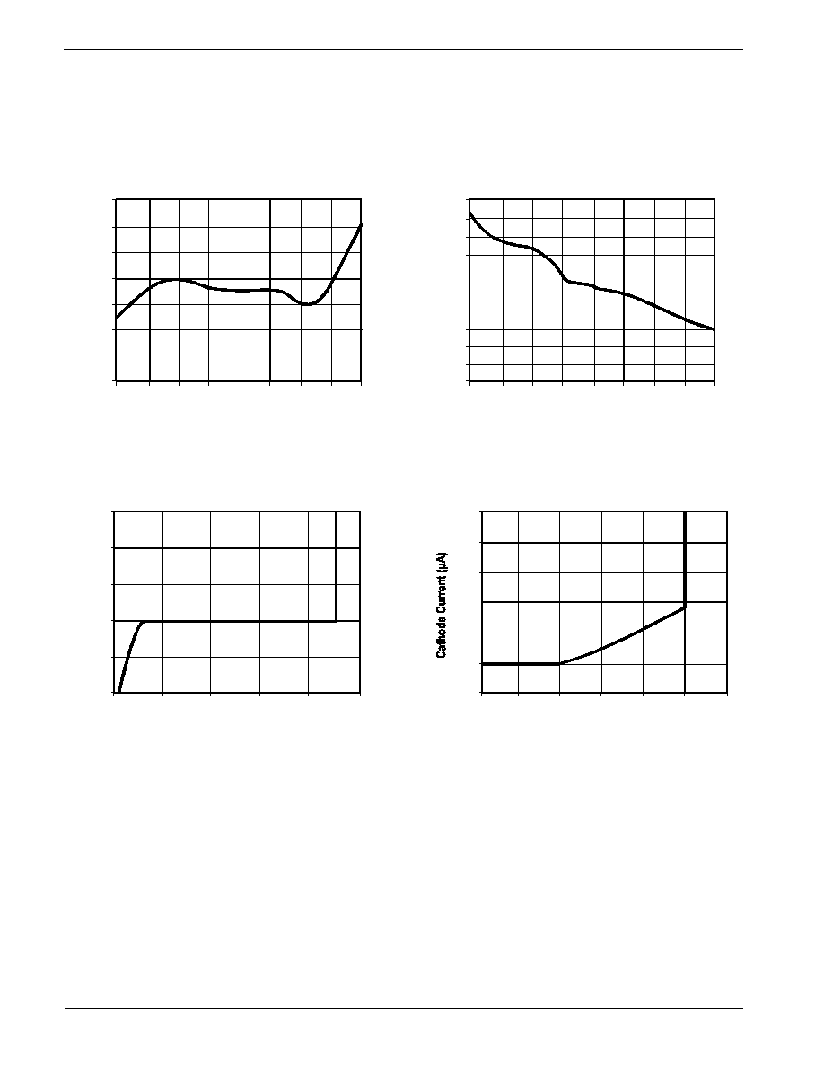
TYPICAL PERFORMANCE CHARACTERISTICS
Reference Voltage
vs.
Junction Temperature
Junction Temperature (
∞
C)
25
-50
-25
0
50
75
100
125
150
1.246
1.244
1.242
1.240
1.238
1.236
1.234
1.232
Reference
Voltage
(
V)
Reference Input Current
vs.
Junction Temperature
Junction Temperature (
∞
C)
25
-50
-25
0
50
75
100
125
150
250
240
230
220
210
200
190
180
170
160
150
Reference
Input
Current
(
nA)
Cathode Current
vs.
Cathode Voltage
Cathode Voltage (V)
0.5
-1
-0.5
0
1
1.5
150
100
50
0
-50
-100
Cathode
C
urrent
(
mA)
Cathode Current
vs.
Cathode Voltage
Cathode Voltage (V)
-1
0.5
1
1.5
50
40
30
20
10
0
-10
CAT431L
5
Doc. No. 4006, Rev. J
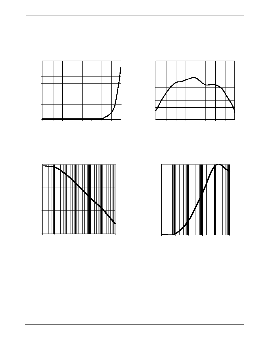
Off-State Cathode Current
vs.
Junction Temperature
Junction Temperature (
∞
C)
25
-50
-25
0
50
75
100
125
150
80
70
60
50
40
30
20
10
0
Off-State
C
athode
C
urrent
(
nA)
Delta Reference Voltage Per
Delta Cathode Voltage vs.
Junction Temperature
Junction Temperature (
∞
C)
25
-50
-25
0
50
75
100
125
150
0
-0.02
-0.04
-0.06
-0.08
-0.10
-0.12
-0.14
-0.16
-0.18
Delta
R
eference
Voltage
p
er
Delta
C
athode
Voltage
(
mV
/V)
Open Loop Voltage Gain
vs.
Frequency
Dynamic Impedance
vs.
Frequency
TYPICAL PERFORMANCE CHARACTERISTICS
-20
0
20
40
60
80
100
0.001
0.01
0.1
1
10
100
1000
0.1
1
10
100
0.1
1
10
100
1000
10000
Open Loop Voltage Gain (dB)
Dynamic Impedance (kohms)
Frequency (kHz)
Frequency (kHz)