
NE664M04
NEC's
MEDIUM POWER NPN
SILICON HIGH FRQUENCY TRANSISTOR
R57
2.05±0.1
1.25±0.1
3
1.30
1
4
2
0.65
0.65
1.25
2.0±0.1
+0.30
+0.01
-0.05
0.65
0.65
+0.40
+0.30
-0.05
(leads 1, 3 and ,4)
0.59±0.05
+0.1
1
+0.1
-0.05
∑
HIGH GAIN BANDWIDTH:
f
T
= 20 GHz
∑
HIGH OUTPUT POWER:
P
-1dB
= 26 dBm at 1.8 GHz
∑
HIGH LINEAR GAIN:
G
L
= 12 dB at 1.8 GHz
∑
LOW PROFILE M04 PACKAGE:
SOT-343 footprint, with a height of only 0.59 mm
Flat lead style for better RF performance
FEATURES
California Eastern Laboratories
DESCRIPTION
NEC's NE664M04 is fabricated using NEC's state-of-the-art
UHS0 25 GHz f
T
wafer process. With a transition frequency of
20 GHz, the NE664M04 is usable in applications from 100 MHz
to over 3 GHz. The NE664M04 provides P1dB of 26 dBm, even
with low voltage and low current, making this device an
excellent choice for the output or driver stage for mobile or fixed
wireless applications.
The NE664M04 is housed in NEC's low profile/flat lead style
"M04" package
Notes:
1. Pulsed measurement, pulse width 350 µs, duty cycle 2 %.
2. Collector to Base capacitance measured by capacitance meter(automatic balance bridge method) when emitter pin is connected to the
guard pin of capacitance meter.
3. Electronic Industrail Association of Japan
4.
MAG =
|S
21
|
|S
12
|
K - 1
).
2
(
K -
PART NUMBER
NE664M04
PACKAGE OUTLINE
M04
EIAJ
3
REGISTRATION NUMBER
2SC5754
SYMBOLS
PARAMETERS AND CONDITIONS
UNITS
MIN
TYP
MAX
I
CBO
Collector Cutoff Current at V
CB
= 5V, I
E
= 0
nA
1000
I
EBO
Emitter Cutoff Current at V
EB
= 1 V, I
C
= 0
nA
1000
h
FE
DC Current
1
Gain at V
CE
= 3 V, I
C
= 100 mA
40
60
100
P
1dB
Output Power at 1 dB compression point at V
CE
= 3.6 V, I
CQ
= 4 mA,
dBm
26.0
f = 1.8 GHz, P
in
= 15 dBm, 1/2 Duty Cycle
G
L
Linear Gain at V
CE
= 3.6 V, I
CQ
= 20 mA, f = 1.8 GHz, P
in
= 0 dBm,
dB
12.0
1/2 Duty Cycle
MAG
Maximum Available Power Gain
4
at V
CE
= 3 V, I
C
= 100 mA, f = 2 GHz
dBm
12.0
|S
21E
|
2
Insertion Power Gain at V
CE
= 3 V, I
C
= 100 mA, f = 2 GHz
dB
5.0
6.5
c
Collector Efficiency, 3.6 V, I
CQ
= 4 mA, f = 1.8 GHz, P
in
= 15 dBm,
%
60
1/2 Duty Cycle
f
T
Gain Bandwidth at V
CE
= 3 V, I
C
= 100 mA, f = 0.5 GHz
GHz
16
20
Cre
Feedback Capacitance
2
at V
CB
= 3 V, I
C
= 0, f = 1 MHz
pF
1.0
1.5
ELECTRICAL CHARACTERISTICS
(T
A
= 25∞C)
DC
RF
PIN CONNECTIONS
1. Emitter
2. Collector
3. Emitter
4. Base

Note:
1. Operation in excess of any one of these parameters may result
in permanent damage.
2. Mounted on 38 x 38 mm, t = 0.4 mm polyimide PCB.
SYMBOLS
PARAMETERS
UNITS
RATINGS
V
CBO
Collector to Base Voltage
V
13
V
CEO
Collector to Emitter Voltage
V
5.0
V
EBO
Emitter to Base Voltage
V
1.5
I
C
Collector Current
mA
500
P
T
Total Power Dissipation
2
mW
735
T
J
Junction Temperature
∞C
150
T
STG
Storage Temperature
∞C
-65 to +150
ABSOLUTE MAXIMUM RATINGS
1
(T
A
= 25∞C)
PART NUMBER
QUANTITY
NE664M04-T2-A
3k pcs./reel
ORDERING INFORMATION
SYMBOLS
PARAMETERS
UNITS RATINGS
R
th j-a
1
Junction to Ambient Resistance
1
∞C/W
170
R
th j-a
2
Junction to Ambient Resistance
2
∞C/W
570
THERMAL RESISTANCE
Note:
1. Mounted on 38 x 38 mm, t = 0.4 mm polyimide PCB.
2. Stand alone device in free air.
NE664M04
APPLICATIONS
Bluetooth Power Class 1
f = 2.4 GHz
0 dBm
13 dBm
22 dBm
NE663M04
NE664M04
T80
R57
SS Cordless Phone
f = 2.4 GHz
20 dBm
26 dBm
NE664M04
R57
DCS1800 (GSM1800) Cellular Phone
f = 1.8 GHz
5 dBm
16 dBm
25 dBm
35 dBm
NE678M04
NE664M04
NE5520379A
(MOS FET)
A 3
9Z001
R55
R57
Cordless Phone
f = 0.9 GHz
Ò3 dBm
9 dBm
25 dBm
NE68019
(3-pin TUSMM)
NE664M04
R57
T H
NE664M04
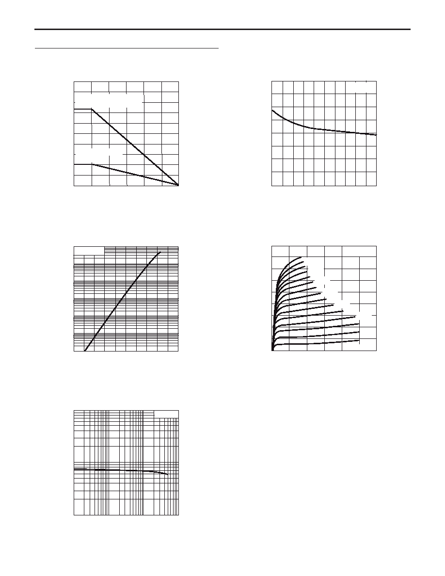
TYPICAL PERFORMANCE CURVES
(T
A
= 25∞C)
Ambient Temperature, T
A
(∫C)
Total Power Dissipation, P
tot
(mW)
TOTAL POWER DISSIPATION vs.
AMBIENT TEMPERATURE
Collector to Emitter Voltage, V
CE
(V)
COLLECTOR CURRENT vs.
COLLECTOR TO EMITTER VOLTAGE
Collector to Base Voltage, V
CB
(V)
Reverse Tramsfer Capacitance, C
re
(pF)
REVERSE TRANSFER CAPACITANCE vs.
COLLECTOR TO BASE VOLTAGE
Collector Current, I
C
(mA)
Base to Emitter Voltage, V
BE
(V)
Collector Current, I
C
(mA)
COLLECTOR CURRENT vs.
BASE TO EMITTER VOLTAGE
Collector Current, I
C
(mA)
DC Current Gain h
FE
DC CURRENT GAIN vs.
COLLECTOR CURRENT
Mounted on Polyimide PCB
(38 x 38 mm, t = 0.4 mm)
205
735
1000
600
800
400
200
0
25
50
75
100
125
150
Stand alone device
in free air
f = 1 MHz
2.0
1.5
1.0
0.5
0
1
2
3
4
5
1000
100
10
1
0.1
0.01
0.5
0.6
0.7
0.8
0.9
1.0
0.001
V
CE
= 3 V
I
B
: 0.5 mA step
I
B
= 0.5 mA
450
400
350
300
250
200
150
100
50
0
1
2
3
4
5
6
7 mA
6 mA
1 mA
2 mA
3 mA
4 mA
5 mA
1000
100
10
1
10
100
1000
V
CE
= 3 V

NE664M04
TYPICAL PERFORMANCE CURVES
(T
A
= 25∞C)
Collector Current, I
C
(mA)
Gain Bandwidth Product, f
T
(GHz)
GAIN BANDWIDTH PRODUCT vs.
COLLECTOR CURRENT
Collector Current, I
C
(mA)
INSERTION POWER GAIN, MAG, MSG
vs. COLLECTOR CURRENT
Frequency, f (Hz)
Insertion Power Gain, IS
21e
I
2
Maximum Available Gain, MAG (dB)
Maximum Stable Gain, MSG (dB)
INSERTION POWER GAIN, MAG, MSG
vs. FREQUENCY
Insertion Power Gain, IS
21e
I
2
Maximum Available Gain, MAG (dB)
Maximum Stable Gain, MSG (dB)
Collector Current, I
C
(mA)
Insertion Power Gain, IS
21e
I
2
Maximum Available Gain, MAG (dB)
Maximum Stable Gain, MSG (dB)
INSERTION POWER GAIN, MAG, MSG
vs. COLLECTOR CURRENT
Collector Current, I
C
(mA)
Insertion Power Gain, IS
21e
I
2
Maximum Available Gain, MAG (dB)
Maximum Stable Gain, MSG (dB)
INSERTION POWER GAIN, MAG, MSG
vs. COLLECTOR CURRENT
V
CE
= 3 V
f = 0.5 GHz
25
20
15
10
5
0
1
10
100
1000
V
CE
= 3 V
I
C
= 100 mA
35
30
25
20
15
10
5
0
10
1
MSG
MAG
|
S
21e
|
2
V
CE
= 3 V
f = 1 GHz
20
15
10
5
0
1
10
100
1000
MSG
MAG
|
S
21e
|
2
V
CE
= 3 V
f = 2 GHz
20
15
10
5
0
1
10
100
1000
MSG
MAG
|
S
21e
|
2
V
CE
= 3 V
f = 2.5 GHz
10
100
1000
1
0
5
10
15
20
|
S
21e
|
2
MSG
MAG

NE664M04
TYPICAL PERFORMANCE CURVES
(T
A
= 25∞C)
V
CE
= 3.2 V, f = 0.9 GHz
I
Cq
= 20 mA, 1/2 Duty
30
25
20
15
10
5
0
-15
-10
-5
0
5
10
15
G
P
I
C
P
out
c
0
50
100
150
200
250
300
V
CE
= 3.2 V, f = 2.4 GHz
I
Cq
= 20 mA, 1/2 Duty
30
25
20
15
10
5
0
-5
0
5
10
15
20
25
I
C
P
out
c
0
50
100
150
200
250
300
G
P
V
CE
= 3.2 V, f = 1.8 GHz
I
Cq
= 4 mA, 1/2 Duty
30
25
20
15
10
5
0
G
P
I
C
P
out
c
0
50
100
150
200
250
300
-10
-5
0
5
10
15
20
V
CE
= 3.2 V, f = 1.8 GHz
I
Cq
= 20 mA, 1/2 Duty
30
25
20
15
10
5
0
G
P
I
C
P
out
c
0
50
100
150
200
250
300
-10
-5
0
5
10
15
20
V
CE
= 3.6 V, f = 1.8 GHz
I
Cq
= 4 mA, 1/2 Duty
30
25
20
15
10
5
G
P
I
C
P
out
c
0
-10
-5
0
5
10
15
20
0
50
100
150
200
250
300
V
CE
= 3.6 V, f = 1.8 GHz
I
Cq
= 20 mA, 1/2 Duty
30
25
20
15
10
5
G
P
I
C
P
out
c
0
-10
-5
0
5
10
15
20
0
50
100
150
200
250
300
Input Power, P
in
(dBm)
Output Power, P
out
(dBm)
Power Gain, G
p
(dB)
Input Power, P
in
(dBm)
Output Power, P
out
(dBm)
Power Gain, G
p
(dB)
OUTPUT POWER, POWER GAIN, COLLECTOR CURRENT,
& COLLECTOR EFFICIENCY
vs. INPUT POWER
Collector Current, I
C
(mA)
Collector Efficiency,
C
(%)
OUTPUT POWER, POWER GAIN, COLLECTOR CURRENT,
& COLLECTOR EFFICIENCY
vs. INPUT POWER
Collector Current, I
C
(mA)
Collector Efficiency,
C
(%)
Input Power, P
in
(dBm)
Output Power, P
out
(dBm)
Power Gain, G
p
(dB)
Input Power, P
in
(dBm)
Output Power, P
out
(dBm)
Power Gain, G
p
(dB)
OUTPUT POWER, POWER GAIN, COLLECTOR CURRENT,
& COLLECTOR EFFICIENCY
vs. INPUT POWER
Collector Current, I
C
(mA)
Collector Efficiency,
C
(%)
OUTPUT POWER, POWER GAIN, COLLECTOR CURRENT,
& COLLECTOR EFFICIENCY
vs. INPUT POWER
Collector Current, I
C
(mA)
Collector Efficiency,
C
(%)
Input Power, P
in
(dBm)
Output Power, P
out
(dBm)
Power Gain, G
p
(dB)
Input Power, P
in
(dBm)
Output Power, P
out
(dBm)
Power Gain, G
p
(dB)
OUTPUT POWER, POWER GAIN, COLLECTOR CURRENT,
& COLLECTOR EFFICIENCY
vs. INPUT POWER
Collector Current, I
C
(mA)
Collector Efficiency,
C
(%)
OUTPUT POWER, POWER GAIN, COLLECTOR CURRENT,
& COLLECTOR EFFICIENCY
vs. INPUT POWER
Collector Current, I
C
(mA)
Collector Efficiency,
C
(%)
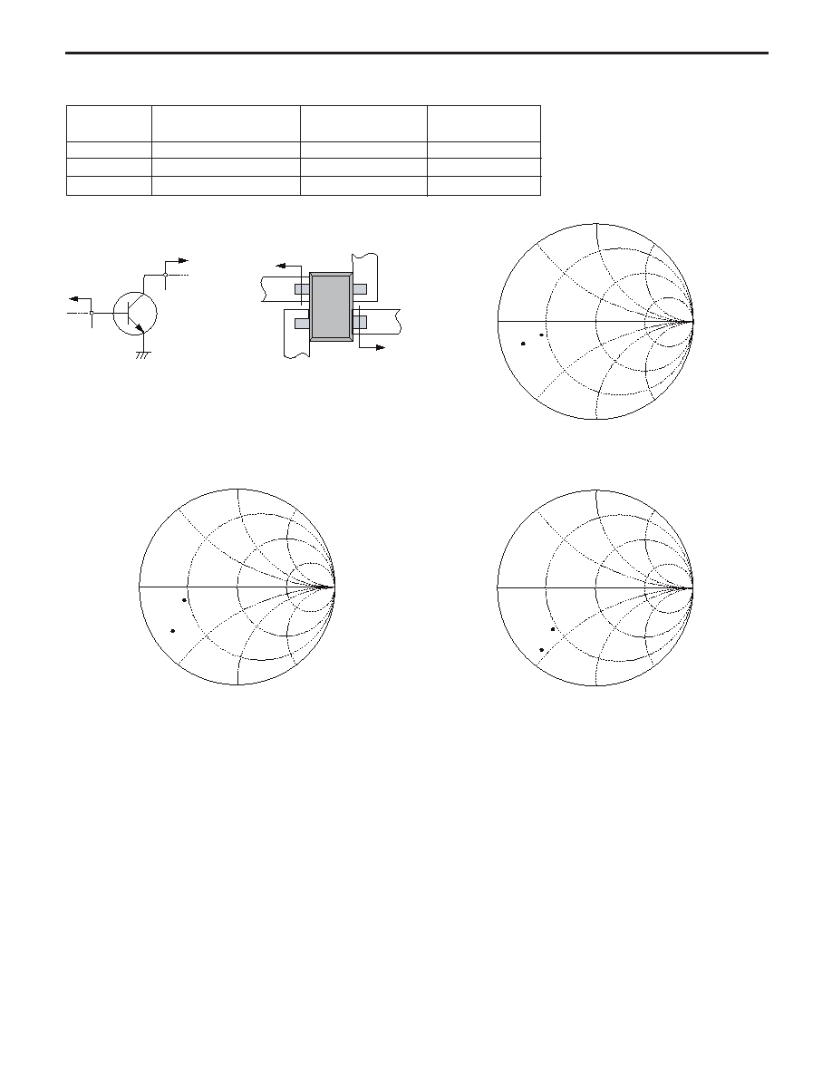
FREQUENCY
COLLECTOR TO EMITTER
SOURCE IMPEDANCE
LOAD IMPEDANCE
f (GHz)
VOLTAGE V
CE
(V)
Z
S
(
)
Z
L
(
)
0.9
2.8 to 3.6
8.4 - 5.2j
15.1- 4.3j
1.8
2.8 to 3.6
6.3 - 16.4j
15.8- 6.9j
2.4
2.8 to 3.6
5.9 - 22.1j
15.2- 17.9j
LARGE SIGNAL IMPEDANCES
Z
L
Z
L
Z
S
GND
GND
RF output line
RF input line
Z
S
Tr.
B
C
E
E
Z
S
Z
L
f = 0.9 GHz
Z
S
Z
L
Z
S
Z
L
f = 1.8 GHz
f = 2.4 GHz
NE664M04
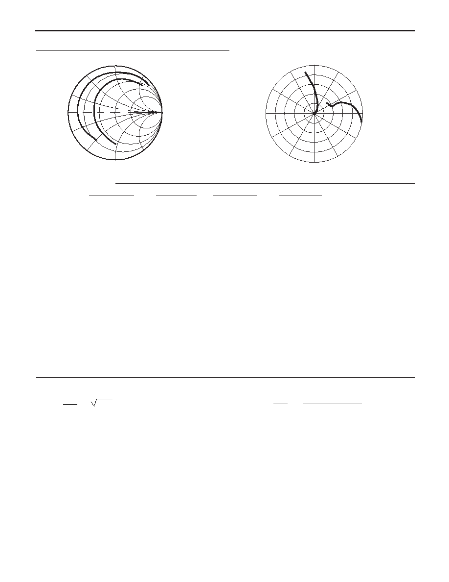
TYPICAL SCATTERING PARAMETERS
(T
A
= 25∞C)
FREQUENCY
S
11
S
21
S
12
S
22
K
MAG
1
GHz
MAG
ANG
MAG
ANG
MAG
ANG
MAG
ANG
(dB)
NE664M04
V
C
= 1 V, I
C
= 10 mA
0.50
0.784
-161.6
6.573
95.1
0.075
19.0
0.491
-138.6
0.32
19.44
1.00
0.801
178.1
3.389
77.6
0.081
16.3
0.454
-164.9
0.60
16.23
1.50
0.810
166.2
2.271
65.1
0.084
18.9
0.460
-178.3
0.85
14.33
2.00
0.812
157.2
1.710
54.4
0.090
18.1
0.467
172.5
1.03
11.77
2.50
0.820
149.0
1.378
44.3
0.097
20.8
0.476
165.3
1.16
9.14
3.00
0.827
141.5
1.163
35.2
0.109
20.6
0.482
158.0
1.20
7.60
3.50
0.834
133.6
1.013
26.1
0.119
18.7
0.498
151.0
1.22
6.47
4.00
0.838
125.9
0.901
17.1
0.133
16.2
0.508
143.9
1.22
5.49
4.50
0.845
118.0
0.816
8.6
0.146
11.6
0.525
136.4
1.19
4.84
5.00
0.850
110.4
0.743
0.1
0.160
8.6
0.546
128.9
1.17
4.15
5.50
0.855
102.3
0.678
- 7.5
0.170
5.7
0.570
121.9
1.19
3.40
6.00
0.861
95.2
0.624
- 14.9
0.175
0.9
0.599
115.4
1.18
2.93
6.50
0.866
88.6
0.573
- 21.9
0.190
- 3.9
0.625
108.6
1.15
2.44
7.00
0.874
82.3
0.530
- 28.0
0.195
- 7.7
0.650
102.4
1.14
2.05
7.50
0.881
76.5
0.485
- 34.0
0.198
- 12.6
0.676
95.6
1.14
1.58
8.00
0.889
72.0
0.451
- 38.9
0.203
- 17.2
0.696
89.6
1.13
1.29
8.50
0.898
67.3
0.422
- 44.1
0.211
- 21.6
0.716
83.0
1.09
1.14
9.00
0.905
63.5
0.391
- 48.5
0.205
- 25.6
0.733
76.4
1.11
0.76
9.50
0.911
60.2
0.360
- 52.4
0.208
- 30.2
0.740
70.9
1.11
0.34
10.00
0.916
56.1
0.337
- 56.3
0.208
- 33.9
0.768
63.4
1.12
0.01
10.50
0.917
52.2
0.321
- 60.0
0.209
- 38.7
0.782
58.1
1.12
- 0.24
11.00
0.926
48.4
0.305
- 64.1
0.210
- 42.2
0.793
53.2
1.09
- 0.27
11.50
0.923
44.4
0.295
- 66.4
0.208
- 46.5
0.811
49.2
1.11
- 0.52
12.00
0.931
40.0
0.290
- 69.9
0.221
- 50.7
0.816
46.3
1.06
- 0.27
j50
j25
j10
0
10
25
-j10
-j25
-j50
-j100
j100
0
50
100
0
S
22
S
11
0.200 to 12.000GHz by 0.100
120∞
90∞
60∞
30∞
150∞
180∞
-150∞
-120∞
-90∞
-60∞
-30∞
0∞
0.200 to 12.000GHz by 0.100
Note:
1. Gain Calculations:
MAG =
|S
21
|
|S
12
|
K - 1
).
2
(
K ±
= S
11
S
22
- S
21
S
12
When K 1, MAG is undefined and MSG values are used. MSG =
|S
21
|
|S
12
|
, K = 1 + | | - |S
11
| - |S
22
|
2
2
2
2 |S
12
S
21
|
,
MAG = Maximum Available Gain
MSG = Maximum Stable Gain
NE664M04

Note:
1. Gain Calculations:
MAG =
|S
21
|
|S
12
|
K - 1
).
2
(
K ±
= S
11
S
22
- S
21
S
12
When K 1, MAG is undefined and MSG values are used. MSG =
|S
21
|
|S
12
|
, K = 1 + | | - |S
11
| - |S
22
|
2
2
2
2 |S
12
S
21
|
,
MAG = Maximum Available Gain
MSG = Maximum Stable Gain
NE664M04
TYPICAL SCATTERING PARAMETERS
(T
A
= 25∞C)
FREQUENCY
S
11
S
21
S
12
S
22
K
MAG
1
GHz
MAG
ANG
MAG
ANG
MAG
ANG
MAG
ANG
(dB)
NE664M04
V
C
= 2 V, I
C
= 100 mA
0.50
0.808
177.3
9.415
90.1
0.027
50.0
0.652
-167.8
0.87
25.50
1.00
0.812
167.0
4.762
77.9
0.046
62.1
0.650
176.3
1.04
18.88
1.50
0.819
158.7
3.176
68.6
0.065
57.6
0.657
166.5
1.07
15.33
2.00
0.822
151.3
2.387
60.0
0.083
53.6
0.662
158.5
1.08
12.85
2.50
0.830
143.8
1.925
51.6
0.106
48.0
0.666
151.4
1.06
11.12
3.00
0.831
137.2
1.616
43.8
0.123
43.3
0.670
144.1
1.07
9.60
3.50
0.834
129.9
1.410
36.0
0.140
37.1
0.669
137.0
1.07
8.45
4.00
0.837
122.8
1.256
27.7
0.159
30.9
0.672
129.3
1.06
7.52
4.50
0.836
115.1
1.138
19.7
0.175
25.2
0.680
121.7
1.06
6.61
5.00
0.843
107.7
1.035
12.1
0.188
18.1
0.691
114.7
1.06
5.96
5.50
0.843
100.1
0.945
4.4
0.197
11.6
0.701
108.2
1.06
5.25
6.00
0.851
93.1
0.868
- 2.5
0.207
6.4
0.715
101.9
1.06
4.71
6.50
0.857
86.5
0.800
- 9.0
0.212
- 0.2
0.731
95.8
1.06
4.23
7.00
0.865
80.8
0.742
- 15.3
0.222
- 4.7
0.745
90.2
1.06
3.80
7.50
0.866
75.4
0.688
- 21.2
0.225
- 10.8
0.751
84.5
1.07
3.29
8.00
0.874
70.6
0.641
- 26.6
0.225
- 15.7
0.761
78.7
1.07
2.94
8.50
0.883
66.5
0.591
- 32.4
0.227
- 19.8
0.772
72.4
1.07
2.56
9.00
0.891
62.6
0.551
- 37.1
0.231
- 25.9
0.774
66.3
1.06
2.24
9.50
0.900
59.2
0.517
- 43.0
0.221
- 30.6
0.788
60.8
1.06
2.17
10.00
0.902
55.6
0.491
- 47.2
0.226
- 34.5
0.796
54.7
1.07
1.80
10.50
0.914
51.8
0.456
- 52.1
0.219
- 39.4
0.805
49.5
1.06
1.69
11.00
0.918
48.1
0.435
- 56.2
0.219
- 43.8
0.810
45.5
1.05
1.54
11.50
0.917
44.1
0.419
- 60.1
0.219
- 47.4
0.822
41.9
1.06
1.31
12.00
0.917
39.7
0.413
- 63.7
0.229
- 50.6
0.822
38.8
1.05
1.13
j50
j25
j10
0
10
25
-j10
-j25
-j50
-j100
j100
0
50
100
0
S
22
S
11
0.200 to 12.000GHz by 0.100
120∞
90∞
60∞
30∞
150∞
180∞
-150∞
-120∞
-90∞
-60∞
-30∞
0∞
0.200 to 12.000GHz by 0.100
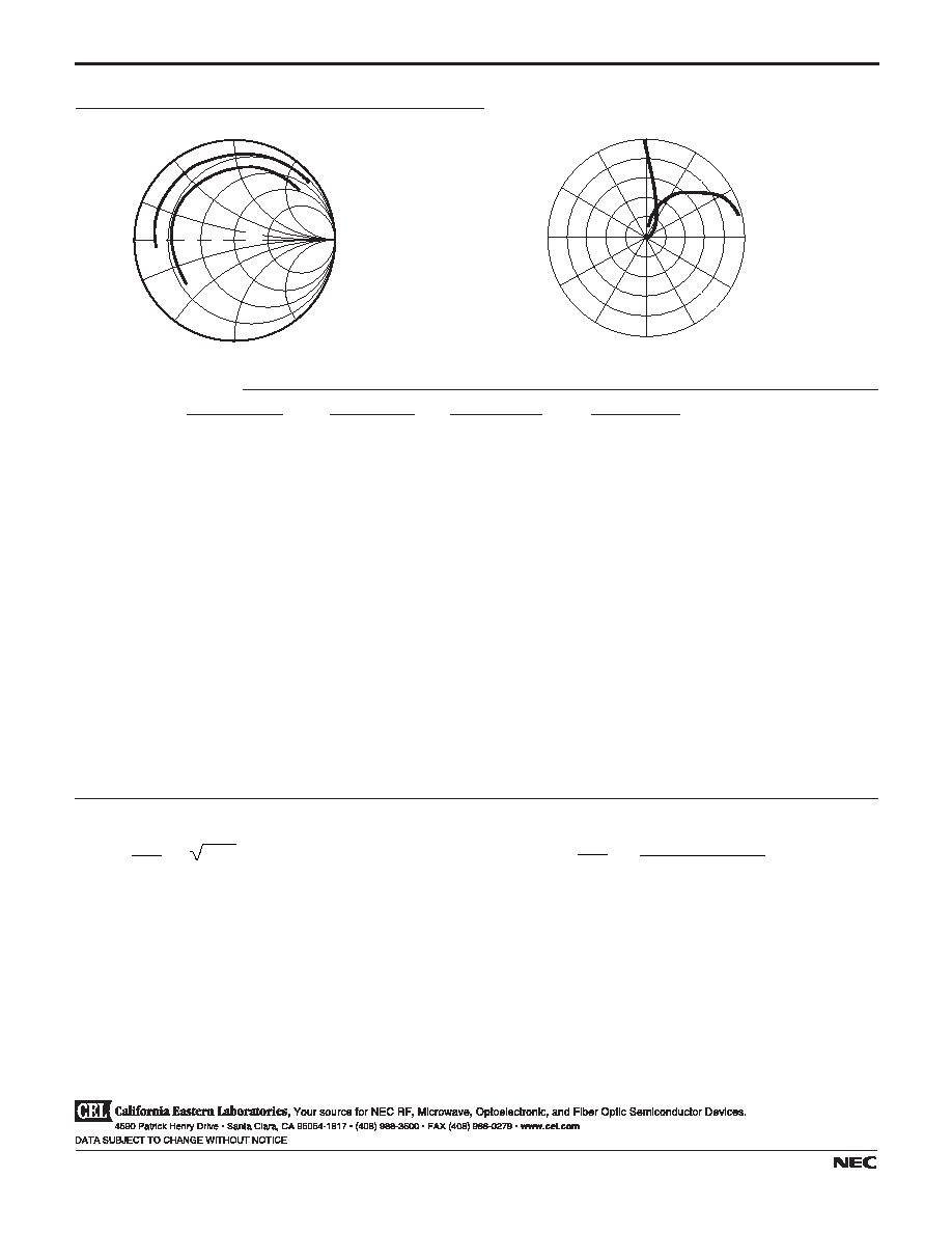
Note:
1. Gain Calculations:
MAG =
|S
21
|
|S
12
|
K - 1
).
2
(
K ±
= S
11
S
22
- S
21
S
12
When K 1, MAG is undefined and MSG values are used. MSG =
|S
21
|
|S
12
|
, K = 1 + | | - |S
11
| - |S
22
|
2
2
2
2 |S
12
S
21
|
,
MAG = Maximum Available Gain
MSG = Maximum Stable Gain
NE664M04
TYPICAL SCATTERING PARAMETERS
(T
A
= 25∞C)
FREQUENCY
S
11
S
21
S
12
S
22
K
MAG
1
GHz
MAG
ANG
MAG
ANG
MAG
ANG
MAG
ANG
(dB)
NE664M04
V
C
= 3 V, I
C
= 200 mA
0.50
0.801
175.9
9.856
89.7
0.024
66.8
0.624
-169.4
1.01
25.43
1.00
0.808
166.3
4.975
77.5
0.044
68.0
0.632
175.5
1.07
18.85
1.50
0.815
158.4
3.310
68.2
0.066
62.1
0.633
166.7
1.07
15.41
2.00
0.819
150.9
2.483
59.8
0.084
57.6
0.638
158.1
1.08
12.95
2.50
0.822
143.9
1.996
51.6
0.102
52.3
0.644
150.8
1.09
11.11
3.00
0.830
136.8
1.676
43.6
0.122
43.9
0.648
144.1
1.07
9.80
3.50
0.832
129.7
1.461
35.8
0.138
39.2
0.653
136.7
1.07
8.62
4.00
0.831
122.5
1.299
27.6
0.156
32.6
0.656
129.3
1.07
7.59
4.50
0.835
115.0
1.171
19.8
0.173
26.9
0.662
122.1
1.07
6.75
5.00
0.837
107.6
1.069
12.0
0.187
19.5
0.672
114.9
1.06
6.05
5.50
0.842
100.2
0.979
4.4
0.198
11.8
0.683
108.2
1.06
5.44
6.00
0.848
93.0
0.896
- 2.8
0.211
7.0
0.698
102.1
1.06
4.83
6.50
0.853
86.4
0.828
- 9.1
0.214
1.2
0.711
96.2
1.06
4.32
7.00
0.862
80.5
0.764
- 15.4
0.216
- 4.7
0.724
90.6
1.06
3.92
7.50
0.868
75.4
0.707
- 21.5
0.226
- 9.8
0.736
85.1
1.06
3.47
8.00
0.873
70.4
0.660
- 26.8
0.231
- 15.6
0.748
78.9
1.06
3.08
8.50
0.881
66.5
0.611
- 32.7
0.223
- 20.4
0.750
72.7
1.07
2.72
9.00
0.890
62.7
0.572
- 36.9
0.226
- 24.0
0.764
67.2
1.07
2.45
9.50
0.895
59.3
0.532
- 42.0
0.226
- 30.2
0.771
61.0
1.07
2.11
10.00
0.903
55.7
0.498
- 47.9
0.219
- 33.8
0.779
55.0
1.07
1.91
10.50
0.911
52.0
0.466
- 51.7
0.224
- 38.3
0.793
48.9
1.06
1.64
11.00
0.915
48.3
0.445
- 56.3
0.219
- 43.0
0.794
45.8
1.06
1.53
11.50
0.919
44.1
0.430
- 60.1
0.226
- 46.2
0.810
41.6
1.05
1.40
12.00
0.918
39.8
0.426
- 64.6
0.229
- 49.5
0.811
39.3
1.05
1.34
j50
j25
j10
0
10
25
-j10
-j25
-j50
-j100
j100
0
50
100
0
S
22
S
11
0.200 to 12.000GHz by 0.100
120∞
90∞
60∞
30∞
150∞
180∞
-150∞
-120∞
-90∞
-60∞
-30∞
0∞
0.200 to 12.000GHz by 0.100
Life Support Applications
These NEC products are not intended for use in life support devices, appliances, or systems where the malfunction of these products can reasonably
be expected to result in personal injury. The customers of CEL using or selling these products for use in such applications do so at their own risk and
agree to fully indemnify CEL for all damages resulting from such improper use or sale.
A Business Partner of NEC Compound Semiconductor Devices, Ltd.
04/04/2003

4590 Patrick Henry Drive
Santa Clara, CA 95054-1817
Telephone: (408) 919-2500
Facsimile: (408) 988-0279
Subject: Compliance with EU Directives
CEL certifies, to its knowledge, that semiconductor and laser products detailed below are compliant
with the requirements of European Union (EU) Directive 2002/95/EC Restriction on Use of Hazardous
Substances in electrical and electronic equipment (RoHS) and the requirements of EU Directive
2003/11/EC Restriction on Penta and Octa BDE.
CEL Pb-free products have the same base part number with a suffix added. The suffix ≠A indicates
that the device is Pb-free. The ≠AZ suffix is used to designate devices containing Pb which are
exempted from the requirement of RoHS directive (*). In all cases the devices have Pb-free terminals.
All devices with these suffixes meet the requirements of the RoHS directive.
This status is based on CEL's understanding of the EU Directives and knowledge of the materials that
go into its products as of the date of disclosure of this information.
Restricted Substance
per RoHS
Concentration Limit per RoHS
(values are not yet fixed)
Concentration contained
in CEL devices
-A
-AZ
Lead (Pb)
< 1000 PPM
Not Detected
(*)
Mercury
< 1000 PPM
Not Detected
Cadmium
< 100 PPM
Not Detected
Hexavalent Chromium
< 1000 PPM
Not Detected
PBB
< 1000 PPM
Not Detected
PBDE
< 1000 PPM
Not Detected
If you should have any additional questions regarding our devices and compliance to environmental
standards, please do not hesitate to contact your local representative.
Important Information and Disclaimer: Information provided by CEL on its website or in other communications concerting the substance
content of its products represents knowledge and belief as of the date that it is provided. CEL bases its knowledge and belief on information
provided by third parties and makes no representation or warranty as to the accuracy of such information. Efforts are underway to better
integrate information from third parties. CEL has taken and continues to take reasonable steps to provide representative and accurate
information but may not have conducted destructive testing or chemical analysis on incoming materials and chemicals. CEL and CEL
suppliers consider certain information to be proprietary, and thus CAS numbers and other limited information may not be available for
release.
In no event shall CEL's liability arising out of such information exceed the total purchase price of the CEL part(s) at issue sold by CEL to
customer on an annual basis.
See CEL Terms and Conditions for additional clarification of warranties and liability.