NEC's CW InGaAsP
MQW DFB LASER DIODE MODULE
FOR DWDM APPLICATIONS (10 mW MIN)
NX8563
SERIES
FEATURES
∑ OUTPUT POWER:
P
f
= 10 mW MIN
∑ INTERNAL THERMOELECTRIC COOLER AND ISOLATOR
∑ HERMETICALLY SEALED 14-PIN BUTTERFLY PACKAGE
∑ POLARIZATION MAINTAIN FIBER PIGTAIL
∑ AVAILABLE FOR DWDM WAVELENGTHS BASED ON
ITU-T RECOMMENDATIONS (100 GHz GRID) REFER TO
THE ORDERING INFORMATION
NEC's NX8563 Series are a 1550 nm Multiple Quantum Well
(MQW) structured Distributed Feed-Back (DFB) laser diode
with Polarization Maintain Fiber (PMF). This device is de-
signed as Continuous Wave (CW) light source and ideal for
optical transmission systems in which external modulators are
used.
This device is available for Dense Wavelenght Division Multi-
plexing (DWDM) wave lengths based on ITU-T recommenda-
tions, enabling a wide range of applications.
DESCRIPTION
California Eastern Laboratories
Notes:
1. Available for DWDM based on ITU-T recommendations. Please refer to Ordering Information.
2. Polarization state of LD is aligned parallel to the slow axis.
PART NUMBER
NX8563 Series
SYMBOLS
PARAMETERS AND CONDITIONS
UNITS
MIN
TYP
MAX
T
SET
Laser Set Temperature
∞C
20
35
V
F
Forward Voltage, P
f
= 10 mW
V
1.2
1.5
I
F
Forward Current, Pf = 10 mW
mA
70
125
I
TH
Threshold Current
mA
20
40
P
f
Optical Output Power from Fiber,
I
F
= 125 mA, T
LD
= T
SET
mW
10
p
Peak Emission Wavelength
1
, P
f
= 10 mW, CW,
nm
1527.99
ITU-T
1
1611.78
T
LD
= T
SET
v
Spectral Line Width, P
f
= 10 mW, CW, 3 dB down
MHz
1
2
SMSR
Side Mode Suppression Ratio, P
f
= 10 mW, CW
dB
33
45
RIN
Relative Intensity Noise, P
f
= 10 mW, 20 MHz to 3 GHz
dB/Hz
-150
ext
Polarization Extinction Ratio
2
, P
f
= 10 mW, CW
dB
20
ELECTRO-OPTICAL CHARACTERISTICS
(T
LD
= T
SET
, T
C
= -20 to +70∞C)

ABSOLUTE MAXIMUM RATINGS
1
(T
C
= 25∞C, unless otherwise specified)
SYMBOLS
PARAMETERS
UNITS
RATINGS
I
F
Forward Current of LD
mA
300
V
R
Reverse Voltage of LD
V
2.0
I
F
Forward Current of PD
mA
10
V
R
Reverse Voltage of PD
V
20
T
C
Operating Case Temperature
∞C
-20 to +70
T
STG
Storage Temperature
∞C
-40 to +85
T
SLD
Lead Soldering
∞C
260
Temperature (10 s)
Note:
1. Operation in excess of any one of these parameters may result
in permanent damage.
PART NUMBER
NX8563 Series
SYMBOLS
PARAMETERS AND CONDITIONS
UNITS
MIN
TYP
MAX
I
m
Monitor Current, P
f
= 10 mW, V
R
= 5 V
µA
100
2000
I
D
Dark Current, V
R
= 5 V
nA
10
1
Tracking Error, I
m
= const.
dB
0.5
ELECTRO-OPTICAL CHARACTERISTICS
(Applicable to Monitor PD: T
LD
= T
SET
, T
C
= -20 to +70∞C)
P
f
(mW)
T
LD
= T
C
= 25
∞C
(at P
f
(25
∞C) = 10 mW)
T
LD
= 25
∞C, T
C
= -20 to +70
∞C
20
0
P
f
I
m
I
m
Note:
1. = 10 log
P
f
10 mW
PART NUMBER
NX8563 Series
SYMBOLS
PARAMETERS AND CONDITIONS
UNITS
MIN
TYP
MAX
R
Thermistor Resistance, T
LD
= 25∞C
k
9.5
10.0
10.5
B
B Constant
K
3350
3450
3550
I
C
Cooler Current, T = 70 - T
set
, P
f
= 10 mW
A
1
V
C
Cooler Voltage, T = 70 - T
set
, P
f
= 10 mW
V
2
ELECTRO-OPTICAL CHARACTERISTICS
(Applicable to Thermistor and TEC: T
LD
= T
SET
, T
C
= -20 to +70∞C)
NX8563 SERIES
NX8563 SERIES
TYPICAL PERFORMANCE CURVES
(T
C
= T
SET
unless otherwise specified)
10
0
-10
-20
-30
-40
-50
-60
-70
1540
1550
1560
15.0
12.5
10.0
7.5
5.0
2.5
0
0
20
40
60
80
100
120
100
80
60
40
20
0
0
0.4
0.8
1.2
1.6
2.0
2.4
0
25
50
75
50
30
20
10
5
3
2
1
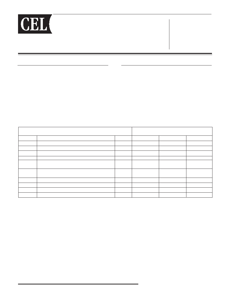
LONGITUDINAL MODE
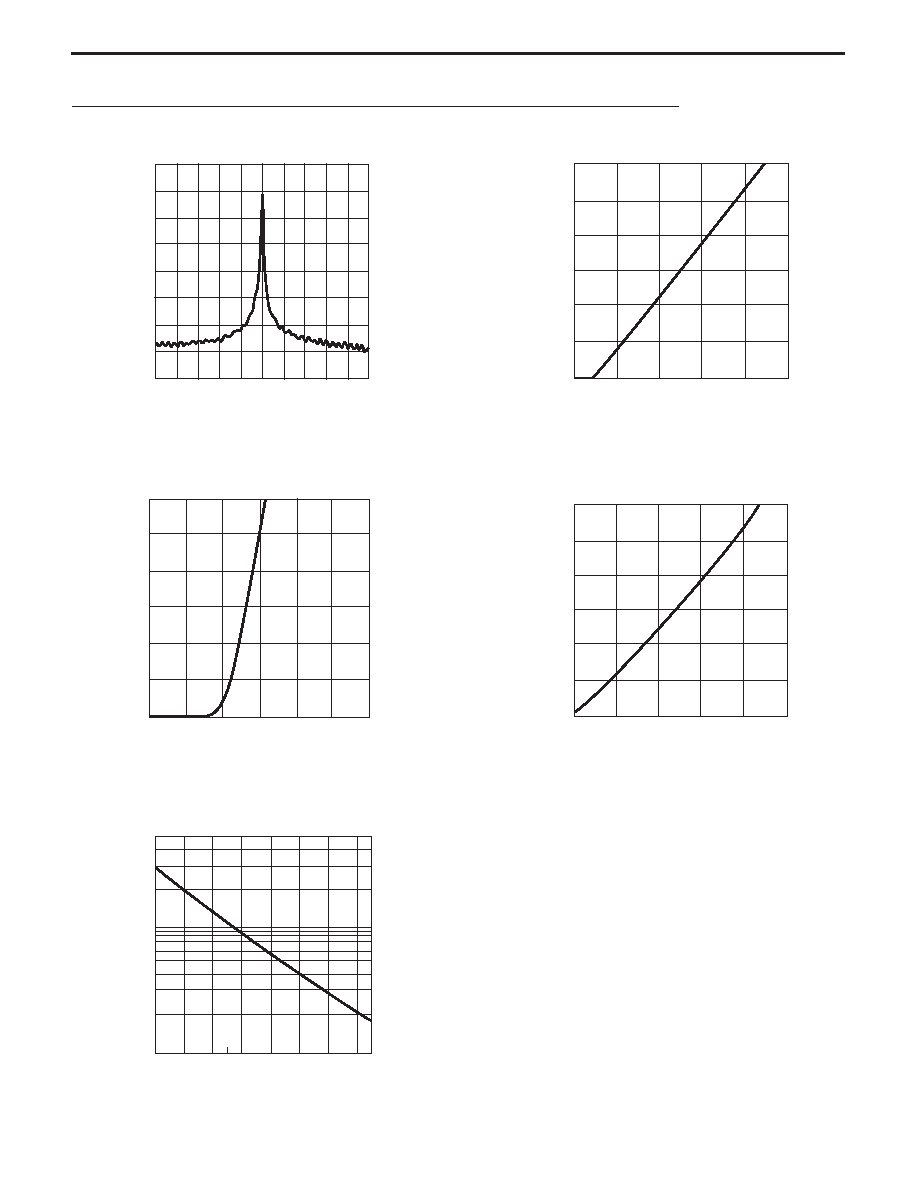
OPTICAL OUTPUT POWER FROM FIBER
vs. FORWARD CURRENT
FORWARD CURRENT vs.
FORWARD VOLTAGE
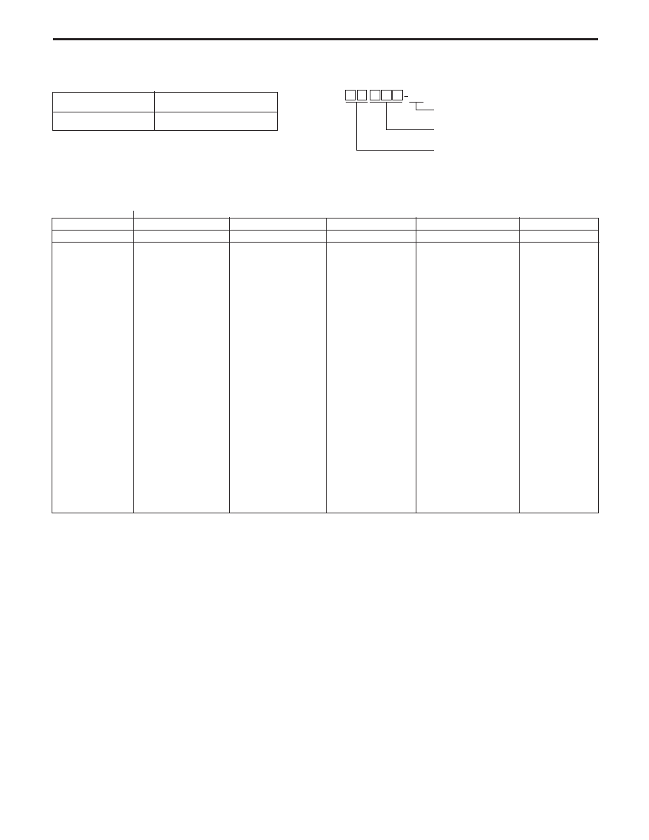
OPTICAL OUTPUT POWER FROM FIBER
vs. MONITOR CURRENT
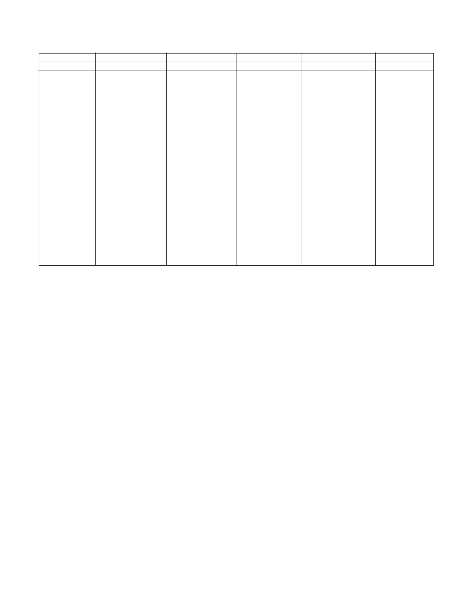
THERMISTOR RESISTANCE vs.
AMBIENT TEMPERATURE
Wavelength (nm)
Relative Intensity (dB)
Forward Current, I
F
(mA)
Optical Output Power from Fiber, P
f
(mW)
Forward Voltage, V
F
(V)
Forward Current, I
F
(mA)
Optical Output Power from Fiber, P
f
(mW)
Monitor Current, I
M
(mA)
Ambient Temperature, T
A
(∞C)
Thermistor Resistance, R (k
)
12.0
10.0
8.0
6.0
4.0
2.0
0
0
0.2
0.4
0.6
0.8
1.0
NX8563 SERIES
Wavelength code
ITU-T
1
Wavelength
Frequency
Wavelength code
ITU-T
1
Wavelength
Frequency
(nm)
(THz)
(nm)
(THz)
287
1528.77
196.10
295
1529.55
196.00
303
1530.33
195.90
311
1531.11
195.80
318
1531.89
195.70
326
1532.68
195.60
334
1533.46
195.50
342
1534.25
195.40
350
1535.03
195.30
358
1535.82
195.20
366
1536.60
195.10
373
1537.39
195.00
381
1538.18
194.90
389
1538.97
194.80
397
1539.76
194.70
405
1540.55
194.60
413
1541.34
194.50
421
1542.14
194.40
429
1542.93
194.30
437
1543.73
194.20
445
1544.52
194.10
453
1545.32
194.00
461
1546.11
193.90
469
1546.91
193.80
477
1547.71
193.70
485
1548.51
193.60
Note:
1. The Value which omitted and computed the 3rd place below the decimal point.
493
1549.31
193.50
501
1550.11
193.40
509
1550.91
193.30
517
1551.72
193.20
525
1552.52
193.10
533
1553.32
193.00
541
1554.13
192.90
549
1554.94
192.80
557
1555.74
192.70
565
1556.55
192.60
573
1557.36
192.50
581
1558.17
192.40
589
1558.98
192.30
597
1559.79
192.20
606
1560.60
192.10
614
1561.41
192.00
622
1562.23
191.90
630
1563.04
191.80
638
1563.86
191.70
646
1564.67
191.60
654
1565.49
191.50
663
1566.31
191.40
671
1567.13
191.30
679
1567.95
191.20
687
1568.77
191.10
TABLE A: DWDM Wavelength based on ITU-T Recommendations (@T
LD
= Tset)
BA
NX8563
With FC-PC Connector
Wavelength Code: Refer to Tables A and B
LB: Anode Ground
LF: Anode Floating
ORDERING INFORMATION
PART NUMBER
PACKAGE
NX8563-AZ*
14-Pin Butterrfly Package
*NOTE:
Please refer to the last page of this data sheet, "Compliance with EU Directives" for Pb-Free RoHS Compliance Infomation.
279
1527.99
196.20
Wavelength code
ITU-T
1
Wavelength
Frequency
Wavelength code
ITU-T
1
Wavelength
Frequency
(nm)
(THz)
(nm)
(THz)
695
1569.59
191.00
704
1570.41
190.90
712
1571.23
190.80
720
1572.06
190.70
728
1572.88
190.60
737
1573.71
190.50
745
1574.54
190.40
753
1575.36
190.30
761
1576.19
190.20
770
1577.02
190.10
778
1577.85
190.00
786
1578.68
189.90
795
1579.51
189.80
803
1580.35
189.70
811
1581.18
189.60
820
1582.01
189.50
828
1582.85
189.40
836
1583.69
189.30
845
1584.52
189.20
853
1585.36
189.10
862
1586.20
189.00
870
1587.04
188.90
878
1587.88
188.80
887
1588.72
188.70
895
1589.56
188.60
4904
1590.41
188.50
912
1591.25
188.40
921
1592.10
188.30
929
1592.94
188.20
937
1593.79
188.10
946
1594.64
188.00
954
1595.48
187.90
963
1596.33
187.80
971
1597.18
187.70
980
1598.04
187.60
988
1598.89
187.50
997
1599.74
187.40
6006
1600.60
187.30
6014
1601.45
187.20
6023
1602.31
187.10
6031
1603.16
187.00
6040
1604.02
186.90
6048
1604.88
186.80
6057
1605.74
186.70
6066
1606.60
186.60
6074
1607.46
186.50
6083
1608.32
186.40
6091
1609.19
186.30
6100
1610.05
186.20
6109
1610.92
186.10
6117
1611.78
186.00
TABLE B: DWDM Wavelength based on ITU-T Recommendations (@T
LD
= Tset)
Note:
1. The Value which omitted and computed the 3rd place below the decimal point.
Life Support Applications
These NEC products are not intended for use in life support devices, appliances, or systems where the malfunction of these products can reasonably be expected
to result in personal injury. The customers of CEL using or selling these products for use in such applications do so at their own risk and agree to fully indemnify
CEL for all damages resulting from such improper use or sale.
A Business Partner of NEC Compound Semiconductor Devices, Ltd.
04/02/2003
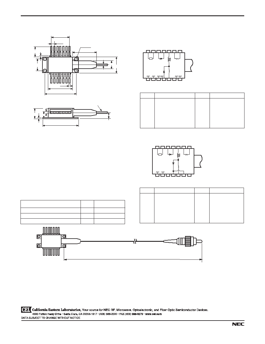
OUTLINE DIMENSIONS
(Units in mm)
#7
#1
#8
Cooler
+
-
PD
LD
Thermistor
L
#14
Optical Fiber (PMF)
Length : 1000 MIN
29.97±0.25
0.3
1.0
5.15
0.5
20.83±0.25
26.04±0.25
15.24
7
1
8
14
2.54
20.8
2.67 4 places
1.25
0.9
R
10 MIN
8.89±0.13
12.7±0.2
6.0
8.2±0.2
5.4
PIN No.
FUNCTION
PIN No.
FUNCTION
1
THERMISTOR
8
GND
2
THERMISTOR
9
GND
3
BIAS
10
GND
4
PD ANODE
11
GND, LD ANODE
5
PD CATHODE,
12
SIGNAL INPUT
6
COOLER ANODE
13
GND
7
COOLER CATHODE
14
GND
PIN CONNECTIONS
#7
#1
#8
Cooler
+
-
PD
LD
Thermistor
L
#14
R
NX8563LF
TOP VIEW
PIN No.
FUNCTION
PIN No.
FUNCTION
1
THERMISTOR
8
GND
2
THERMISTOR
9
GND
3
LD Cathode
10
PD (
p
) ANODE
4
PD (P
f
) ANODE
11
LD ANODE
5
PD CATHODE
12
LD CATHODE
6
COOLER ANODE
13
LD ANODE
7
COOLER CATHODE
14
NC
PIN CONNECTIONS
NX8563LB
TOP VIEW
OPTICAL FIBER DIMENSIONS
(Units in mm)
Paramter
Unit
Specification
Outer Diameter
mm
0.9±0.1
Minimum Fiber Bending Radius
mm
30
Fiber Length
mm
1000 MIN
Fiber Length: 1000 mm MIN
PMF
FC-PC Connector
NX8563 SERIES

4590 Patrick Henry Drive
Santa Clara, CA 95054-1817
Telephone: (408) 919-2500
Facsimile: (408) 988-0279
Subject: Compliance with EU Directives
CEL certifies, to its knowledge, that semiconductor and laser products detailed below are compliant
with the requirements of European Union (EU) Directive 2002/95/EC Restriction on Use of Hazardous
Substances in electrical and electronic equipment (RoHS) and the requirements of EU Directive
2003/11/EC Restriction on Penta and Octa BDE.
CEL Pb-free products have the same base part number with a suffix added. The suffix ≠A indicates
that the device is Pb-free. The ≠AZ suffix is used to designate devices containing Pb which are
exempted from the requirement of RoHS directive (*). In all cases the devices have Pb-free terminals.
All devices with these suffixes meet the requirements of the RoHS directive.
This status is based on CEL's understanding of the EU Directives and knowledge of the materials that
go into its products as of the date of disclosure of this information.
Restricted Substance
per RoHS
Concentration Limit per RoHS
(values are not yet fixed)
Concentration contained
in CEL devices
-A
-AZ
Lead (Pb)
< 1000 PPM
Not Detected
(*)
Mercury
< 1000 PPM
Not Detected
Cadmium
< 100 PPM
Not Detected
Hexavalent Chromium
< 1000 PPM
Not Detected
PBB
< 1000 PPM
Not Detected
PBDE
< 1000 PPM
Not Detected
If you should have any additional questions regarding our devices and compliance to environmental
standards, please do not hesitate to contact your local representative.
Important Information and Disclaimer: Information provided by CEL on its website or in other communications concerting the substance
content of its products represents knowledge and belief as of the date that it is provided. CEL bases its knowledge and belief on information
provided by third parties and makes no representation or warranty as to the accuracy of such information. Efforts are underway to better
integrate information from third parties. CEL has taken and continues to take reasonable steps to provide representative and accurate
information but may not have conducted destructive testing or chemical analysis on incoming materials and chemicals. CEL and CEL
suppliers consider certain information to be proprietary, and thus CAS numbers and other limited information may not be available for
release.
In no event shall CEL's liability arising out of such information exceed the total purchase price of the CEL part(s) at issue sold by CEL to
customer on an annual basis.
See CEL Terms and Conditions for additional clarification of warranties and liability.