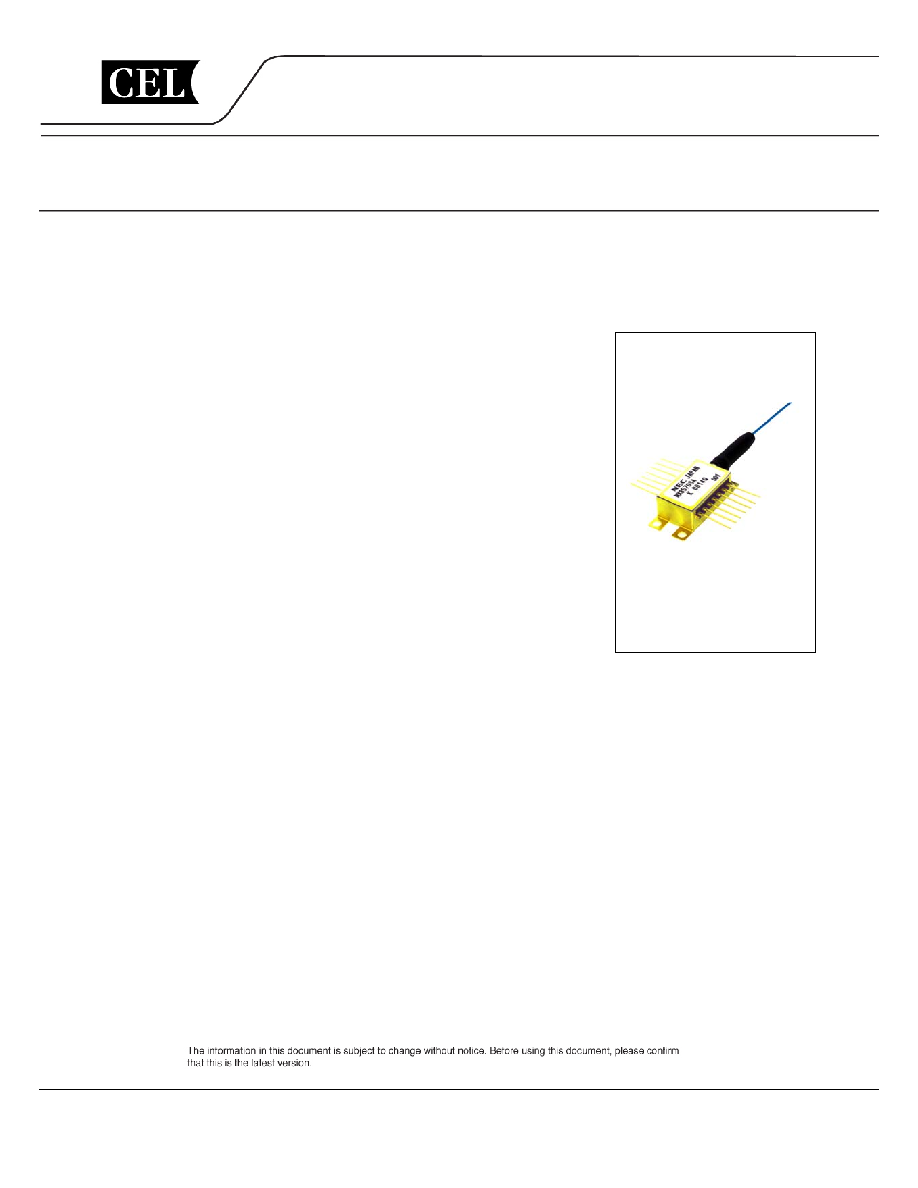
LASER DIODE
NX8570 Series
1 550 nm CW LIGHT SOURCE
InGaAsP MQW-DFB LASER DIODE MODULE
WITH WAVELENGTH MONITOR
DESCRIPTION
The NX8570 Series is a 1 550 nm Multiple Quantum Well (MQW)
structured Distributed Feed-Back (DFB) laser diode module with wavelength
monitor function. This device is temperature tunable over 4
◊
50 GHz
channels. Available at both C-band (1530.334 to 1565.087 nm) and L-band
(1565.496 to 1608.760 nm) ITU-T grid wavelengths.
This device is designed as CW light source and ideal for transmission
systems in which external modulators are used.
FEATURES
∑ Wavelength monitor function (Etalon Filter, Wavelength monitor PD)
∑ Optical output power: P
f
= 20 mW MIN.
∑ Available for DWDM wavelengths based on ITU-T recommendations
(50 GHz grid)
∑ 4-channel wavelength tunable capability for 50 GHz-spacing
(NX8570S
◊◊◊◊
D)
∑ Internal thermo-electric cooler and isolator
∑ Hermetically sealed 14-pin butterfly package
∑ Polarization maintain fiber pigtail
Document No. PL10135EJ03V0DS (3rd edition)
Date Published June 2004 CP (K)
The mark shows major revised points.
©
NEC Compound Semiconductor Devices, Ltd. 2002, 2004

NX8570 Series
PACKAGE DIMENSIONS (UNIT: mm)
29.97±0.25
8.2±0.2
5.4
5.15
0.3
1.0
Optical Fiber (PMF)
Length: 1 000 MIN.
TOP VIEW
PD (
p
)
+
≠
LD
#8
#14
#7
#1
PD (P
f
)
Cooler
Thermistor
PIN CONNECTIONS
Pin No.
Pin No.
1
2
3
4
5
6
7
8
9
10
11
12
13
14
Function
Function
Thermistor
Thermistor
LD Cathode
PD (P
f
) Anode
PD Cathode
Cooler Anode
Cooler Cathode
GND
GND
PD (
p
) Anode
LD Anode
LD Cathode
LD Anode
NC
20.83±0.25
26.04±0.25
7
8
1
14
8.89±0.13
10 MIN.
15.24
21.8±0.3
1.0
0.8
12.7±0.2
1.25
2.54
0.5
4≠ 2.67
5.0
0.9
6.0±0.2
OPTICAL FIBER CHARACTERISTICS
Parameter Specification
Unit
Outer Diameter
0.9
±
0.1 mm
Minimum Fiber Bending Radius
25
mm
Fiber Length
1 000 MIN.
mm
Fiber Length: 1 000 mm MIN.
FC-PC Connector
PMF
Data Sheet PL10135EJ03V0DS
2
NX8570 Series
ABSOLUTE MAXIMUM RATINGS
Parameter Symbol
Ratings
Unit
Forward Current of LD
I
F
300 mA
Reverse Voltage of LD
V
R
2.0 V
Forward Current of PD
I
F
10 mA
Reverse Voltage of PD
V
R
20 V
Operating Case Temperature
T
C
-
20 to +70
∞
C
Storage Temperature
T
stg
-
40 to +85
∞
C
Lead Soldering Temperature
T
sld
260 (10 sec.)
∞
C
ELECTRO-OPTICAL CHARACTERISTICS (T
LD
= T
set
, T
C
=
-
5 to +70
∞
C, unless otherwise specified)
Parameter Symbol Conditions MIN.
TYP.
MAX.
Unit
Laser Set Temperature
T
set
Single
channel
20 35
∞
C
4 channel tunable
10
45
Forward Voltage
V
F
P
f
= 20 mW
0.9
1.2
2.5
V
Threshold Current
I
th
20 40 mA
Operation Current
I
op
P
f
= 20 mW
120
167
mA
Optical Output Power from Fiber
P
f
I
F
= 167 mA, T
LD
= T
set
20
mW
Peak Emission Wavelength
p
P
f
= 20 mW, CW, T
LD
= T
set
1
530
ITU-T
*1
1 609
nm
Wevelength Stability
-
T
LD
= T
set
, applicable to wavelength
monitor, E.O.L
-
20 +20
pm
Spectral Line Width
P
f
= 20 mW, CW, 3 dB down
1
2
MHz
Side Mode Suppression Ratio
SMSR
P
f
= 20 mW, CW
35
45
dB
Relative Intensity Noise
RIN
P
f
= 20 mW, 20 MHz to 3 GHz
-
150 dB/Hz
Optical Isolation
I
s
P
f
= 20 mW, CW
30
dB
Polarization Extinction Ratio
*2
ext P
f
= 20 mW, CW
20
dB
*1 Available for DWDM wavelengths based on ITU-T recommendations (50 GHz grid).
Please refer to Table A.
*2 Polarization state of LD is aligned parallel to the slow axis.
Data Sheet PL10135EJ03V0DS
3
NX8570 Series
ELECTRO-OPTICAL CHARACTERISTICS (Applicable to Monitor PD: T
LD
= T
set
, T
C
=
-
5 to +70
∞
C)
Parameter Symbol Conditions MIN.
TYP.
MAX.
Unit
Monitor Current (P
f
Monitor)
I
m
(P
f
) P
f
= 20 mW, V
R
= 5 V
30
300
µ
A
Monitor Current (
p
Monitor)
I
m
(
p
) P
f
= 20 mW, V
R
= 5 V, Locking point
15
150
µ
A
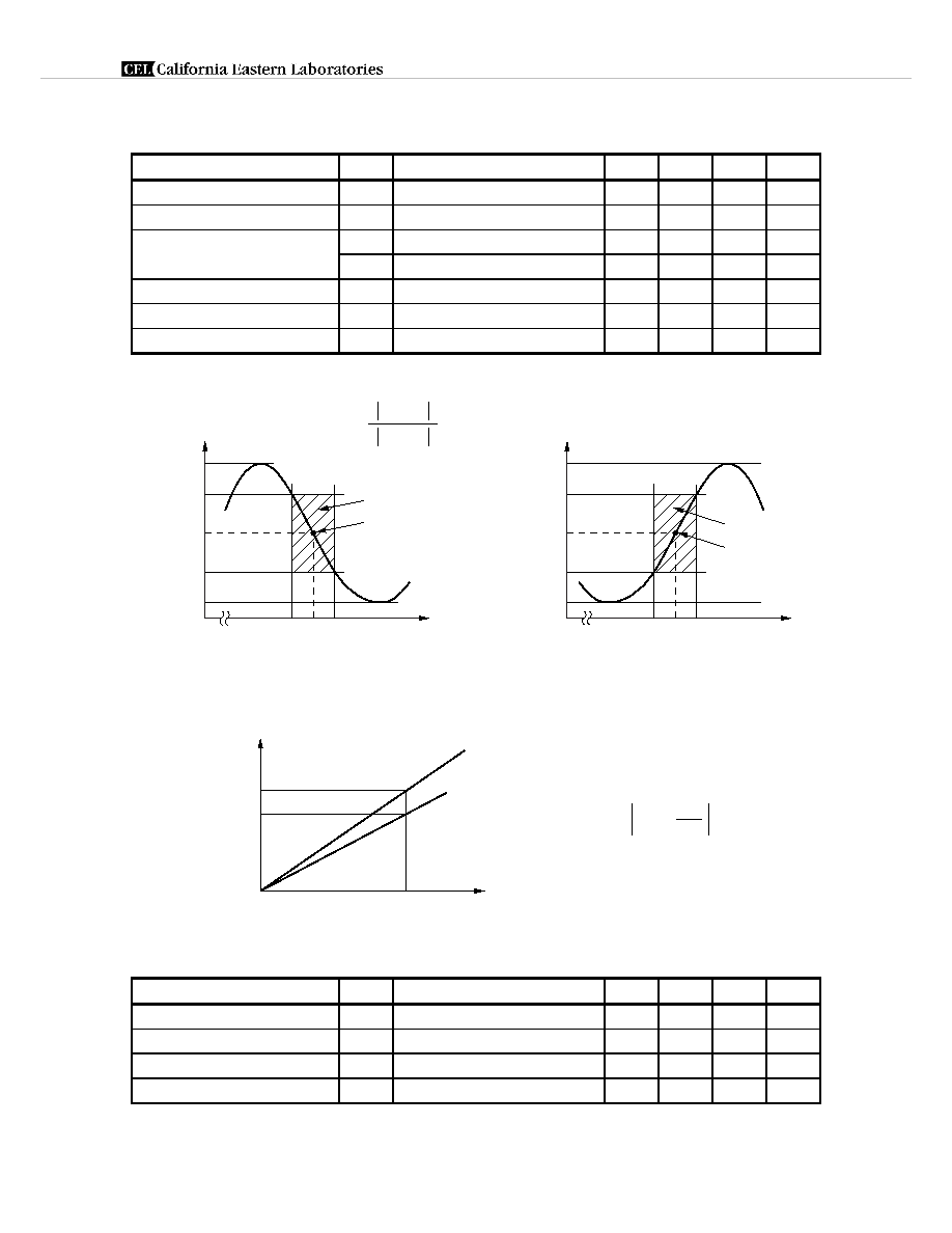
Operation Region
*1
I
m
(
)
25 75 %
1
-
2
90
pm
Discrimination Slope
*1
0.05
µ
A/pm
Dark Current
I
D
V
R
= 5 V
2
10
nA
Tracking Error
*2
I
m
= const.
0.5
dB
*1 Operation region, Discrimination slope, Slope assignment
0
I
m
(
)
I
m
@100%
I
m
(
p
)
I
m
@0%
I
1
: I
m
@75%
I
2
: I
m
@25%
1
2
p
Locking point
Negative Slope (Odd channel)
Operation region
0
I
m
(
)
I
m
@100%
I
m
(
p
)
I
m
@0%
I
2
: I
m
@75%
I
1
: I
m
@25%
1
2
p
Locking point
Positive Slope (Even channel)
Operation region
1
≠
2
I
1
≠ I
2
= [ A/pm]
µ
*2 Tracking Error:
P
f
(mW)
0
I
m
I
m
T
LD
= T
set
T
LD
= T
set
, T
C
= ≠5 to +70∞C
20
P
f
= 10 log
[dB]
P
f
20
ELECTRO-OPTICAL CHARACTERISTICS
(Applicable to Thermistor and TEC: T
LD
= T
set
, T
C
=
-
5 to +70
∞
C)
Parameter Symbol Conditions MIN.
TYP.
MAX.
Unit
Thermistor Resistance
R
T
LD
= 25
∞
C 9.5
10.0
10.5
k
B Constant
B
T
LD
= 25
∞
C
3 350
3 450
3 550
K
Cooler Current
I
C
T = 70
-
T
set
, P
f
= 20 mW
1.5
A
Cooler Voltage
V
C
T = 70
-
T
set
, P
f
= 20 mW
3.0
V
Data Sheet PL10135EJ03V0DS
4
NX8570 Series
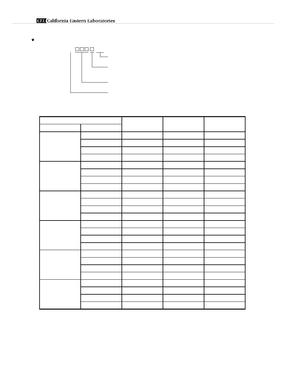
ORDERING INFORMATION
NX8570SC
-BA
With FC-PC connector
Without : Single channel
D
: 4 channel tunable
Package code
Wavelength code : Refer to Table A
Table A: DWDM wavelength base on ITU-T recommendations (@ T
LD
= T
set
) (1/7)
Wavelength Code
ITU-T Wavelength
*1
Frequency Monitor
Slope
4 channel tunable
single channel (nm)
(THz)
315D 303
1530.33
195.90
Negative
307
1530.72
195.85
Positive
311
1531.11
195.80
Negative
315
1531.50
195.75
Positive
330D 318
1531.89
195.70
Negative
322
1532.29
195.65
Positive
326
1532.68
195.60
Negative
330
1533.07
195.55
Positive
346D 334
1533.46
195.50
Negative
338
1533.85
195.45
Positive
342
1534.25
195.40
Negative
346
1534.64
195.35
Positive
362D 350
1535.03
195.30
Negative
354
1535.42
195.25
Positive
358
1535.82
195.20
Negative
362
1536.21
195.15
Positive
377D 366
1536.60
195.10
Negative
370
1537.00
195.05
Positive
373
1537.39
195.00
Negative
377
1537.79
194.95
Positive
393D 381
1538.18
194.90
Negative
385
1538.58
194.85
Positive
389
1538.97
194.80
Negative
393
1539.37
194.75
Positive
*1 The value which omitted and computed the 3rd place below the decimal point
Data Sheet PL10135EJ03V0DS
5

NX8570 Series
Table A: DWDM wavelength base on ITU-T recommendations (@ T
LD
= T
set
) (2/7)
Wavelength Code
ITU-T Wavelength
*1
Frequency Monitor
Slope
4 channel tunable
single channel (nm)
(THz)
409D 397
1539.76
194.70
Negative
401
1540.16
194.65
Positive
405
1540.55
194.60
Negative
409
1540.95
194.55
Positive
425D 413
1541.34
194.50
Negative
417
1541.74
194.45
Positive
421
1542.14
194.40
Negative
425
1542.53
194.35
Positive
441D 429
1542.93
194.30
Negative
433
1543.33
194.25
Positive
437
1543.73
194.20
Negative
441
1544.12
194.15
Positive
457D 445
1544.52
194.10
Negative
449
1544.92
194.05
Positive
453
1545.32
194.00
Negative
457
1545.72
193.95
Positive
473D 461
1546.11
193.90
Negative
465
1546.51
193.85
Positive
469
1546.91
193.80
Negative
473
1547.31
193.75
Positive
489D 477
1547.71
193.70
Negative
481
1548.11
193.65
Positive
485
1548.51
193.60
Negative
489
1548.91
193.55
Positive
505D 493
1549.31
193.50
Negative
497
1549.71
193.45
Positive
501
1550.11
193.40
Negative
505
1550.51
193.35
Positive
521D 509
1550.91
193.30
Negative
513
1551.31
193.25
Positive
517
1551.72
193.20
Negative
521
1552.12
193.15
Positive
*1 The value which omitted and computed the 3rd place below the decimal point
Data Sheet PL10135EJ03V0DS
6

NX8570 Series
Table A: DWDM wavelength base on ITU-T recommendations (@ T
LD
= T
set
) (3/7)
Wavelength Code
ITU-T Wavelength
*1
Frequency Monitor
Slope
4 channel tunable
single channel (nm)
(THz)
537D 525
1552.52
193.10
Negative
529
1552.92
193.05
Positive
533
1553.32
193.00
Negative
537
1553.73
192.95
Positive
553D 541
1554.13
192.90
Negative
545
1554.53
192.85
Positive
549
1554.94
192.80
Negative
553
1555.34
192.75
Positive
569D 557
1555.74
192.70
Negative
561
1556.15
192.65
Positive
565
1556.55
192.60
Negative
569
1556.95
192.55
Positive
585D 573
1557.36
192.50
Negative
577
1557.76
192.45
Positive
581
1558.17
192.40
Negative
585
1558.57
192.35
Positive
602D 589
1558.98
192.30
Negative
593
1559.38
192.25
Positive
597
1559.79
192.20
Negative
602
1560.20
192.15
Positive
618D 606
1560.60
192.10
Negative
610
1561.01
192.05
Positive
614
1561.41
192.00
Negative
618
1561.82
191.95
Positive
634D 622
1562.23
191.90
Negative
626
1562.64
191.85
Positive
630
1563.04
191.80
Negative
634
1563.45
191.75
Positive
650D 638
1563.86
191.70
Negative
642
1564.27
191.65
Positive
646
1564.67
191.60
Negative
650
1565.08
191.55
Positive
*1 The value which omitted and computed the 3rd place below the decimal point
Data Sheet PL10135EJ03V0DS
7

NX8570 Series
Table A: DWDM wavelength base on ITU-T recommendations (@ T
LD
= T
set
) (4/7)
Wavelength Code
ITU-T Wavelength
*1
Frequency Monitor
Slope
4 channel tunable
single channel (nm)
(THz)
667D 654
1565.49
191.50
Negative
659
1565.90
191.45
Positive
663
1566.31
191.40
Negative
667
1566.72
191.35
Positive
683D 671
1567.13
191.30
Negative
675
1567.54
191.25
Positive
679
1567.95
191.20
Negative
683
1568.36
191.15
Positive
700D 687
1568.77
191.10
Negative
691
1569.18
191.05
Positive
695
1569.59
191.00
Negative
700
1570.00
190.95
Positive
716D 704
1570.41
190.90
Negative
708
1570.82
190.85
Positive
712
1571.23
190.80
Negative
716
1571.65
190.75
Positive
733D 720
1572.06
190.70
Negative
724
1572.47
190.65
Positive
728
1572.88
190.60
Negative
733
1573.30
190.55
Positive
749D 737
1573.71
190.50
Negative
741
1574.12
190.45
Positive
745
1574.54
190.40
Negative
749
1574.95
190.35
Positive
766D 753
1575.36
190.30
Negative
757
1575.78
190.25
Positive
761
1576.19
190.20
Negative
766
1576.61
190.15
Positive
782D 770
1577.02
190.10
Negative
774
1577.44
190.05
Positive
778
1577.85
190.00
Negative
782
1578.27
189.95
Positive
*1 The value which omitted and computed the 3rd place below the decimal point
Data Sheet PL10135EJ03V0DS
8

NX8570 Series
Table A: DWDM wavelength base on ITU-T recommendations (@ T
LD
= T
set
) (5/7)
Wavelength Code
ITU-T Wavelength
*1
Frequency Monitor
Slope
4 channel tunable
single channel (nm)
(THz)
799D 786
1578.68
189.90
Negative
791
1579.10
189.85
Positive
795
1579.51
189.80
Negative
799
1579.93
189.75
Positive
816D 803
1580.35
189.70
Negative
807
1580.76
189.65
Positive
811
1581.18
189.60
Negative
816
1581.60
189.55
Positive
832D 820
1582.01
189.50
Negative
824
1582.43
189.45
Positive
828
1582.85
189.40
Negative
832
1583.27
189.35
Positive
849D 836
1583.69
189.30
Negative
841
1584.10
189.25
Positive
845
1584.52
189.20
Negative
849
1584.94
189.15
Positive
866D 853
1585.36
189.10
Negative
857
1585.78
189.05
Positive
862
1586.20
189.00
Negative
866
1586.62
188.95
Positive
883D 870
1587.04
188.90
Negative
874
1587.46
188.85
Positive
878
1587.88
188.80
Negative
883
1588.30
188.75
Positive
899D 887
1588.72
188.70
Negative
891
1589.14
188.65
Positive
895
1589.56
188.60
Negative
899
1589.98
188.55
Positive
916D 904
1590.41
188.50
Negative
908
1590.83
188.45
Positive
912
1591.25
188.40
Negative
916
1591.67
188.35
Positive
*1 The value which omitted and computed the 3rd place below the decimal point
Data Sheet PL10135EJ03V0DS
9

NX8570 Series
Table A: DWDM wavelength base on ITU-T recommendations (@ T
LD
= T
set
) (6/7)
Wavelength Code
ITU-T Wavelength
*1
Frequency Monitor
Slope
4 channel tunable
single channel (nm)
(THz)
933D 921
1592.10
188.30
Negative
925
1592.52
188.25
Positive
929
1592.94
188.20
Negative
933
1593.36
188.15
Positive
950D 937
1593.79
188.10
Negative
942
1594.21
188.05
Positive
946
1594.64
188.00
Negative
950
1595.06
187.95
Positive
967D 954
1595.48
187.90
Negative
959
1595.91
187.85
Positive
963
1596.33
187.80
Negative
967
1596.76
187.75
Positive
984D 971
1597.18
187.70
Negative
976
1597.61
187.65
Positive
980
1598.04
187.60
Negative
984
1598.46
187.55
Positive
6001D 988 1598.89
187.50
Negative
993
1599.32
187.45
Positive
997
1599.74
187.40
Negative
6001
1600.17
187.35
Positive
6018D 6006 1600.60
187.30
Negative
6010
1601.02
187.25
Positive
6014
1601.45
187.20
Negative
6018
1601.88
187.15
Positive
6035D 6023 1602.31
187.10
Negative
6027
1602.74
187.05
Positive
6031
1603.16
187.00
Negative
6035
1603.59
186.95
Positive
6053D 6040 1604.02
186.90
Negative
6044
1604.45
186.85
Positive
6048
1604.88
186.80
Negative
6053
1605.31
186.75
Positive
*1 The value which omitted and computed the 3rd place below the decimal point
Data Sheet PL10135EJ03V0DS
10
NX8570 Series
Table A: DWDM wavelength base on ITU-T recommendations (@ T
LD
= T
set
) (7/7)
Wavelength Code
ITU-T Wavelength
*1
Frequency Monitor
Slope
4 channel tunable
single channel (nm)
(THz)
6070D 6057 1605.74
186.70
Negative
6061
1606.17
186.65
Positive
6066
1606.60
186.60
Negative
6070
1607.03
186.55
Positive
6087D 6074 1607.46
186.50
Negative
6078
1607.89
186.45
Positive
6083
1608.32
186.40
Negative
6087
1608.76
186.35
Positive
*1 The value which omitted and computed the 3rd place below the decimal point
Data Sheet PL10135EJ03V0DS
11

NX8570 Series
TYPICAL CHARACTERISTICS (T
LD
= 25
∞
C, unless otherwise specified)
Forward Current I
F
(mA)
T
C
= 70∞C
Thermistor Resistance R (k
)
Cooler Electric Power Consumption (W)
50
30
20
10
1
2
3
5
0
25
50
75
15
10
20
25
30
35
SPECTRUM
Relative Intensity (dB)
Wavelength
(nm)
OPTICAL OUTPUT POWER FROM FIBER, MONITOR
CURRENT (P
f
MONITOR) vs. FORWARD CURRENT
Optical Output Power from Fiber P
f
(mW)
THERMISTOR RESISTANCE vs.
AMBIENT TEMPERATURE
COOLER ELECTRIC POWER CONSUMPTION
vs. LASER SET TEMPERATURE
Ambient Temperature T
A
(∞C)
Laser Set Temperature T
set
(∞C)
≠10
≠30
≠50
≠70
0
≠20
≠40
≠60
1 529.1
1 539.1
1 549.1
1 534.1
1 544.1
≠80
30.0
25.0
20.0
15.0
10.0
5.0
4.0
3.5
3.0
2.5
2.0
1.5
1.0
0.5
0.0
0
50
100
150
200
0.30
0.25
0.20
0.15
0.10
0.05
0
P
f
I
m
(P
f
)
Monitor Current (P
f
Monitor) I
m
(P
f
) (mA)
Remark The graphs indicate nominal characteristics.
Data Sheet PL10135EJ03V0DS
12

NX8570 Series
REFERENCE
Document Name
Document No.
OPTICAL SEMICONDUCTOR DEVICES FOR FIBEROPTIC COMMUNICATIONS SELECTION GUIDE
PL10161E
Opto-Electronics Devices Pamphlet
PX10160E
Data Sheet PL10135EJ03V0DS
13

4590 Patrick Henry Drive
Santa Clara, CA 95054-1817
Telephone: (408) 919-2500
Facsimile: (408) 988-0279
Subject: Compliance with EU Directives
CEL certifies, to its knowledge, that semiconductor and laser products detailed below are compliant
with the requirements of European Union (EU) Directive 2002/95/EC Restriction on Use of Hazardous
Substances in electrical and electronic equipment (RoHS) and the requirements of EU Directive
2003/11/EC Restriction on Penta and Octa BDE.
CEL Pb-free products have the same base part number with a suffix added. The suffix ≠A indicates
that the device is Pb-free. The ≠AZ suffix is used to designate devices containing Pb which are
exempted from the requirement of RoHS directive (*). In all cases the devices have Pb-free terminals.
All devices with these suffixes meet the requirements of the RoHS directive.
This status is based on CEL's understanding of the EU Directives and knowledge of the materials that
go into its products as of the date of disclosure of this information.
Restricted Substance
per RoHS
Concentration Limit per RoHS
(values are not yet fixed)
Concentration contained
in CEL devices
-A -AZ
Lead (Pb)
< 1000 PPM
Not Detected
(*)
Mercury
< 1000 PPM
Not Detected
Cadmium
< 100 PPM
Not Detected
Hexavalent Chromium
< 1000 PPM
Not Detected
PBB
< 1000 PPM
Not Detected
PBDE
< 1000 PPM
Not Detected
If you should have any additional questions regarding our devices and compliance to environmental
standards, please do not hesitate to contact your local representative.
Important Information and Disclaimer: Information provided by CEL on its website or in other communications concerting the substance
content of its products represents knowledge and belief as of the date that it is provided. CEL bases its knowledge and belief on information
provided by third parties and makes no representation or warranty as to the accuracy of such information. Efforts are underway to better
integrate information from third parties. CEL has taken and continues to take reasonable steps to provide representative and accurate
information but may not have conducted destructive testing or chemical analysis on incoming materials and chemicals. CEL and CEL
suppliers consider certain information to be proprietary, and thus CAS numbers and other limited information may not be available for
release.
In no event shall CEL's liability arising out of such information exceed the total purchase price of the CEL part(s) at issue sold by CEL to
customer on an annual basis.
See CEL Terms and Conditions for additional clarification of warranties and liability.