 | –≠–ª–µ–∫—Ç—Ä–æ–Ω–Ω—ã–π –∫–æ–º–ø–æ–Ω–µ–Ω—Ç: UPB1007K | –°–∫–∞—á–∞—Ç—å:  PDF PDF  ZIP ZIP |

PART NUMBER
UPB1007K
PACKAGE OUTLINE
QFN-36
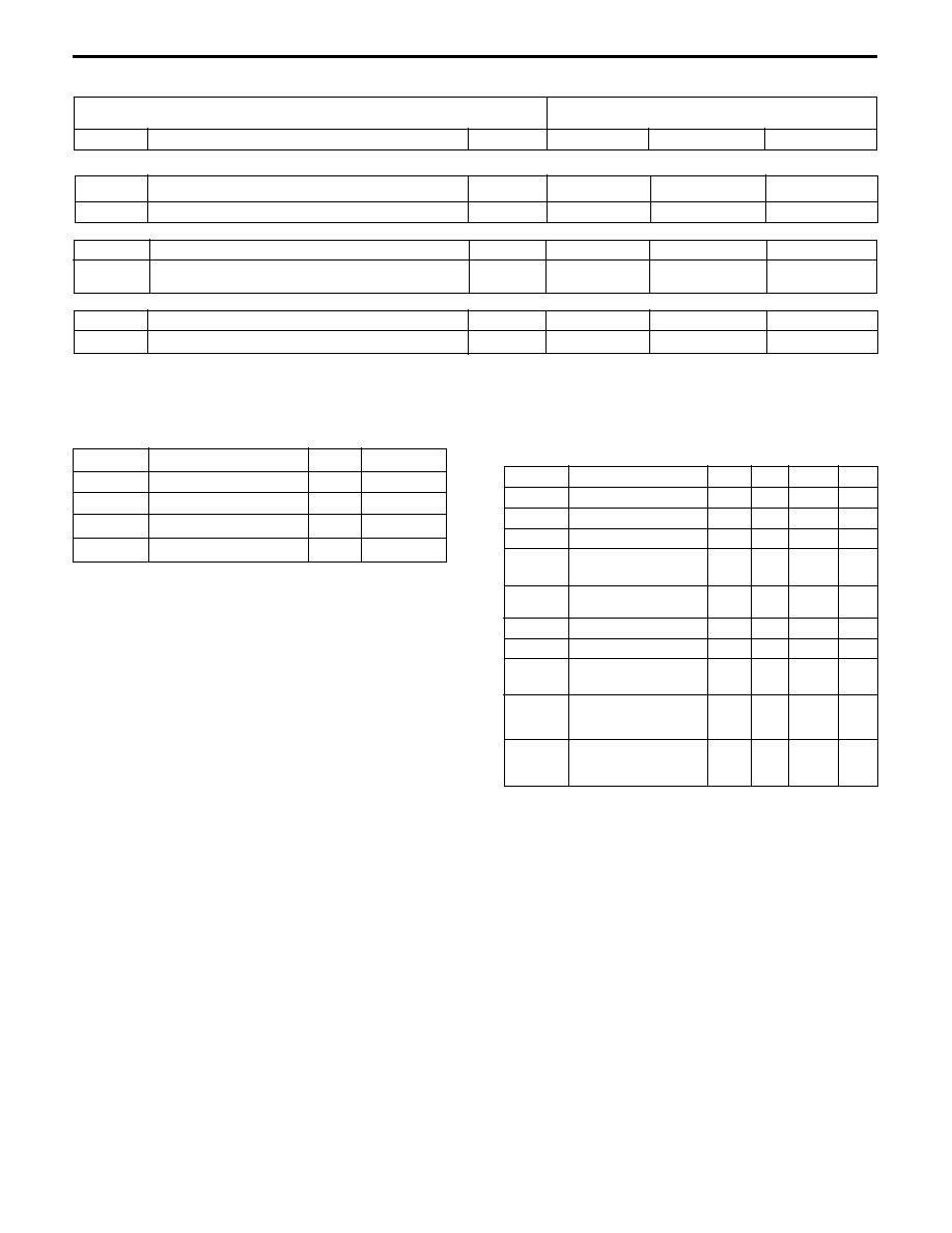
SYMBOLS
PARAMETERS AND CONDITIONS
UNITS
MIN
TYP
MAX
I
CC
Total Circuit Current, No Signals
mA
25
31
V
CC
Supply Voltage
V
2.7
3.0
3.3
LNA (f
RFin
= 1575.42 MHz, Z
L
= Z
S
= 50
)
)
)
)
)
Z
LNAin
RF Input Impedance of LNA
28 - j38
Z
LNAop
RF Output Impedance of LNA
85 - jx6
P
1dBLNA
1 dB Compression, Input matched
dBm
-22
PG
LNA
Power Gain LNA, Input matched, P
RFin
= -60 dBm
dB
14
15
NF
LNA
Noise Figure of LNA, Input matched
dB
2.8
3.2
Mixer (f
RFin
= 1575.42 MHz, f
1stLOin
= 1636.80 MHz, P
LO
= -10 dBm, f
1stIF
= 61.38 MHz, Z
L
= Z
S
= 50
)
Z
MIXin
RF Input Impedance of Mixer
31 -j103
P
1dBMIX
1 dB Compression (refer to input), Input matched
dBm
-25
PCG
MIX
Power Conversion Gain
dB
21
NF
MIX
Noise Figure of Mixer (SSB), Input matched
dB
9.5
10
A
LO-IF
LO Leakage to IF Pins, P
LO
= -10 dBm
dBm
-40
A
LO-RF
LO Leakage to RF Input Pins, P
LO
= -10 dBm
dBm
-48
Z
MIXout
RF Output Impedance of Mixer
+152 - j9
PLL
I
CPOH
PLL Charge Pump High Side Current @ V
CPout
= V
CC/
2
mA
1
I
CPOL
PLL Charge Pump Low Side Current @ V
CPout
= V
CC/
2
mA
-1
f
PD
Phase Comparison Frequency
MHz
8.184
IF Downconverter Block (f
1stIFin
= 61.38 MHz, f
2ndLOin
= 65.472 MHz, f
2ndIF
output = 4.092 MHz, Z
S
= 2k
, Z
L
= 2 k
)
NF
2ndMIX
Noise Figure of 2nd IF Mixer (SSB), (Z
S
= 50
)
dB
12
GV
2ndMIX
Voltage Gain of 2nd Mixer/Amplifier, P
1stIF
= -50 dBm
dB
47
V
GC
Gain Control Voltage (Voltage at maximum gain)
V
0.5
D
GC
Gain Control Range, P
1stIF
= -50 dBm
dB
20
(Voltage at maximum gain)
A
2ndLO1stIF
2nd LO Isolation to 1st IF Input Pins, V
AGC
= 0 V
dB
-70
A
2ndLO2ndIF
2nd LO Isolation to 2nd IF Output Pins, V
AGC
= 0 V
dB
-70
FEATURES
UPB1007K
NEC's 3 V DUAL
DOWNCONVERTER AND
PLL FREQUENCY SYNTHESIZER
DESCRIPTION
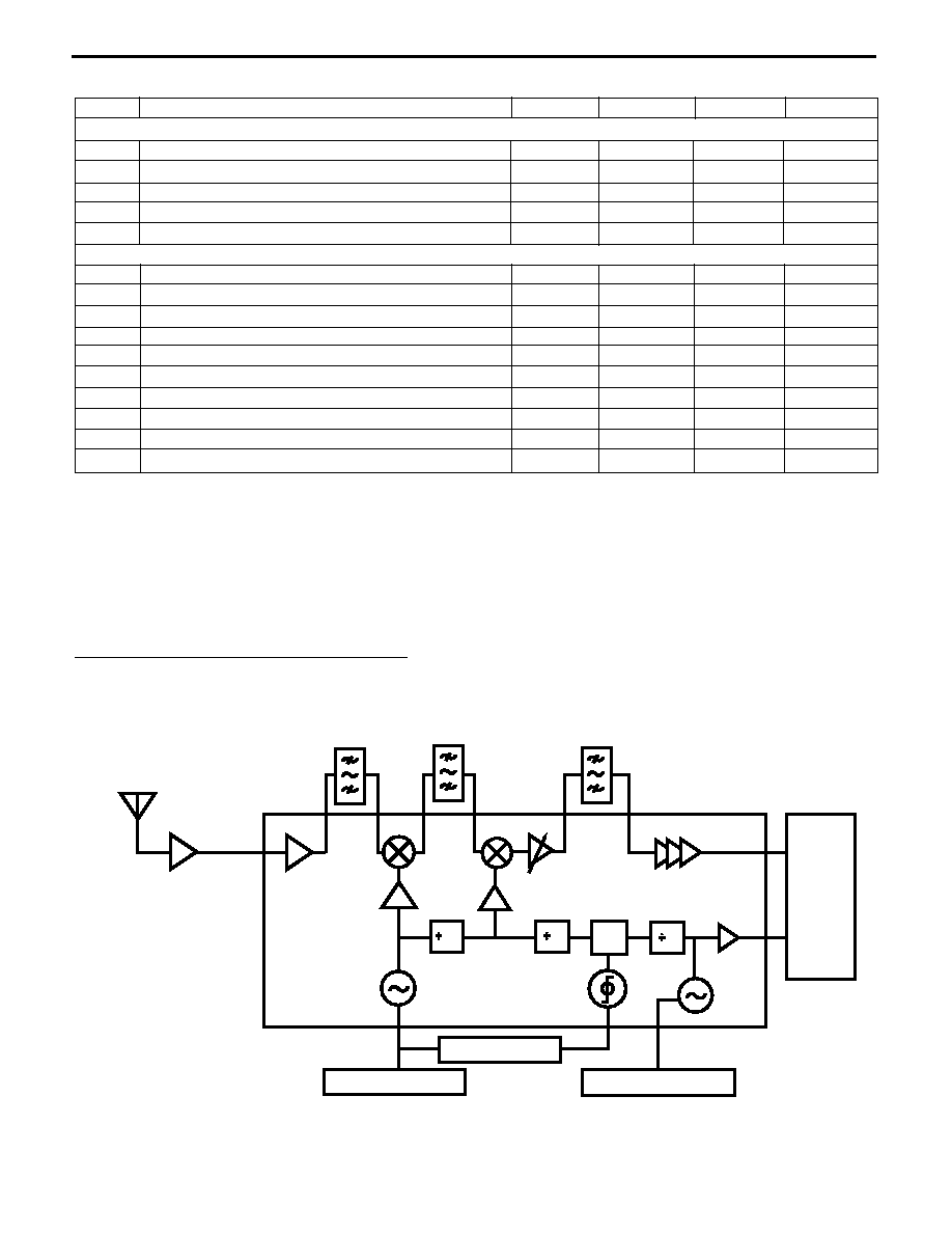
NEC's UPB1007K is a Silicon RFIC designed for low cost GPS
receivers. The IC combines an LNA, followed by a double-
conversion RF/IF downconverter block and a PLL frequency
synthesizer on one chip. The device operates on a 3V supply
voltage and is housed in a small 36 pin QFN (Quad Flat No-
lead) package, resulting in low power consumption and re-
duced board space. The device is manufactured using the
state of the art UHS0 25 GHz f
T
silicon bipolar process.
NEC's stringent quality assurance and test procedures en-
sure the highest reliability and performance.
ELECTRICAL CHARACTERISTICS
(T
A
= 25
∞
C, V
CC
= 3.0 V, unless otherwise specified)
APPLICATIONS
∑ LOW POWER HANDHELD GPS RECEIVER
∑ IN-VEHICLE NAVIGATION SYSTEMS
∑ PC/PDA+GPS INTEGRATION
∑ INTEGRATED RF BLOCK:
LNA, RF & IF Downconverter + PLL frequency
synthesizer
∑ STATE OF THE ART 25 GHz f
T
UHS0 BIPOLAR
PROCESS
∑ DOUBLE-CONVERSION: f
1stIF
= 61.380 MHz
f
2ndIF
= 4.092 MHz
∑ ADJUSTABLE GAIN: 20 dB range MIN
∑ FIXED DIVISION PRESCALER
∑ LOW POWER CONSUMPTION: 25 mA @ 3 V
∑ SMALL 36 PIN QFN PACKAGE
Flat lead style for better performance
∑ TAPE AND REEL PACKAGING AVAILABLE
California Eastern Laboratories
UPB1007K
ABSOLUTE MAXIMUM RATINGS
1,2
(T
A
= 25
∞
C)
Notes:
1. Operation in excess of any one of these parameters may result
in permanent damage.
2. More than two items must not be reached simultaneously.
3. T
A
= +85
∞
C, mounted on a 50 x 50 x 1.6 mm double-sided
copper clad epoxy glass PWB.
SYMBOLS
PARAMETERS
UNITS MIN
TYP
MAX
V
CC
Supply Voltage
V
2.7
3.0
3.3
T
OP
Operating Temperature
∞
C
-40
+25
+85
f
RFin
RF Input Frequency
MHz
1575.42
f
REFin
Reference Frequency
MHz
16.368
f
REFout
f
1st
LO
1st LO Oscillating
Frequency
MHz
1636.8
f
1stIFin
1st IF Input Frequency
MHz
61.38
f
2ndLOin
2nd LO Input Frequency MHz
65.472
f
2ndIFin
2nd IF Input/Output
f
2ndIFout
Frequency
MHz
4.092
VIH
Power Down Control
Voltage "High"
V
1.8
3
VIL
Power Down Control
Voltage "Low"
V
0.6
RECOMMENDED
OPERATING CONDITIONS
SYMBOLS
PARAMETERS
UNITS
RATINGS
V
CC
Supply Voltage
V
3.6
P
T
Total Power Dissipation
3
mW
433
T
OP
Operating Temperature
∞
C
-40 to +85
T
STG
Storage Temperature
∞
C
-55 to +150
PART NUMBER
UPB1007K
PACKAGE OUTLINE
QFN-36
SYMBOLS
PARAMETERS AND CONDITIONS
UNITS
MIN
TYP
MAX
2nd IF Amplifier Block (f
2ndIF
= 4.096 MHz, Z
S
= 2k
, Z
L
= 2 k
)
)
)
)
)
GV
LIM
Voltage Gain of Limiter Amplifier, P
IN
= -60 dBm
dB
48
f
BB
Roll-off Frequency
MHz
110
Reference Amplifier Block
V
REFin
Reference Input Minimum Level
mVpp
400
400
V
REFout
Reference Output Swing (open collector output),
C
L
= 2 pF//R
L
= 10 k
Vpp
1.1
1.2
1.3
Power Down Control Pins
VIH
Digital Control Input High
V
1.83
1.86
2.15
VIL
Digital Control Input Low
V
0.5
0.6
ELECTRICAL CHARACTERISTICS
(T
A
= 25
∞
C, V
CC
= 3 V, unless otherwise specified)
SYMBOL
PARAMETER AND CONDITIONS
UNITS
MIN
TYP
MAX
IC Performance Parameters
V
CC
Supply Voltage
V
2.7
3.0
3.3
I
CC
Total Circuit Current, V
CC
= 3.0 V, no signal
mA
25
31
I
CC_PL
Power Down Node Current
mA
0.15
I
CC_XO
Oscillator Supply Current, (Pin 15 = 0 V, Pin 16 = 3 V)
mA
2.7
I
CC_RX
Receiver Supply Current, (Pin 15 = 0 V, Pin 16 = 3 V)
mA
22.3
Functional Blocks Current Details
I
CC_LNA
Supply Current of LNA, RF off
mA
2.6
I
CC_MIX1
Supply Current of RF Mixer, RF off
mA
6.7
I
CC_MIX2
Supply Current of IF Mixer, RF off
mA
3.5
I
CC_IFAMP
Supply Current of IF Amplifier, RF off
mA
1.1
I
CC_XO
Crystal Oscillator Supply Current
mA
2.7
I
CC
9
PLL Supply Current
mA
6.3
I
CC_CF
Control Functions Supply Current
µ
A
2.1
V
IL
Power Down Pin Logic LOW Level
V
0.6
V
IH
Power Down Pin Logic HIGH Level
V
1.8
d
_
PON
Power-on Response Time
ms
3
CURRENT BUDGET
UPB1007K
APPLICATION EXAMPLE
1575.42 MHz
1575.42 MHz
1575.42 MHz
8
PD
BASEBAND
IC
25
2
LOOP FILTER
TUNING ELEMENT
REFERENCE FREQ.

Pin No.
Symbol
Function and Application
Internal Equivalent Circuit
1
LNAout
2
V
CC
(V
reg
)
3
GND (V
reg
)
4
RF MIX
in
5
GND (MIX)
6
1stLO-OSC1
7
1stLO-OSC2
8
V
CC
(1stLO-OSC)
9
V
CC
(Charge Pump)
10
PD-out
11
GND
(Charge Pump)
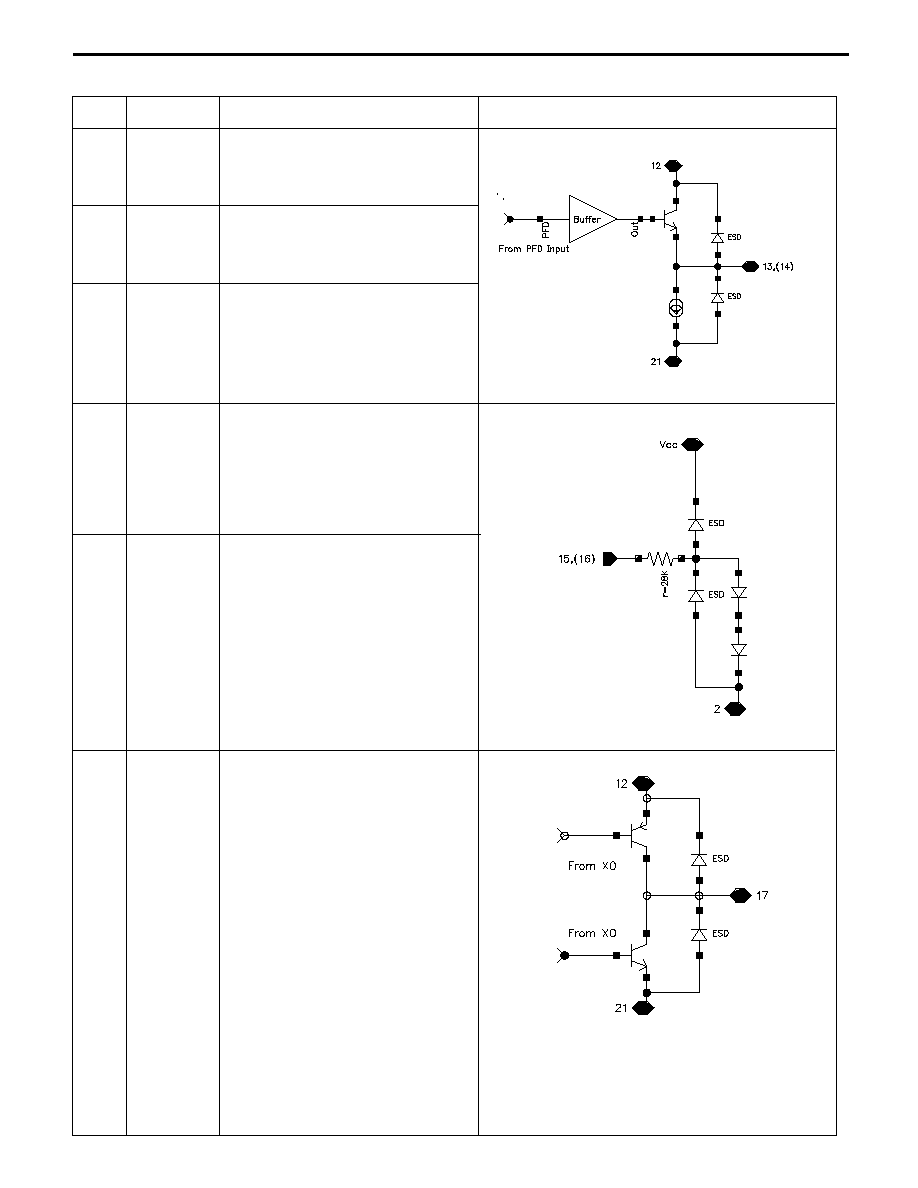
PIN FUNCTIONS
Output pin of LNA. Output biasing
and matching required as it is an open
collector output.
Supply voltage pin of regulator mixer
block.
Input pin of RF mixer. 1575.42 MHz
band pass filter can be inserted between
pin 1 and mixer input.
Ground pin of RF mixer cell.
This is a current mode charge pump
output for connection to a passive RC
loop filter for driving the external varactor
diode of 1stLO-OSC.
Supply voltage pin of the phase detector
charge pump.
Ground pin of regulator reference cell.
UPB1007K
Pins 6 & 7 are base pins of the differential
amplifier for 1st LO oscillator. These pins
should be equipped with LC and varactor
circuits to oscillate at 1636.8 MHz.
Supply voltage pin of differential amplifier
for 1st LO oscillator circuit (VCO).
Ground pin of phase detector charge
pump.
Pin No.
Symbol
Function and Application
Internal Equivalent Circuit
12
V
CC
(Divider Block)
13
LO_out
14
XO_out
15
PD1
16
PD2
17
REFout
PIN FUNCTIONS
UPB1007K
Supply voltage pin of prescaler, phase
detector, crystal oscillator, VCO buffer.
Monitor pin of frequency at phase
detector.
Power down control pin
Low = Whole chip off except XTAL osc.
High = Whole chip on except XTAL osc.
Reference block standby mode.
Low = Reference block disabled.
High = Reference block enabled.
Monitor pin of oscillator
˜
2 output at
phase detector.
Output pin of reference frequency. The
frequency from pin 17 can be taken out as
1Vp-p swing.
Pin No.
Symbol
Function and Application
Internal Equivalent Circuit
18
REF gnd
19
REF
in
20
V
CC
(Ref Block)
21
GND
(Ref Block)
22
2nd IF
out
23
V
CC
2ndIFAMP
24
2ndIF bypass
25
2ndIFin1
26
2ndIFin2
27
GND
(2ndIF AMP)
28
IF MIXout
29
V
CC
(IF MIX)
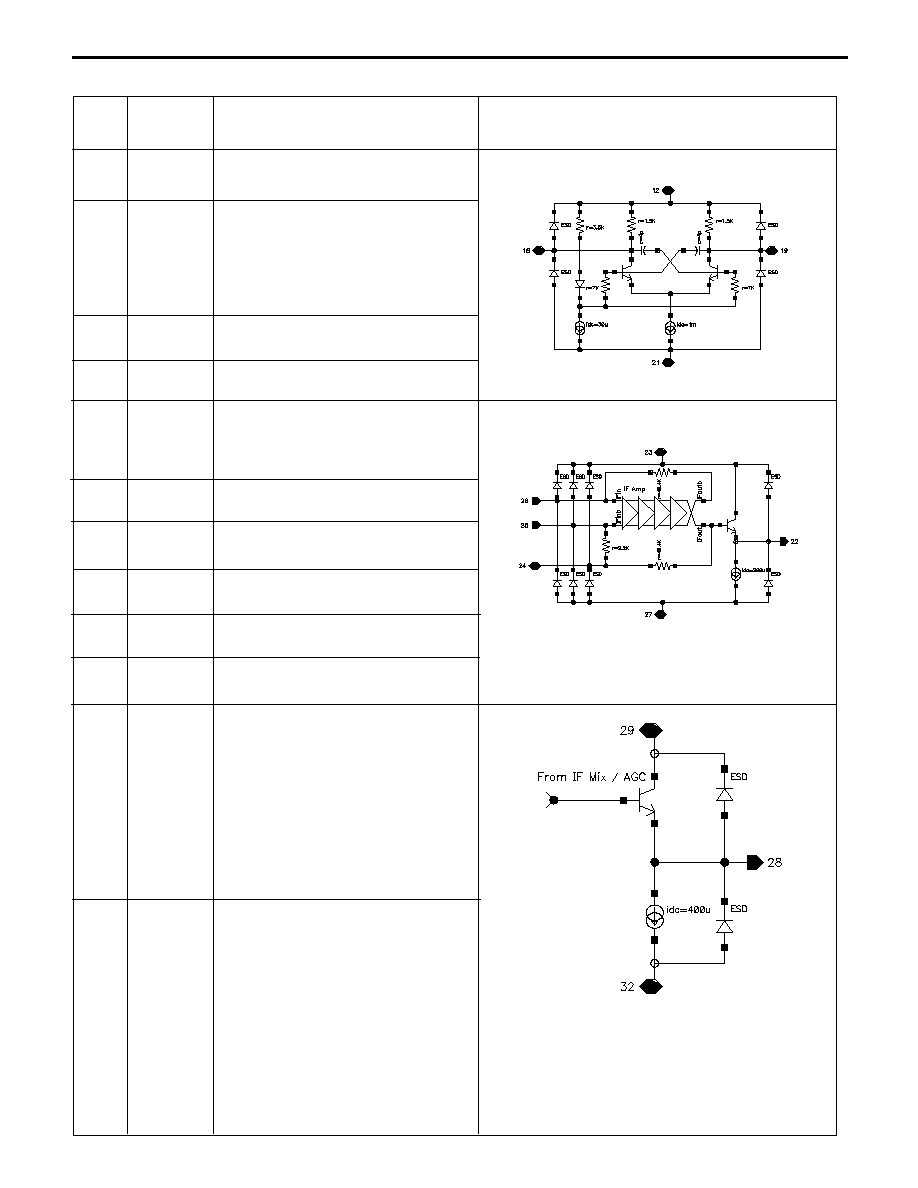
PIN FUNCTIONS
Output pin from IF mixer. IF mixer output
signal goes through gain control amplifier
before this emitter follower output port.
Bypass pin of 2nd IF amplifier input. This
pin should be grounded via a capacitor.
Pin 2 of 2nd IF amplifier input. This pin
should be grounded via a capacitor.
Supply voltage pin of IF mixer, gain control
amplifier.
Pin 1 of 2nd IF amplifier input . 2nd IF filter
can be inserted between 25 & 28.
Ground pin of 2nd IF amplifier.
Differential oscillator input.
This pin should be grounded via a capacitor.
Input pin of the reference frequency
buffer. This pin should be equipped with
an external 16.368 MHz oscillator (e.g.
TCXO).
Supply voltage pin of output charge pump
of the oscillator.
Ground pin of the oscillator, prescaler,
phase detector and VCO.
Output pin of 2nd IF amplifier. This pin
output 4.092 MHz clipped sinewave. This
pin should be equipped with external
inverter to adjust level to next stage on
user's system.
Supply voltage pin of 2ndIF amplifier
UPB1007K

Pin No.
Symbol
Function and Application
Internal Equivalent Circuit
30
V
GC
(IF MIX)
31
IF-MIXin
32
GND (IF-MIX)
33
RF-MIXout
34
V
CC
(RF-MIX)
35
LNA
in
36
GND (LNA)
PIN FUNCTIONS
Gain control voltage pin of IF mixer output
amplifier. This voltage performs forward
control, i.e., (V
GC
up
Gain down).
Input pin of IF mixer and IF VAGC.
Ground pin of IF mixer and IF VAGC.
Output pin of RF mixer . 1st IF filter must
be inserted between pins 31 and 33.
Supply voltage pin of RF mixer block. This
pin must be decoupled with capacitor (e.g.
1000 pF).
Input pin of low noise amplifier. Optimal
See Pins 1-3
input matching required for low noise
performance.
Ground pin of LNA.
UPB1007K

UPB1007K
A Business Partner of NEC Compound Semiconductor Devices, Ltd.
02/28/2003
Life Support Applications
These NEC products are not intended for use in life support devices, appliances, or systems where the malfunction of these products can reasonably
be expected to result in personal injury. The customers of CEL using or selling these products for use in such applications do so at their own risk and
agree to fully indemnify CEL for all damages resulting from such improper use or sale.
INTERNAL BLOCK DIAGRAM
/25
/2
/8
PD
Vreg
27
26
25
23
24
22
21
20
19
1
2
3
5
4
6
7
8
9
35
33
30
28
34
31
29
32
36
11
13
16
18
12
15
17
14
10
GND
(2ndIF-Amp)
2ndIFin1
2ndIFin2
2ndIFbypass
V
CC
(2ndIF-Amp)
2ndIFout
GND
(Div & Ref Block)
V
CC
(Ref Block)
REFin
PDout
GND
(charge pump)
V
CC
(divider block)
Pres_LOout
XO_out
REF gnd
Power Down 1
(whole chip)
Power Down 2
(Ref Block)
REFout
LNAout
V
CC
(Vreg)
V
CC
(RF-MIX)
GND
(IF-MIX)
V
GC
(IF-MIX)
V
CC
(IF-MIX)
IF-MIXin
GND
(Vreg)
RF-MIXin
GND
(MIX/LO)
1stLO-OSC1
1stLO-OSC2
V
CC
(1stLO-OSC1)
V
CC
(charge pump)
GND
(LNA)
LNAin
RF-MIXout
IF-MIXout
Note:
1. The solder pads on each corner should be grounded.
OUTLINE DIMENSIONS
(Units in mm)
Package Outline QFN-36
1
Pin 1
Pin 36
4 -CO.5
6.2±0.2
6.0±0.2
6.0±0.2
6.2±0.2
6.2±0.2
6.0±0.2
6.2±0.2
6.0±0.2
1.0 MAX
0.55±0.2
0.22±0.05
0.5±0.025
0.14
-0.05
+0.10
Part Number
Package
UPB1007K
36 Pin plastic QFN
ORDERING INFORMATION
3.8
0.5
6.4
6.0
ACTUAL SIZE
(Units in mm)
Package Outline QFN-36