 | ÐлекÑÑоннÑй компоненÑ: CMD8649 | СкаÑаÑÑ:  PDF PDF  ZIP ZIP |
Äîêóìåíòàöèÿ è îïèñàíèÿ www.docs.chipfind.ru
CMD8649
(Preliminary)
Lens Motor Driver for Digital Still Camera
* All specs and applications shown above subject to change without prior notice.
1F-5 NO.66 SEC.2 NAN-KAN RD ., LUCHU , TAOYUAN, TAIWAN
Email: server@ceramate.com.tw
Tel:886-3-3214525 Http: www.ceramate.com.tw
Fax:886-3-3521052
Page 1 of 8
Rev 0.1 Mar. 3,2004
1. Case Outline: SQFP48(7
×
7) Plastic Package
VB max
VB power supply
10.5
Maximum supply voltage
VCCmax
VCC power supply
10.5
V
Max input application voltage
VIN max
10.5
V
Max output application voltage
VOUT max
10.5
V
Maximum output current
Io max
per CH
600
mA
Allowable power dissipation
Pd max
Substrate mounting
1.0
W
Operating temperature
Topr
-20 to +80
°C
Storage temperature
Tstg
-55 to +150
°C
(*1) Mounting substrate: 76.1mm
×
114.3mm
×
1.6mmt, glass epoxy
4. Allowable Operating Ranges at Ta=25°C
Parameter
Symbol
Conditions
Ratings
Unit
VB1,2,3
(*2)
1.9 to 10
Supply voltage range
VCC
1.9 to 10
V
Input pin H voltage
VINH
1.8 to 10
V
Input pin L voltage
VINL
-0.3 to 0.4
V
Constant voltage setting input range VOC
VC1,VC2
0.1 to VB
V
Constant current setting input range VOI
IAE,ISH
0.1 to 1.0
V
(*2) NO hierarchical relationship between VB1, 2, VDD, VCC and VIN.
Example 1: VB1=VB2=VDD=2.4V(Battery power supply), VCC=4V (step-up power supply)
VIN (CPU power supply)=5V
Example 2: VB1=VB2=2.4V, VIN=3.3V, VDD=VCC=5V
0
0.2
0.4
0.6
0.8
1
1.2
-20
0
20
40
60
80
100
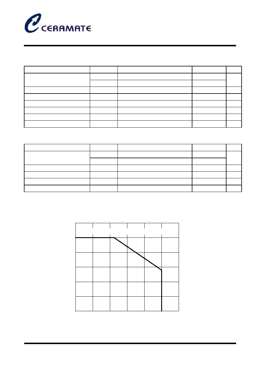
Ambient Temperature, Ta -
°
C
Mounted on a board(76.1mm
×
114.3mm
×
1.6mmt, glass epoxy)
Allowable power dissipation, Pdmax - W
Pd max - Ta
0.56
2. Function and Application: DSC driver
Parameter
Symbol
Conditions
Ratings
Unit
3. Absolute Maximum Ratings at Ta=25°C
(B8-6247)
CMD8649
(Preliminary)
Lens Motor Driver for Digital Still Camera
* All specs and applications shown above subject to change without prior notice.
1F-5 NO.66 SEC.2 NAN-KAN RD ., LUCHU , TAOYUAN, TAIWAN
Email: server@ceramate.com.tw
Tel:886-3-3214525 Http: www.ceramate.com.tw
Fax:886-3-3521052
Page 2 of 8
Rev 0.1 Mar. 3,2004
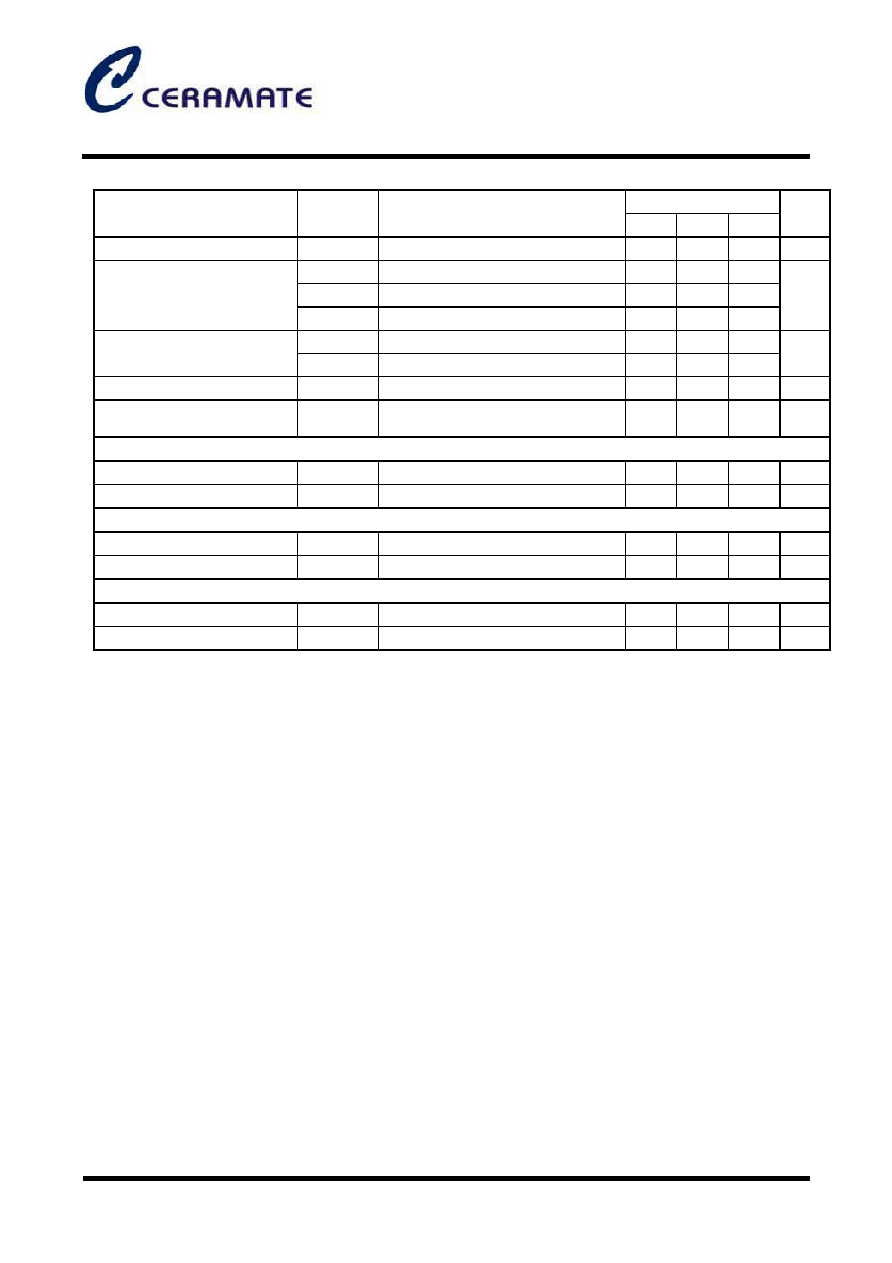
5. Electrical Characteristics (VB=VCC=2.4V, Rf=1
)/Ta=25°C
Ratings
Parameter
Symbol
Conditions
Min
Typ
Max
Unit
Standby current dissipation
ICC0
VB1=VB2=VCC=VDD=8.0V (*3)
0.1
5.0
mA
ICC1
IN1orIN2 or IN3orIN4=H (*3)
6
9
ICC2
IN5orIN6 or IN7orIN8=H (*3)
14
19
Operating current dissipation
ICC3
IN9orIN10 or IN11orIN12
H (*3)
18
25
mA
Vref1
Iref=-1mA
INHD=L
0.95
1.0
1.05
Reference voltage
Vref2
Iref=-1mA
INHD=H
0.64
0.67
0.70
V
Control pin input current
I IN
VIN=5.0V
60
90
mA
Overheat protection operation
temperature
THD
Design guarantee (*4)
160
180
200
°C
AF/STP constant-voltage stepping motor driver(OUT1, 2, 3, 4)
Output constant voltage 1
VO1
VC1=0.30V
1.46
1.53
1.60
V
Output saturation voltage 1
VSAT1
Io=0.2A(Upper side + Lower side)
0.27
0.37
0.50
V
Constant-voltage driver for ZOOM (OUT5, 6, 7, 8)
Output constant current 2
VO2
VC2=0.30V
1.46
1.53
1.60
V
Output saturation voltage 2
VSAT2
Io=0.2A(Upper side + Lower side)
0.27
0.37
0.50
V
Constant-current driver for SH/AE (OUT9, 10, 11, 12)
Output constant current
IO
Rf=1
,ISH=0.3V
271
285
302
mA
Output saturation voltage 3
VSAT3
Io=0.3A(Upper side + Lower side)
0.33
0.44
0.60
V
(*3) Determined by the sum of the current drain of VB1, VB2, VDD, and VCC lines.
(*4) For characteristics within the temperature guarantee range, carry out the shipment inspection at Ta =25°C,
instead of at all temperatures, for design guarantee.
CMD8649
(Preliminary)
Lens Motor Driver for Digital Still Camera
* All specs and applications shown above subject to change without prior notice.
1F-5 NO.66 SEC.2 NAN-KAN RD ., LUCHU , TAOYUAN, TAIWAN
Email: server@ceramate.com.tw
Tel:886-3-3214525 Http: www.ceramate.com.tw
Fax:886-3-3521052
Page 3 of 8
Rev 0.1 Mar. 3,2004
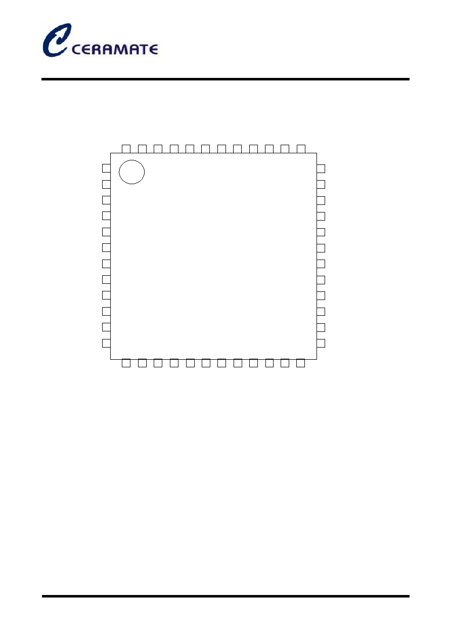
6. Pin Assignment/SQFP48
37
38
41
40
42
46
48
47
45
44
43
39
5
4
3
2
1
7
6
9
8
1
1
1
20
13
14
15
16
17
18
19
21
22
23
24
35
34
36
25
27
26
28
30
29
31
33
32
INHD
IN12
OUT7
(NC
)
IN11
IN10
IN9
IN8
IN7
IN6
IN5
IN4
IN3
IN2
IN1
(NC
)
IAE
ISH
VC2
VC1
VREF
VCC
VB2
(NC
)
PGN
D
OUT8
OUT6
OUT5
RFG2
OUT11
OUT10
OUT12
RFG1
OUT9
OUT4
OUT3
OUT2
SG
ND
(NC
)
VDD
F
C
2
F
C
1
(N
C
)
VCC
VB1
(NC
)
PGN
D
OUT1
Note: Connect PGND at two points.
VDD: Input, reference voltage, logic power supply
VCC: Power supply for constant-current control and outputs (OUT9, 10, 11, and 12)
VB1: Power supply for constant-voltage control and outputs (OUT1, 2, 3, and 4)
VB2: Power supply for constant-voltage control and outputs (OUT5, 6, 7, and 8)
CM
D
86
4
9
CMD8649
(Preliminary)
Lens Motor Driver for Digital Still Camera
* All specs and applications shown above subject to change without prior notice.
1F-5 NO.66 SEC.2 NAN-KAN RD ., LUCHU , TAOYUAN, TAIWAN
Email: server@ceramate.com.tw
Tel:886-3-3214525 Http: www.ceramate.com.tw
Fax:886-3-3521052
Page 4 of 8
Rev 0.1 Mar. 3,2004
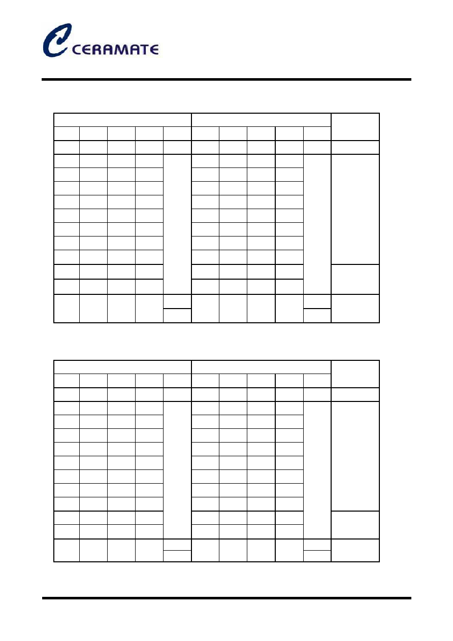
7. Truth Table
(1) Stepping motor constant-voltage control for AF
Input
Output
IN1
IN2
IN3
IN4
INHD
OUT1
OUT2
OUT3
OUT4
Vref
Mode
L
L
L
L
L
-
-
-
-
-
Standby
H
L
L
L
H
L
-
-
H
L
H
L
H
L
H
L
L
L
H
L
-
-
H
L
L
H
H
L
L
H
H
L
L
H
L
L
L
H
-
-
L
H
L
H
L
H
L
H
L
L
L
H
-
-
L
H
H
L
L
H
H
L
L
H
1 - 2 phase
excitation
H
H
*
*
-
-
*
*
H
H
L
-
-
1.0V
Output OFF
L
1.0V
*
*
*
*
H
0.67V
-: Output OFF
For output "H", VC1
×
5.1 is output.
(2) Stepping motor constant-voltage control for ZOOM or DC motor drive
Input
Output
IN5
IN6
IN7
IN8
INHD
OUT5
OUT6
OUT7
OUT8
Vref
Mode
L
L
L
L
L
-
-
-
-
-
Standby
H
L
L
L
H
L
-
-
H
L
H
L
H
L
H
L
L
L
H
L
-
-
H
L
L
H
H
L
L
H
H
L
L
H
L
L
L
H
-
-
L
H
L
H
L
H
L
H
L
L
L
H
-
-
L
H
H
L
L
H
H
L
L
H
1 - 2 phase
excitation
H
H
*
*
H
H
*
*
H
H
L
H
H
1.0V
Brake
L
1.0V
*
*
*
*
H
0.67V
-: Output OFF *: Don't care
For output "H", VC2
×
5.1 is output.
CMD8649
(Preliminary)
Lens Motor Driver for Digital Still Camera
* All specs and applications shown above subject to change without prior notice.
1F-5 NO.66 SEC.2 NAN-KAN RD ., LUCHU , TAOYUAN, TAIWAN
Email: server@ceramate.com.tw
Tel:886-3-3214525 Http: www.ceramate.com.tw
Fax:886-3-3521052
Page 5 of 8
Rev 0.1 Mar. 3,2004
(3) VCM constant-current control for SH/AE or stepping motor drive
Input
Output
IN9
IN10
IN11
IN12
INHD
OUT9
OUT10
OUT11
OUT12
Vref
ISH
Mode
L
L
L
L
-
-
-
-
-
-
Standby
H
L
*
*
H
L
L
H
*
*
L
H
*
*
H
L
H
L
*
*
L
H
L
L
H
1.0V
SH
&
AE
H
L
*
*
H
L
L
H
*
*
L
H
*
*
H
L
H
L
*
*
L
H
L
H
Set
voltage
condition
Hole
L
L
L
L
H
-
-
-
-
0.67V
Discharge
Standby
-: Output OFF *: Don't care
·
OUT9 and 10 are for SH and have the stable start characteristics because of rapid charge and discharge circuits.
·
OUT10 and 11 are for AE.
·
At standby, the ISH pin voltage is put into the discharge condition by an internal transistor and set to 0 V.
·
ISH pin is also in the discharge condition (for rise compensation) when IN1 - 8 are entered.
·
The Vref voltage is 1.0 V with 1NHD = "L" and 0.67 V with 1NHD = "H."
8. Considerations for Design
(1) Constant-current setting (ISH, IAE, RFG1, 2, OUT9 to 12)
The constant current between OUT9 and OUT10 is set from the ISH input voltage and RFG1 connection resistance.
Control is made so that the voltage generated at a current detection resistor connected between RFG1 and GND is equal to the
ISH input voltage as shown in the block diagram. The output current is calculated as follows:
(Output current between OUT9 and OUT10) = (ISH input voltage)