 | –≠–ª–µ–∫—Ç—Ä–æ–Ω–Ω—ã–π –∫–æ–º–ø–æ–Ω–µ–Ω—Ç: CO8301 | –°–∫–∞—á–∞—Ç—å:  PDF PDF  ZIP ZIP |
CO8301
(Preliminary)
Stereo Headphone Amplifier
* All specs and applications shown above subject to change without prior notice.
1F-5 NO.66 SEC.2 NAN-KAN RD ., LUCHU , TAOYUAN, TAIWAN
Email: server@ceramate.com.tw
Tel:886-3-3214525
Http: www.ceramate.com.tw
Fax:886-3-3521052
Page 1 of 9
Rev 0.1 Mar. 25, 2003
Description
The CO8301 is a monolithic integrated circuit and
suitable dual amplifier for low power.
Feature
l
Low quiescent current
l
High power supply ripple rejection
l
Low voltage operation
l
A few of external part required
l
Built in power save switch
l
Built in mute switch
Typical Applications
l
Portable compact disk player (DISCMAN)
l
Portable mini disk player (MD)
l
Disc-Man
l
MP3 Player
l
CD-Rom
l
Other portable compact Disk Media Fan Motor Driver
10-SSOP-225
1
CO8301
(Preliminary)
Stereo Headphone Amplifier
* All specs and applications shown above subject to change without prior notice.
1F-5 NO.66 SEC.2 NAN-KAN RD ., LUCHU , TAOYUAN, TAIWAN
Email: server@ceramate.com.tw
Tel:886-3-3214525
Http: www.ceramate.com.tw
Fax:886-3-3521052
Page 2 of 9
Rev 0.1 Mar. 25, 2003
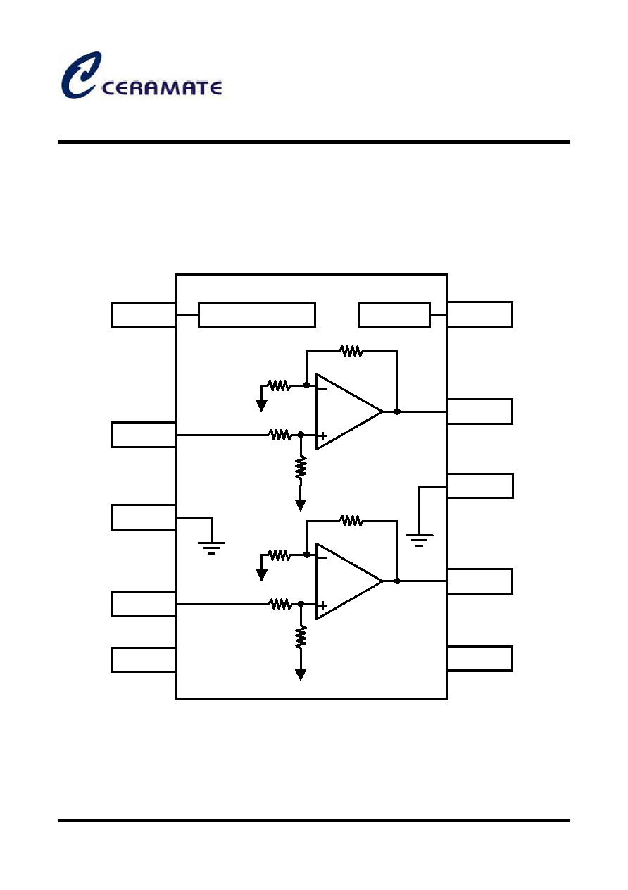
Block Diagram
1
2
4
3
5
6
7
8
9
10
POWER SAVE SWITCH CTL
MUTE CTL
REF
REF
REF
REF
PS
IN
A
GND
IN
B
REF
V
CC
OUT
B
GND
OUT
A
MUTE
CO8301
(Preliminary)
Stereo Headphone Amplifier
* All specs and applications shown above subject to change without prior notice.
1F-5 NO.66 SEC.2 NAN-KAN RD ., LUCHU , TAOYUAN, TAIWAN
Email: server@ceramate.com.tw
Tel:886-3-3214525
Http: www.ceramate.com.tw
Fax:886-3-3521052
Page 3 of 9
Rev 0.1 Mar. 25, 2003
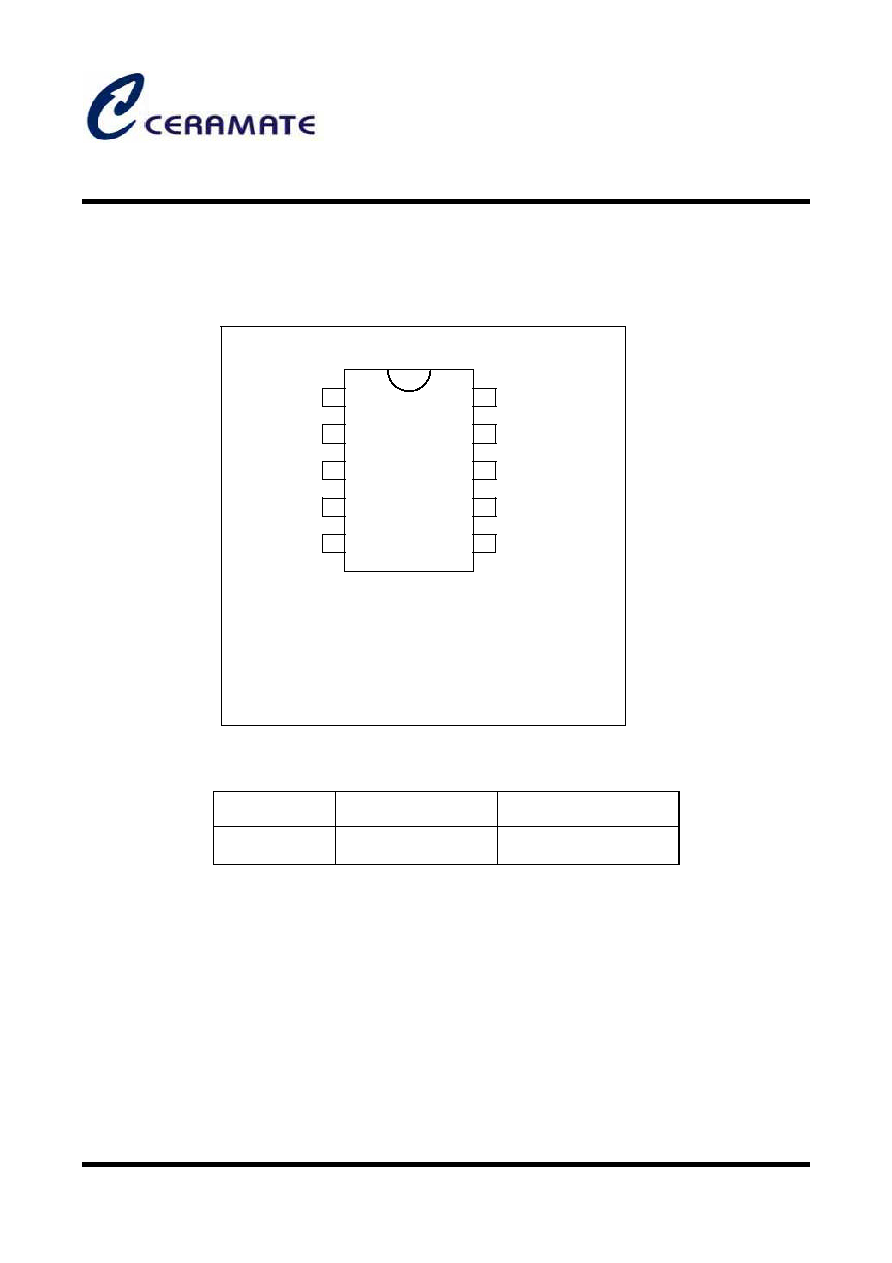
Pin Configuration
Ordering Information
Device
Package
Operating Temp.
CO8301 10-SSOP-225 -20
~ +75
.
1-Power save switch
2-Signal input A
3-Signal ground
4-signal input B
5-Reference voltage
6-Supply voltage
7-Signal output B
8-Power ground
9-Signal output A
10-Mute on switch
1
2
3
4
5
6
7
8
9
10
CO8301
(Preliminary)
Stereo Headphone Amplifier
* All specs and applications shown above subject to change without prior notice.
1F-5 NO.66 SEC.2 NAN-KAN RD ., LUCHU , TAOYUAN, TAIWAN
Email: server@ceramate.com.tw
Tel:886-3-3214525
Http: www.ceramate.com.tw
Fax:886-3-3521052
Page 4 of 9
Rev 0.1 Mar. 25, 2003
Absolute Maximum Rating (Ta = 25
)
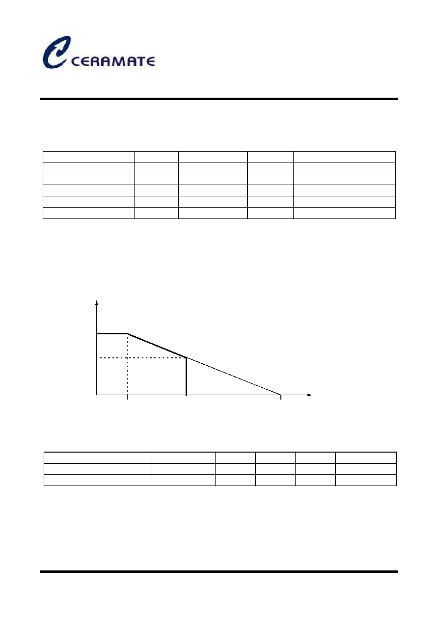
Power Dissipation Curve
Recommended Operating Conditions (Ta = 25
)
Parameter
Symbol
Value
Unit
Remark
Maximum Supply Voltage
V
CC
4.5
V
Maximum Supply Voltage
Power Dissipation
P
D
300
mW
Power Dissipation
Operating Temperature
T
OPR
-20 ~ +75
∞
C
Operating Temperature
Storage Temperature
T
STG
-55 ~ +125
∞
C
Storage Temperature
Thermal Resistance
T
ja
150
∞
C/W
-
Power dissipation (mW)
300
150
25
75
125
Ambient temperature, Ta (
∞
C)
Parameter
Symbol
Min.
Typ.
Max.
Unit
Operating Supply Voltage
V
CC
1.8
3.0
4.0
V
Recommended Load
R
L
16
-
32
CO8301
(Preliminary)
Stereo Headphone Amplifier
* All specs and applications shown above subject to change without prior notice.
1F-5 NO.66 SEC.2 NAN-KAN RD ., LUCHU , TAOYUAN, TAIWAN
Email: server@ceramate.com.tw
Tel:886-3-3214525
Http: www.ceramate.com.tw
Fax:886-3-3521052
Page 5 of 9
Rev 0.1 Mar. 25, 2003
Electrical Characteristics
(RL =16
, Rg =600
, Ta = 25
)
Parameter
Symbol
Conditions
Min.
Typ.
Max.
Unit
Quiescent Current 1
I
CC1
V
CC
= 2.4V
-
5.5
10.0
mA
Quiescent Current 2
I
CC2
V
CC
= 4.5V, Mute = GND
-
1.0
2.0
mA
Quiescent Current 3
I
CC3
V
CC
= 4.5V, PS = GND
-
-
1.0
µ
A
Close Loop Voltage Gain 1
G
VC1
V
CC
= 2.4V, f = 1kHz,
V
O
= -10dBm
30
32
34
dB
Close Loop Voltage Gain 2
G
VC1
V
CC
= 1.8V, f = 1kHz,
V
O
= -20dBm
29
32
34
dB
Channel Balance 1
G
V1
V
CC
= 2.4V, f = 1kHz,
V
O
= -10dBm
-
-
1.0
dB
Channel Balance 2
G
V2
V
CC
= 1.8V, f = 1kHz,
V
O
= -20dBm
-
-
1.0
dB
Total Harmonic Distortion
THD
V
CC
= 2.0V, f = 1kHz,
P
O
= 1mW
-
0.5
1.5
%
Ripple Rejection Ratio
RR
V
CC
= 1.8V, f = 100Hz,
Rg = 1k
, V
R
= -20dBm,
BPF = 100Hz
43
60
-
dB
Crosstalk
CT
V
CC
= 2.4V, f = 100Hz,
Rg = 1k
, V
O
= -10dB
43
50
-
dB
Output Noise Voltage
V
NOISE
V
CC
= 4.5V, Rg = 1k
,
BPF = 20Hz ~ 20kHz
-
60
100
µ
Vrms
Output Power
P
OUT
V
CC
= 3.0V, f = 1kHz,
THD = 10%
20
40
-
mW
PS Attenuation Ratio
ATT
PS
V
CC
= 1.8V, f = 100Hz,
PS = GND, V
IN
= -10dB
-
-
-80
dB
MUTE Attenuation Ratio
ATT
MU
V
CC
= 1.8V, f = 100Hz,
MUTE = GND, V
IN
= -10dB
-
-
-80
dB
PS ON Input Current
I
PSON
V
CC
= 1.5V, V
REF
0.85V
-
0.2
1.0
µ
A
MUTE OFF Input Current
I
MOFF
V
CC
= 1.5V, V
REF
0.85V
-
0.2
1.0
µ
A
PS ON High Level
V
HPS
V
CC
= 1.5V, V
REF
0.85V
0.5
0.65
-
V
MUTE OFF High Level
V
HMU
V
CC
= 1.5V, V
REF
0.85V
0.5
0.65
-
V