 | –≠–ª–µ–∫—Ç—Ä–æ–Ω–Ω—ã–π –∫–æ–º–ø–æ–Ω–µ–Ω—Ç: CS290N14 | –°–∫–∞—á–∞—Ç—å:  PDF PDF  ZIP ZIP |
Features
V
CC
Start
D
IN+
IN
-
25/75
AC
MB
Gnd
BI
CS
CVS
OUT
CS290
V
BAT
0.1
µ
F
330
27k
1k
55
18V
Ignition
Coil
5k
5k
V
IN+
V
IN
-
C
RUN
0.1
µ
F
C
ADAPTIVE
0.1
µ
F
3.2M
(optional)
15.3k
C
STALL
0.1
µ
F
200
56
200
4k
16k
0.05
Adjust for 6.5A (max)
Coil Current
s
40mA Driver
s
Stall Timing
s
Output Current Control
s
Output Clamp
s
Overvoltage Shutdown
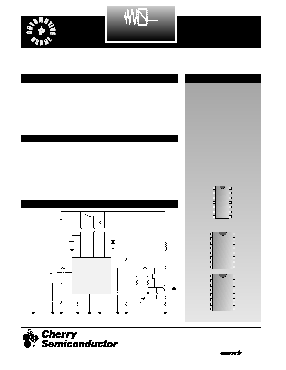
Package Options
CS290/291
Ignition Controller
CS290/291
Description
The CS290/291 are integrated cir-
cuits to be used in the automotive
ignition system. The application
diagram shown below highlights
the CS290. The CS291 is identical
with the differential input replaced
by a single-ended input. The part is
capable of withstanding 90V load
dump transients in the circuit
shown below. The part is also
reverse battery protected.
Application Diagram
Absolute Maximum Ratings
Power supply voltage, V
BAT
. . . . . . . . . . . . . . . . . . . . . . . . . . . . . . .-0.3V to 22V
Peak Transient Voltage (Load Dump 76V @ 14V V
BAT
) . . . . . . . . . . . . . . . .90V
Storage Temperature . . . . . . . . . . . . . . . . . . . . . . . . . . . . . . . . . . .-55∞C to 165∞C
Operating Junction Temperature, T
J
. . . . . . . . . . . . . . . . . . . . . . . . . . . . . .150∞C
Lead Temperature Soldering
Wave Solder (through hole styles only) . . . . . . .10 sec. max, 260∞C peak
Reflow (SMD styles only) . . . . . . .60 sec. max above 183∞C, 230∞C peak
1
Gnd
MB
AC
25/75
V
IN+
V
IN
-
Start
V
CC
D
CVS
OUT
NC
CS
BI
14 Lead PDIP
1
16 Lead SO Wide
A Company
Æ
Rev. 3/8/99
1
Gnd
MB
AC
25/75
V
IN+
V
IN
-
Start
V
CC
D
CVS
OUT
NC
CS
BI
NC
NC
1
Gnd
MB
AC
25/75
V
IN
-
Start
V
CC
D
CVS
OUT
TEST
CS
BI
NC
NC
NC
Consult Factory for Flip Chip
CS290
CS291
Cherry Semiconductor Corporation
2000 South County Trail, East Greenwich, RI 02818
Tel: (401)885-3600 Fax: (401)885-5786
Email: info@cherry-semi.com
Web Site: www.cherry-semi.com

s
Input
Positive Threshold
66
%V
BAT
Negative Threshold
V
BAT
=16V
29
%V
BAT
V
BAT
= 6V
29
Hysteresis
9
%V
BAT
Input Impedance
Input = 100µA
70
325
k
V
CC
Negative Edge Filter
V
BAT
= 16V
18
1100
µs
V
BAT
= 6V
4
1100
s
Output Stage
Negative Edge Delay
V
BAT
= 6V
1.1
3.1
ms
(Start Mode)
Positive Edge Delay
V
BAT
= 5V
1.06
1.80
ms
(Start Mode)
Delay Time
V
BAT
= 14V
0
16
µs
(Start High to Output Low)
Output Current
V
BAT
= 6V
40
65
mA
Output SOA
V
BAT
= 22V
40
65
mA
Output Leakage
V
BAT
= 18V
0
100
uA
Output Clamp Voltage
Output = 10mA
13.7
17
V
Output Clamp Impedance
Output = 10mA
10
80
(Refers to Collector Sense Voltage pin)
High Frequency On Time
V
BAT
= 14V
70
80
%
s
General
I
CC
V
BAT
= 6V
1.4
4.6
mA
V
BAT
= 16V
5
19
AC Gain
V
BAT
= 14V
0.8
1.2
V/V
Adaptive Cap Gain
V
CS
Regulation
V
BAT
= 6V
140
210
mV
High Voltage Shutdown
24.3
31
V
s
Stall
V
STALL
Soft Shutdown Voltage
V
CS
= 6V
0
11
mV
Soft Shutdown Frequency
V
BAT
= 14V
1.0
2.6
Hz
Soft Shutdown Time
V
BAT
= 6V
13.1
27
ms
Stall to Spark Output Delay
V
BAT
= 14V
4.5
8.9
ms
Battery Interrupt Time
V
BAT
= 14V
25
750
ms
Battery Interrupt Recovery Time
(200 Hz)
0
800
ms
s
Dwell
Dwell @ 10Hz
V
BAT
= 5V
46
54
%
(Start Mode)
Start to Output Disable Time
V
BAT
= 14V
65
135
ms
Excess Dwell @ 20Hz
V
BAT
= 14V
14
20.8
%
(Run Mode)
PARAMETER
TEST CONDITIONS
MIN
TYP
MAX
UNIT
2
Electrical Characteristics: 6V < V
B
< 16V, -30∞C < T
A
< 125∞C
CS290/291

3
CS290/291
Package Pin Description
PACKAGE PIN #
PIN SYMBOL
FUNCTION
16 lead SO wide
14 lead PDIP
CS290
CS291
1
6
6
Gnd
Signal Ground.
2
2
3
MB
Master Bias. Sets up operating currents on the IC with exter-
nal resistor.
3
3
4
AC
Adaptive Capacitor. Follows the 25/75 capacitor. Voltage
trip points control the Output for setting dwell.
4
4
5
25/75
Run Capacitor. Provides 25%/75% charge and discharge
current to an external capacitor for setting dwell.
5
5
NC
V
IN+
Input pin +.
6
7
7
V
IN-
Input pin -.
7
8
8
Start
Input pin to put device in the "start mode".
8
9
9
V
CC
Supply input voltage.
9
10
10
D
Supply current to output pin.
10
11
11
CVS
Collector Voltage Sense. Input for flyback detect.
11
12
12
OUT
Output. Driver for external darlington.
12
1,13,16
1,2,16
NC
No connection.
13
14
14
CS
Current Sense. Feedback for max coil current.
14
15
15
BI
Battery Int. Input for "stall mode" of operation
NC
NC
13
Test
Factory test pin. Pin should be grounded in customer
application.
PARAMETER
TEST CONDITIONS
MIN
TYP
MAX
UNIT
Electrical Characteristics: 6V < V
B
< 16V, -30∞C < T
A
< 125∞C
s
Dwell: continued
Excess Dwell @ 200Hz
V
BAT
= 14V
14
20.8
%
(Run Mode)
Reduced Dwell Threshold
16.6
21.0
V
Reduced Dwell Hysteresis
200
800
mV
Reduced Dwell
V
BAT
= 20V
4.0
6.0
%
Typical Performance Characteristics
40
30
20
10
0
I
COIL
(mA)
Time
Current
Limit
Spark Plug
Fires
Dwell Time
Dwell Time
Normal Run Mode 17.5%
High Voltage Mode 5.0%
Start Mode
50.0%
Timing Diagram, I
COIL
vs. Time
4
Rev. 3/8/99
© 1999 Cherry Semiconductor Corporation
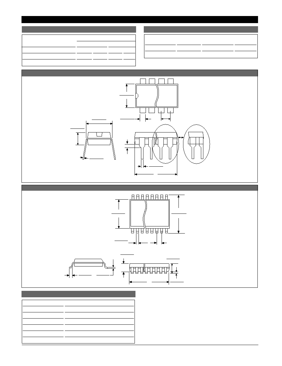
Package Specification
PACKAGE DIMENSIONS IN mm (INCHES)
D
Lead Count
Metric
English
Max
Min
Max
Min
14L PDIP
19.69
18.67
.775
.735
16L SO Wide
10.50
10.10
.413
.398
PACKAGE THERMAL DATA
Thermal Data
14 Lead
16 Lead
PDIP
SO Wide
R
JC
typ
48
23
∞C/W
R
JA
typ
85
105
∞C/W
CS290/291
Ordering Information
Part Number
Description
CS290N14
14L PDIP
CS291N14
14L PDIP
CS290DW16
16 Lead SO Wide
CS290DWR16
16 Lead SO Wide (tape & reel)
CS291DW16
16 Lead SO Wide
CS291DWR16
16 Lead SO Wide (tape & reel)
Cherry Semiconductor Corporation reserves the right to
make changes to the specifications without notice. Please
contact Cherry Semiconductor Corporation for the latest
available information.
Plastic DIP (N); 300 mil wide
0.39 (.015)
MIN.
2.54 (.100) BSC
1.77 (.070)
1.14 (.045)
D
Some 8 and 16 lead
packages may have
1/2 lead at the end
of the package.
All specs are the same.
.203 (.008)
.356 (.014)
REF: JEDEC MS-001
3.68 (.145)
2.92 (.115)
8.26 (.325)
7.62 (.300)
7.11 (.280)
6.10 (.240)
.356 (.014)
.558 (.022)
Surface Mount Wide Body (DW); 300 mil wide
1.27 (.050) BSC
7.60 (.299)
7.40 (.291)
10.65 (.419)
10.00 (.394)
D
0.32 (.013)
0.23 (.009)
1.27 (.050)
0.40 (.016)
REF: JEDEC MS-013
2.49 (.098)
2.24 (.088)
0.51 (.020)
0.33 (.013)
2.65 (.104)
2.35 (.093)
0.30 (.012)
0.10 (.004)