 | –≠–ª–µ–∫—Ç—Ä–æ–Ω–Ω—ã–π –∫–æ–º–ø–æ–Ω–µ–Ω—Ç: CS8101YD8 | –°–∫–∞—á–∞—Ç—å:  PDF PDF  ZIP ZIP |

The CS8101 is a precision 5V
micropower voltage regulator with
very low quiescent current (70µA
typ at 100µA load). The 5V output is
accurate within ±2% and supplies
100mA of load current with a typi-
cal dropout voltage of only 400mV.
Microprocessor control logic
includes an
input and an
active
. This combination of
low quiescent current, outstanding
regulator performance and control
logic makes the CS8101 ideal for
any battery operated, microproces-
sor controlled equipment.
The active
circuit includes
hysteresis, and operates correctly at
an output voltage as low as 1V. The
function is activated during
the power up sequence or during
normal operation if the output
voltage drops outside the regulation
limits by more than 200mV typ. The
logic level compatible
input allows the user to put the reg-
ulator into a shutdown mode where
it draws only 20µA typical of quies-
cent current.
The regulator is protected against
reverse battery, short circuit, over
voltage, and thermal overload con-
ditions. The device can withstand
load dump transients making it
suitable for use in automotive envi-
ronments.
The CS8101 is functionally equiva-
lent to the National Semiconductor
LP2951 series low current regula-
tors.
ENABLE
RESET
RESET
RESET
ENABLE
1
Features
Error
Amplifier
Reset
Comparator
Thermal
Protection
Over
Voltage
Shutdown
V
IN
Gnd
V
OUT
+
-
Bandgap
Reference
+ -
Current Limit
Sense
Current Source
(Circuit Bias)
V
OUT
Sense
RESET
ENABLE
Internally connected
on 5 lead TO-220
s
5V ±2% Output
s
Low 70µA Quiescent
Current
s
Active
s
Input for
ON/OFF and Active/Sleep
Mode Control
s
100mA Output Current
Capability
s
Fault Protection
+60V Peak Transient
Voltage
-15V Reverse Voltage
Short Circuit
Thermal Overload
s
Low Reverse Current
(Output to Input)
ENABLE
RESET
Package Options
CS8101
Micropower 5V, 100mA Low Dropout
Linear Regulator with RESET and ENABLE
CS8101
Description
Block Diagram
1
V
OUT
V
OUT
Sense
ENABLE
Gnd
V
IN
NC
NC
RESET
5L TO-220
Tab (Gnd)
1. V
OUT
2.
3. Gnd
4.
5. V
IN
RESET
ENABLE
Other Packages: D
2
PAK (consult factory)
8L SOIC
V
OUT
V
IN
NC
NC
RESET
1
Gnd
Gnd
Gnd
Gnd
Gnd
Gnd
Gnd
Gnd
ENABLE
NC
NC
NC
NC
NC
NC
NC
20L SOIC Wide
(Internally Fused Leads)
Rev. 4/9/99
Cherry Semiconductor Corporation
2000 South County Trail, East Greenwich, RI 02818
Tel: (401)885-3600 Fax: (401)885-5786
Email: info@cherry-semi.com
Web Site: www.cherry-semi.com
A Company
®

2
Power Dissipation.............................................................................................................................................Internally Limited
Transient Peak Voltage (46V Load Dump) ..................................................................................................................-15V, 60V
Output Current .................................................................................................................................................Internally Limited
ESD Susceptibility (Human Body Model) ..............................................................................................................................2kV
Operating Temperature..........................................................................................................................................-40°C to 125°C
Junction Temperature .............................................................................................................................................-40°C to 150°C
Storage Temperature ................................................................................................................................................-55C to 150°C
Lead Temperature Soldering Wave Solder (through hole styles only) ..........................................10 sec. max, 260°C peak
Reflow (SMD styles only) ..........................................60 sec. max above 183°C, 230°C peak
Electrical Characteristics:
6V ≤ V
IN
≤ 26V, I
OUT
= 1mA, -40 ≤ T
A
≤ 125, -40 ≤ T
J
≤ 150°C unless otherwise specified.
PARAMETER
TEST CONDITIONS
MIN
TYP
MAX
UNIT
CS8101
Absolute Maximum Ratings
s Output Stage
Output Voltage, V
OUT
9V < V
IN
< 16V, 100µA ≤ I
OUT
≤ 100mA
4.90
5.00
5.10
V
6V ≤ V
IN
≤ 26V, 100µA ≤ I
OUT
≤ 100mA
4.85
5.00
5.15
V
Dropout Voltage (V
IN
-V
OUT
)
I
OUT
= 100mA
400
600
mV
I
OUT
= 100µA
100
150
mV
Load Regulation
V
IN
= 14V, 100µA ≤ I
OUT
≤ 100mA
5
50
mV
Line Regulation
6V < V < 26V, I
OUT
= 1mA
5
50
mV
Quiescent Current, (I
Q
)
Active Mode
I
OUT
= 100µA, V
IN
= 6V
70
140
µA
I
OUT
= 50mA
4
6
mA
I
OUT
≤ 100mA
12
20
mA
Sleep Mode
V
OUT
= OFF, V
IN
= 6V, V
= 2V
20
50
µA
Ripple Rejection
7 ≤ V
IN
≤ 17V, I
OUT
= 100mA, f = 120Hz
60
75
dB
Current Limit
105
200
mA
Short Circuit Output Current
V
OUT
= 0V
25
125
mA
Thermal Shutdown
150
180
°C
Overvoltage Shutdown
V
OUT
≤ 1V
30
34
38
V
Reverse Current
V
OUT
= 5V, V
IN
= 0V
100
200
µA
s Enable Input (
)
Threshold
HIGH
(V
OUT
OFF)
1.4
2.0
V
LOW
(V
OUT
ON)
0.6
1.4
V
Input Current
V
= 2.4V
30
100
µA
s Reset Function (
)
Threshold
HIGH (V
RH
)
V
OUT
Increasing
4.525
4.75
V
OUT
- 0.05
V
LOW (V
RL
)
V
OUT
Decreasing
4.500
4.700
V
OUT
- 0.075
V
Hysteresis
(HIGH - LOW)
25
50
100
mV
Reset Output Leakage
V
OUT
≥ V
RH
25
µA
= HIGH
Output Voltage
Low (V
RLO
)
1V ≤ V
OUT
≤ V
RL
0.1
0.4
V
R
= 10K
Low (VRpeak)
V
OUT
, Power up, Power down
0.6
1.0
V
RESET
RESET
RESET
RESET
RESET
ENABLE
ENABLE
ENABLE
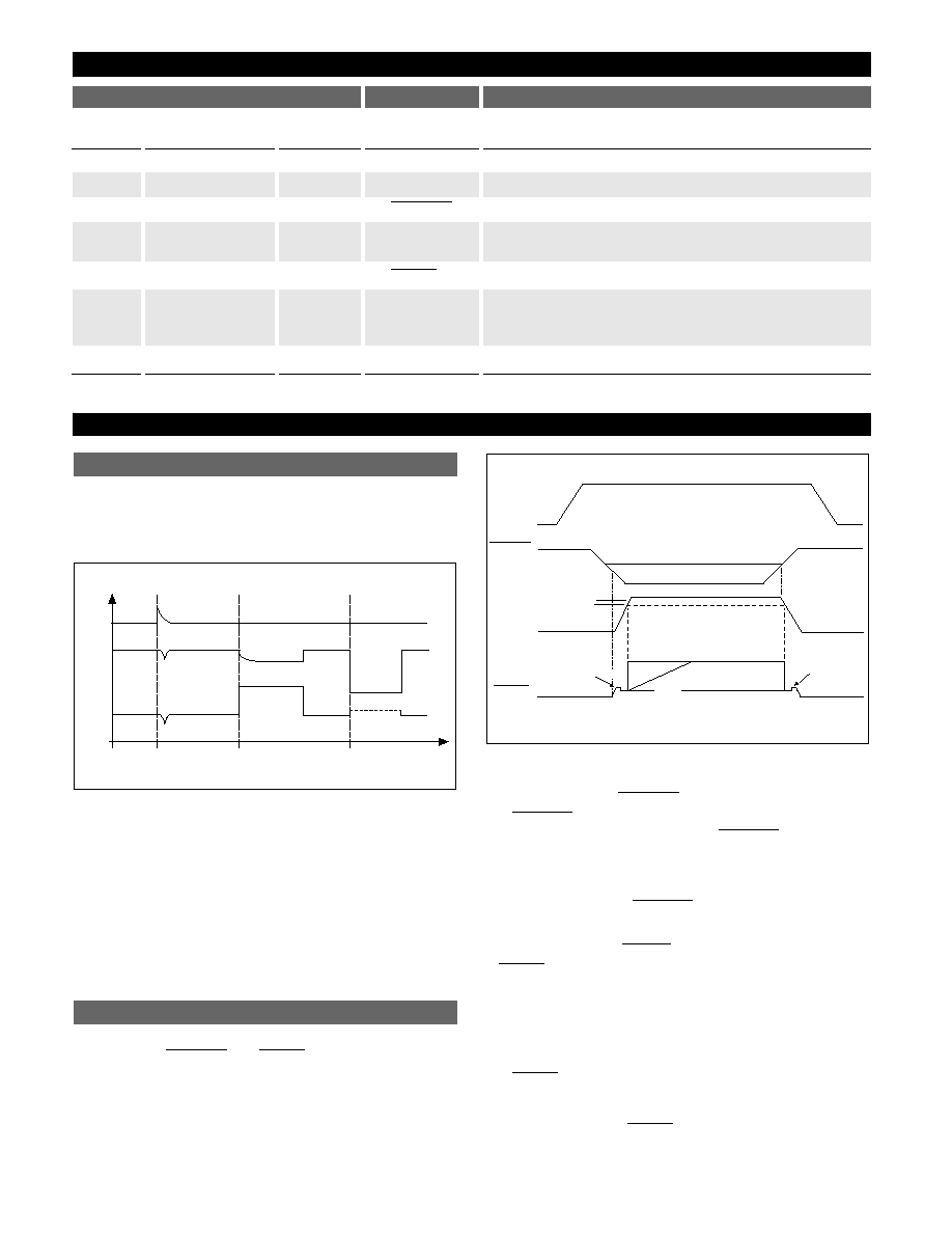
Output Stage Protection
The output stage is protected against overvoltage, short
circuit and thermal runaway conditions (Figure 1).
Figure 1. Typical Circuit Waveforms for Output Stage Protection.
If the input voltage rises above 30V (e.g. load dump), the out-
put shuts down. This response protects the internal circuitry
and enables the IC to survive unexpected voltage transients.
Should the junction temperature of the power device exceed
180˚C (typ) the load current capability is reduced thereby
preventing thermal overload. This thermal management
function is an effective means to prevent die overheating
since the load current is the principle heat source in the IC.
The CS8101 contains two microprocessor compatible con-
trol functions:
and
(Figure 2).
Figure 2. Circuit Waveform
Function
The
function switches the output transistor ON
and OFF. When the voltage on the
lead exceeds
1.4V typ, the output pass transistor turns off, leaving a
high impedance facing the load. The IC will remain in
Sleep mode, drawing only 50µA, until the voltage on this
input drops below the
threshold.
Function
A
signal (low voltage) is generated as the IC pow-
ers up until V
OUT
is within 250mV of the regulated output
voltage, or when V
OUT
drops out of regulation,and is
lower than 300mV below the regulated output voltage. A
hysteresis of 50mV is included in the function to minimize
oscillations.
The
output is an open collector NPN transistor,
controlled by a low voltage detection circuit. The circuit is
functionally independent of the rest of the IC thereby
guaranteeing that the
signal is valid for V
OUT
as low
as 1V.
RESET
RESET
RESET
RESET
ENABLE
ENABLE
ENABLE
ENABLE
(1) = NO RESET DELAY CAPACITOR
(2) = WITH RESET DELAY CAPACITOR
FOR 7V < V
IN
< 26V
V
OUT
V
RH
ENABLE
V
RL
(1)
(2)
V
IN
V
IN
H
VR
PEAK
VR
LO
VR
PEAK
RESET
RESET
ENABLE
Regulator Control Functions
IOUT
VOUT
VIN
Load
Dump
Short
Circuit
Current
Limit
> 30V
Voltage Reference and Output Circuitry
3
CS8101
Package Lead Description
PACKAGE LEAD #
LEAD SYMBOL
FUNCTION
Circuit Description
8 Lead
20 Lead SOIC
5 Lead
SOIC
(Internally Fused Leads)
TO-220
8
19
5
V
IN
Input voltage.
1
20
1
V
OUT
5V, ±2%, 100mA output.
3
1
2
Logic level switches output off when toggled HIGH.
4
4,5,6,7
3
Gnd
Ground. All Gnd leads must be connected to Ground.
14,15,16,17
5
10
4
Active reset (accurate to V
OUT
≥ 1V).
2
V
OUT
Sense
Kelvin connection which allows remote sensing of out-
put voltage for improved regulation. If remote sensing
is not required, connect to V
OUT
.
6,7
2,3,8,9,11,12,13,18
NC
No Connection.
RESET
ENABLE
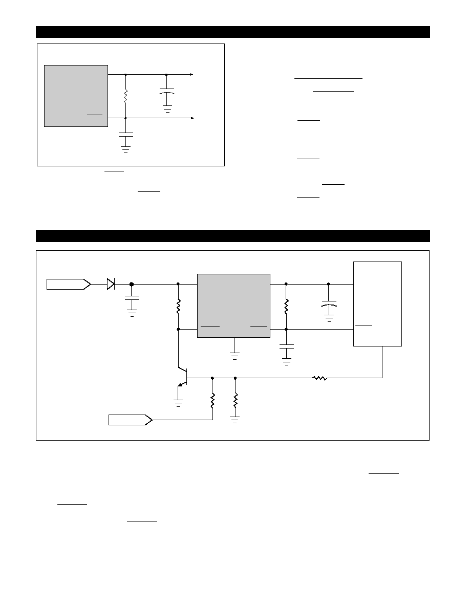
Figure 3. RC Network for
Delay
An external RC network on the
lead (Figure 3) pro-
vides a sufficiently long delay for most microprocessor
based applications. RC values can be chosen using the
following formula:
–t
Delay
R
TOT
C
RST
=
[
ln
]
where: R
RST
=
Delay resistor
R
IN
= µP port impedance
R
TOT
= R
RST
in parallel with R
IN
C
RST
=
Delay capacitor
t
Delay
= desired delay time
V
RST
= V
SAT
of
lead (0.7V @ turn - ON)
V
T
=
threshold
RESET
RESET
RESET
RESET
)
V
T
– V
OUT
V
RST
– V
OUT
(
RESET
RESET
RESET
CS8101
V
OUT
C
RST
R
RST
C
OUT
5V to
mP
and
System
Power
to
mP
RESET
Port
The circuit depicted in Figure 4 lets the microprocessor
control its power source, the CS8101 regulator. An I/O
port on the µP and the SWITCH port are used to drive the
base of Q1. When Q1 is driven into saturation, the voltage
on the
lead falls below its lower threshold. The
regulator’s output is enabled. When the drive current is
removed, the voltage on the
lead rises, the out-
put is switched off and the IC moves into Sleep mode
where it draws 50µA (max).
By coupling these two controls with the
lead, the
system has added flexibility. Once the system is running,
the state of the SWITCH is irrelevant as long as the I/O
port continues to drive Q1. The microprocessor can turn
off its own power by withdrawing drive current, once the
SWITCH is open. This software control at the I/O port
allows the microprocessor to finish key housekeeping
functions before power is removed.
The logic options are summarized in Table 1.
ENABLE
ENABLE
ENABLE
4
CS8101
Applications Notes
Circuit Description: continued
0.1
mF
V
IN
Gnd
CS8101
V
OUT
500k
W
Q
1
500k
W
100k
W
100k
W
C
RST
R
RST
C
OUT
V
CC
I/O Port
mP
SWITCH
V
BAT
RESET
ENABLE
RESET
Figure 4. Microprocessor Control of CS8101 using external switching transistor Q
1
.
The I/O port of the microprocessor typically provides
50µA to Q1. In automotive applications the SWITCH is
connected to the ignition switch.
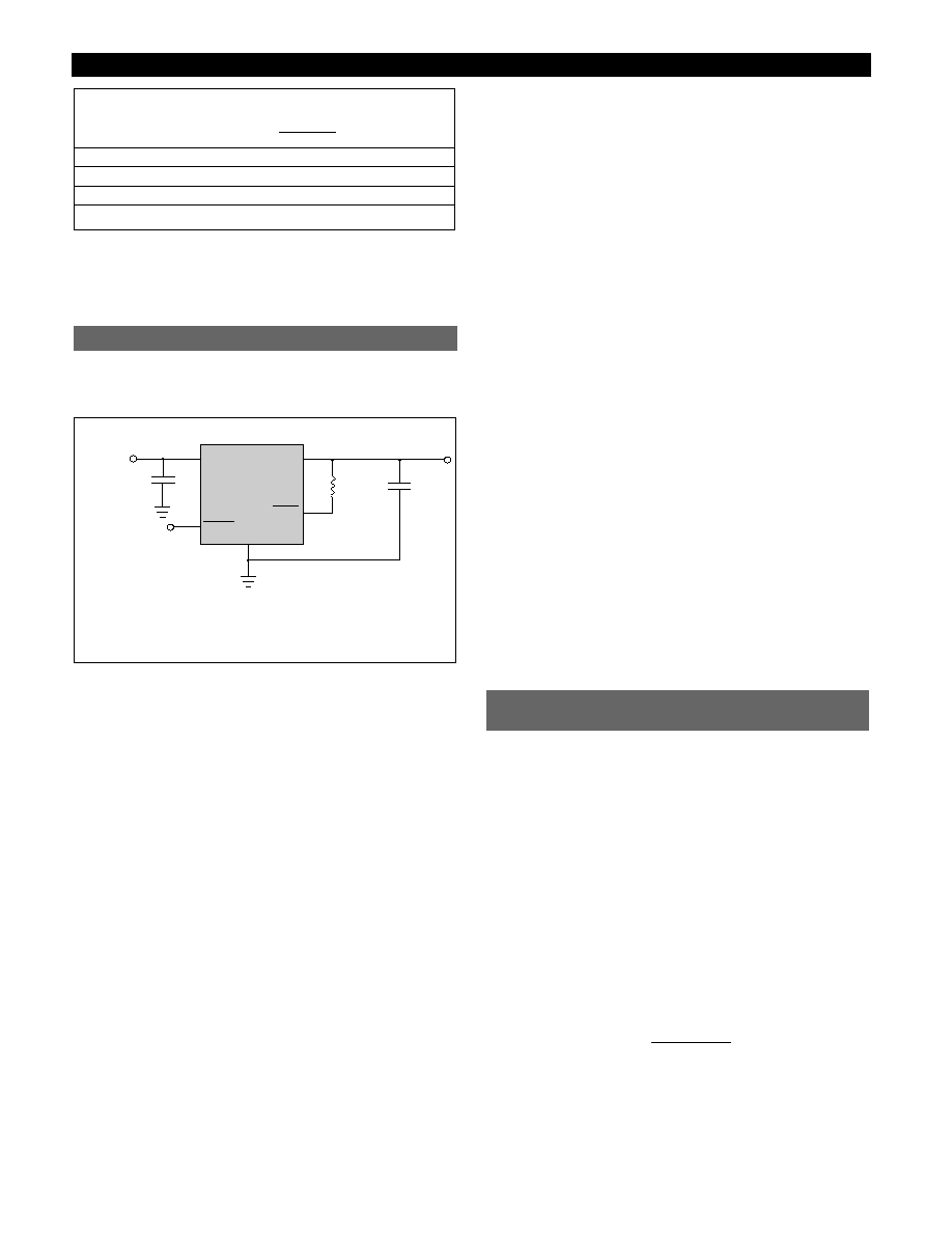
The output or compensation capacitor helps determine
three main characteristics of a linear regulator: start-up
delay, load transient response and loop stability.
Figure 5. Test and application circuit showing output compensation.
The capacitor value and type should be based on cost,
availability, size and temperature constraints. A tantalum
or aluminum electrolytic capacitor is best, since a film or
ceramic capacitor with almost zero ESR can cause instabili-
ty. The aluminum electrolytic capacitor is the least expen-
sive solution, but, if the circuit operates at low tempera-
tures (-25°C to -40°C), both the value and ESR of the
capacitor will vary considerably. The capacitor manufac-
turers data sheet usually provides this information.
The value for the output capacitor C
OUT
shown in Figure 5
should work for most applications, however it is not nec-
essarily the optimized solution.
To determine an acceptable value for C
OUT
for a particular
application, start with a tantalum capacitor of the recom-
mended value and work towards a less expensive alterna-
tive part.
Step 1:
Place the completed circuit with a tantalum capac-
itor of the recommended value in an environmental cham-
ber at the lowest specified operating temperature and
monitor the outputs with an oscilloscope. A decade box
connected in series with the capacitor will simulate the
higher ESR of an aluminum capacitor. Leave the decade
box outside the chamber, the small resistance added by the
longer leads is negligible.
Step 2:
With the input voltage at its maximum value,
increase the load current slowly from zero to full load
while observing the output for any oscillations. If no oscil-
lations are observed, the capacitor is large enough to
ensure a stable design under steady state conditions.
Step 3:
Increase the ESR of the capacitor from zero using
the decade box and vary the load current until oscillations
appear. Record the values of load current and ESR that
cause the greatest oscillation. This represents the worst
case load conditions for the regulator at low temperature.
Step 4
: Maintain the worst case load conditions set in step
3 and vary the input voltage until the oscillations increase.
This point represents the worst case input voltage conditions.
Step 5:
If the capacitor is adequate, repeat steps 3 and 4
with the next smaller valued capacitor. A smaller capacitor
will usually cost less and occupy less board space. If the
output oscillates within the range of expected operating
conditions, repeat steps 3 and 4 with the next larger stan-
dard capacitor value.
Step 6:
Test the load transient response by switching in
various loads at several frequencies to simulate its real
working environment. Vary the ESR to reduce ringing.
Step 7:
Remove the unit from the environmental chamber
and heat the IC with a heat gun. Vary the load current as
instructed in step 5 to test for any oscillations.
Once the minimum capacitor value with the maximum
ESR is found, a safety factor should be added to allow for
the tolerance of the capacitor and any variations in regula-
tor performance. Most good quality aluminum electrolytic
capacitors have a tolerance of ±20% so the minimum value
found should be increased by at least 50% to allow for this
tolerance plus the variation which will occur at low tem-
peratures. The ESR of the capacitor should be less than
50% of the maximum allowable ESR found in step 3 above.
The maximum power dissipation for a single output regu-
lator (Figure 6) is:
P
D(max)
= {V
IN(max)
- V
OUT(min)
}I
OUT(max)
+ V
IN(max)
I
Q
(1)
where:
V
IN(max)
is the maximum input voltage,
V
OUT(min)
is the minimum output voltage,
I
OUT(max)
is the maximum output current for the applica-
tion, and
I
Q
is the quiescent current the regulator consumes at
I
OUT(max)
.
Once the value of P
D(max)
is known, the maximum permis-
sible value of R
QJA
can be calculated:
R
QJA
=
(2)
The value of R
QJA
can then be compared with those in
the package section of the data sheet. Those packages with
R
QJA
's less than the calculated value in equation 2 will keep
the die temperature below 150°C.
150°C - T
A
P
D
Calculating Power Dissipation
in a Single Output Linear Regulator
RESET
CS8101
V
OUT
R
RST
C
OUT**
10
mF
ENABLE
V
IN
C
IN
*
0.1
mF
*C
IN
required if regulator is located far from the power supply filter.
** C
OUT
required for stability. Capacitor must operate at minimum
temperature expected.
Stability Considerations
Table 1. Logic Control of CS8101 Output
Microprocessor
I/O drive
Switch
ENABLE
Output
ON
Closed
LOW
ON
Open
LOW
ON
OFF
Closed
LOW
ON
Open
HIGH
OFF
5
CS8101
Application Notes: continued