 | –≠–ª–µ–∫—Ç—Ä–æ–Ω–Ω—ã–π –∫–æ–º–ø–æ–Ω–µ–Ω—Ç: CS9236-CQ | –°–∫–∞—á–∞—Ç—å:  PDF PDF  ZIP ZIP |
Preliminary Product Information
This document contains information for a new product. Crystal
Semiconductor reserves the right to modify this product without notice.
MAY `97
DS214PP11
1
Copyright
©
Crystal Semiconductor Corporation 1997
(All Rights Reserved)
Crystal Semiconductor Corporation
P.O. Box 17847, Austin, Texas 78760
(512) 445 7222 FAX: (512) 445 7581
http://www.crystal.com
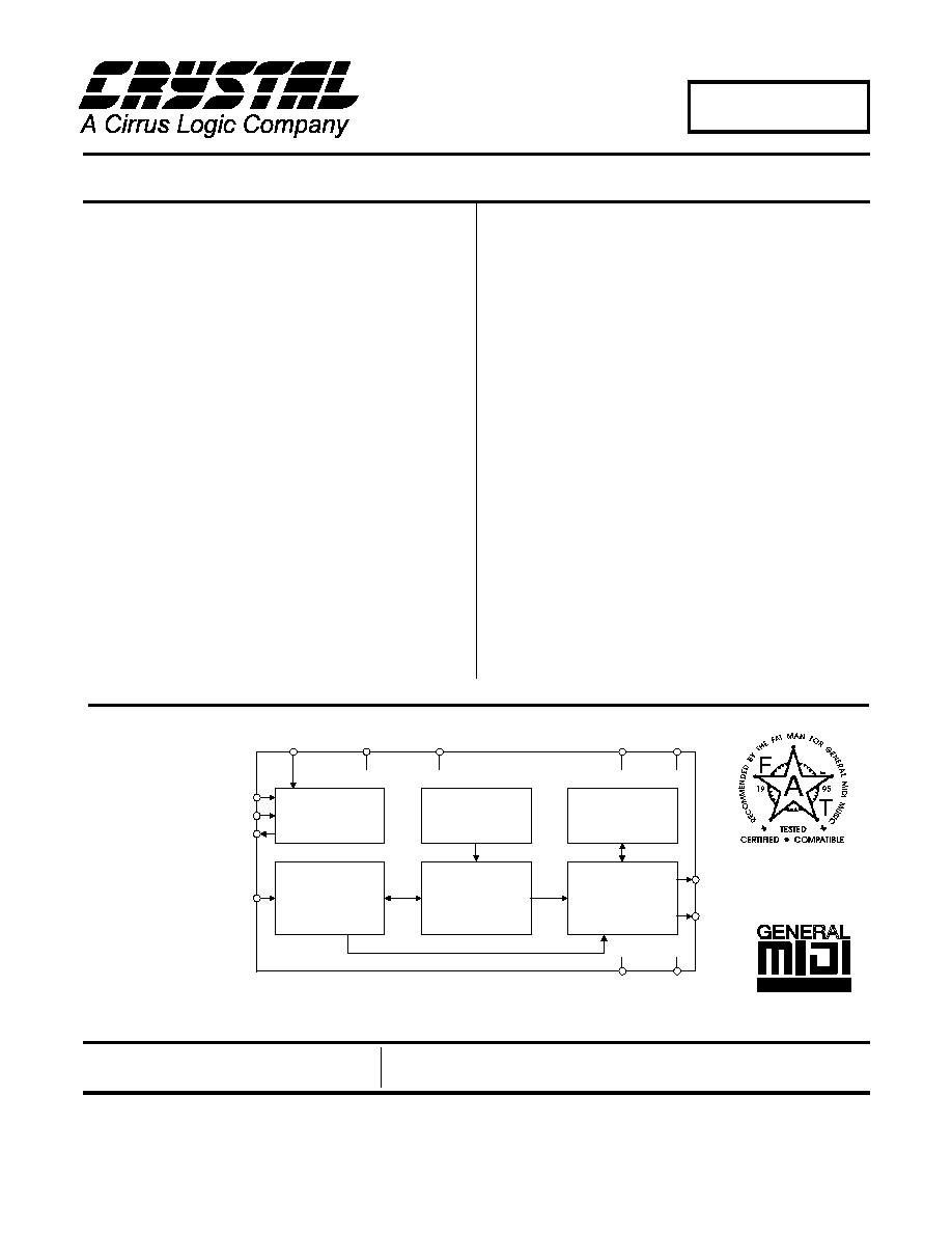
CS9236
Single-Chip Wavetable Music Synthesizer
Features
∑
Single low-cost device includes MIDI
controller, synthesis engine, effects
processing, RAM, and sample ROM
∑
General MIDI (GM) compliant
∑
32-note polyphony at 44.1kHz rate
∑
Independent reverb and chorus levels
for each MIDI channel
∑
+3.3V supply, +5V tolerant inputs
∑
Fully static power-down capability
∑
Simple to design in - Serial MIDI in,
Stereo digital audio out
∑
Digital audio output directly Interfaces
with the CS4236B/37B/38B and
CS4333
General Description
The CS9236 is a complete General MIDI wavetable mu-
sic synthesizer on a single integrated circuit. The MIDI
interpreter, synthesis engine, effects processing, and all
RAM and ROM memories (including the wavetable sam-
ple ROM) are included on-chip. This all-digital device
receives a standard serial MIDI data stream, and outputs
a stereo 16-bit digital audio stream at 44.1kHz. The
CS9236 digital audio output is directly compatible with
the Crystal CS4236B/37B/38B multimedia CODECs,
and with the CS4333 DAC.
The CS9236 features a high quality General MIDI sam-
ple set including 128 melodic instruments and 47
percussion sounds. The synthesis engine is capable of
generating up to 32 simultaneous notes. Digital rever-
beration and chorusing effects are included on-chip.
The CS9236 is the ideal low-cost General MIDI synthe-
sizer solution for a number of applications, including
multimedia PCs, game machines, karaoke, and low-cost
musical instruments and MIDI sound modules.
ORDERING INFORMATION
CS9236-CL
0∞ to 70∞C
28-pin PLCC
CS9236-CQ
0∞ to 70∞C
44-pin TQFP
MIDI Interpreter
Synthesis Engine
Effects Processor
Clock Generation
& Control
Sample ROM
Effects RAM
SOUT
LRCLK
VDD2
____
PDN
____
RST
GND1
TEST
MCLK5I
MIDI_IN
VDD1
GND2
XTAL3I
XTALO

CS9236
2
DS214PP11
TABLE OF CONTENTS
RECOMMENDED OPERATING CONDITIONS .............................................................................4
SWITCHING CHARACTERISTICS ..................................................................................................4
DIGITAL CHARACTERISTICS ........................................................................................................6
ABSOLUTE MAXIMUM RATINGS ......................................................................................... 6
GENERAL DESCRIPTION .................................................................................................................7
CS9236/CS4236B/37B/38B Typical Connections ......................................................................7
CS9236/CS4333 Typical Connections ........................................................................................8
CS9236 Clocks and Timing Generation ....................................................................................9
Power-Down Modes .....................................................................................................................9
Digital Audio Interface ................................................................................................................9
Reset ..............................................................................................................................................9
GENERAL MIDI (GM) MELODIC INSTRUMENTS AND PERCUSSION SOUNDS ..............10
MIDI IMPLEMENTATION ...............................................................................................................13
Channel Voice Messages ...........................................................................................................13
Control Change Messages .........................................................................................................13
Registered Parameters ..............................................................................................................13
Channel Mode Messages ...........................................................................................................13
System Realtime Messages ........................................................................................................14
System Exclusive Messages .......................................................................................................14
Message Definitions ...................................................................................................................16
Channel Voice Messages .....................................................................................................16
NOTE ON ..........................................................................................................................16
NOTE OFF ........................................................................................................................16
PROGRAM CHANGE ......................................................................................................17
CHANNEL PRESSURE (Channel Aftertouch) ................................................................17
PITCH BEND CHANGE ..................................................................................................18
Control Change Messages...................................................................................................19
MODULATION WHEEL (CONTROLLER 1) ................................................................19
DATA ENTRY (CONTROLLERS 6 and 38)...................................................................19
VOLUME (CONTROLLER 7) .........................................................................................19
PAN (CONTROLLER 10) ................................................................................................20
EXPRESSION (CONTROLLER 11) ................................................................................20
DAMPER PEDAL/SUSTAIN (CONTROLLER 64)........................................................20
SOSTENUTO (CONTROLLER 66) .................................................................................21
EFFECT 1 DEPTH/REVERB SEND LEVEL (CONTROLLER 91) ...............................21
EFFECT 3 DEPTH/CHORUS SEND LEVEL (CONTROLLER 93) ..............................21
REGISTERED PARAMETER NUMBER (RPN) (CONTROLLERS 100 and 101) .......22
Registered Parameters ........................................................................................................23
PITCH BEND SENSITIVITY (RPN 00) ..........................................................................23
FINE TUNING (RPN 01)..................................................................................................23
COARSE TUNING (RPN 02)...........................................................................................24
Channel Mode Messages.....................................................................................................25
ALL SOUNDS OFF (Controller 120) ...............................................................................25
RESET ALL CONTROLLERS (Controller 121)..............................................................25
ALL NOTES OFF (Controller 123) ..................................................................................25
OMNI MODE OFF (Controller 124) ................................................................................25
OMNI MODE ON (Controller 125) ..................................................................................26
MONO MODE ON (Controller 126) ................................................................................26
POLY MODE ON (Controller 127) ..................................................................................26
System Real Time Messages ...............................................................................................27

CS9236
DS214PP11
3
ACTIVE SENSING........................................................................................................... 27
SYSTEM RESET .............................................................................................................. 27
System Exclusive Messages ................................................................................................ 28
ENABLE RECOGNITION OF MIDI CHANNEL PRESSURE ...................................... 28
DISABLE RECOGNITION OF MIDI CHANNEL PRESSURE..................................... 28
ENABLE TEST TONE ..................................................................................................... 29
DISABLE TEST TONE .................................................................................................... 29
PIN DESCRIPTIONS .......................................................................................................................... 30
CS9236
4
DS214PP11
RECOMMENDED OPERATING CONDITIONS
(DGND=0V, all voltages with respect to 0V.)
Per JEDEC Standard No. 8-A for LVCMOS
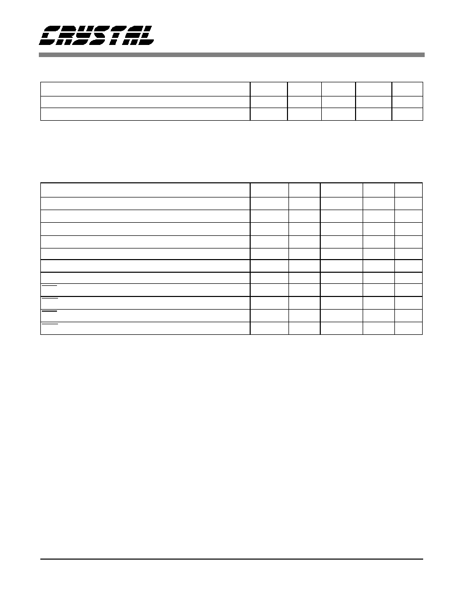
SWITCHING CHARACTERISTICS
(T
A
= 0 - 70 ∞C; VD = +3.3V ± .3V, outputs loaded with 30pF;
Input Levels: Logic 0 = 0V, Logic 1 = 5V) (Note 1)
Notes: 1. XTAL3I input level is VD.
2. LRCLK frequency is equal to f
ck
/384. Optimum synthesized pitch and envelope characteristics will be
achieved when CLKIN frequency, f
ck
, is equal to 16.9344 MHz (LRCLK frequency, f
lrw
= 44.1 kHz).
Specifications are subject to change without notice.
Parameter
Symbol
Min
Typ
Max
Units
Power Supply
VD
3.0
3.3
3.6
V
Operating Ambient Temperature
T
A
0
25
70
∞C
Parameter
Symbol
Min
Typ
Max
Units
Input clock (CLKIN) frequency
(Note 2)
f
ck
16.92
16.9344
16.95
MHz
CLKIN low time
t
ckl
23.6
-
-
ns
CLKIN high time
t
ckh
23.6
-
-
ns
LRCLK frequency
(Note 2)
f
lrw
-
44.1
-
kHz
LRCLK duty cycle
47
50
53
%
SOUT delay from LRCLK rising/falling edge
t
sdsk
-
-
10
ns
MIDI_IN Bit Rate (Asynchronous to MCLK5I or XTAL3I)
30937.5
31250
31562.5
bits/s
RST pulse width low
t
rpw
500
-
-
ns
PDN pulse width low
t
ppw
500
-
-
ns
RST high to valid MIDI input
t
rdr
300
-
-
ms
PDN high to valid MIDI input
t
rdp
0.15
-
-
ms
CS9236
DS214PP11
5
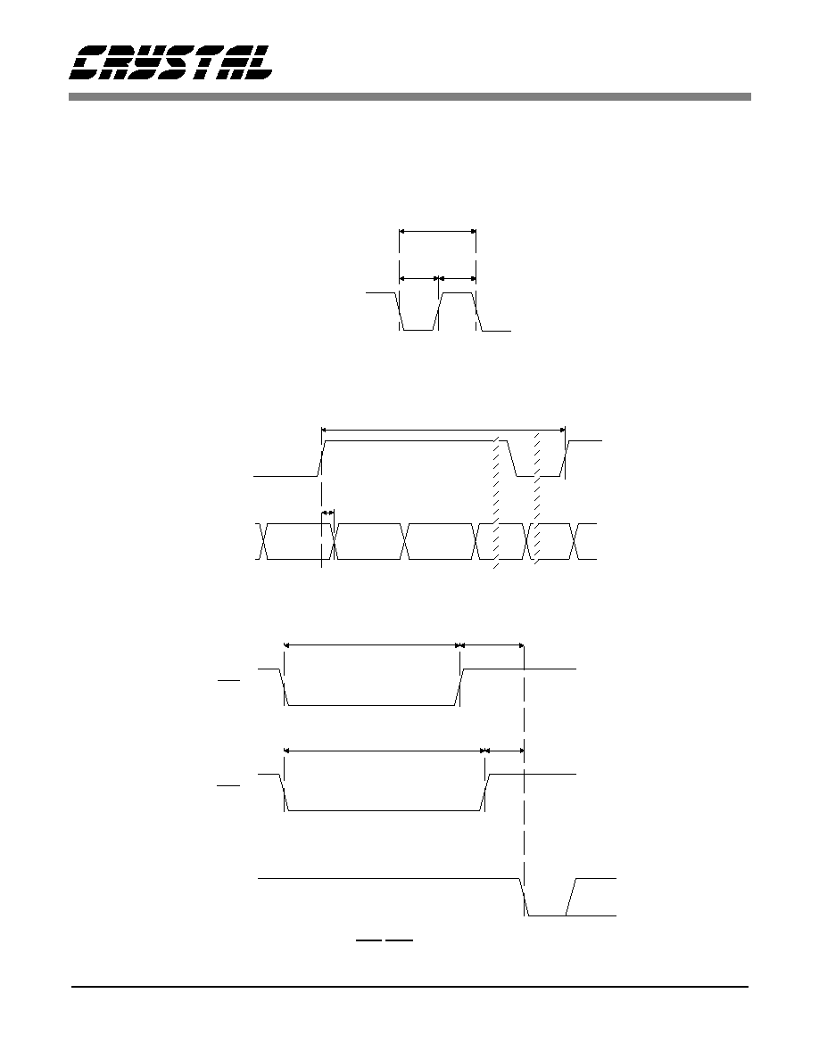
MCLK_IN
ck
(f )
-1
tckl
tckh
Master Clock Timing
SOUT
LRCLK
sdsk
t
(f )
-1
lrw
Digital Audio Port Timing
RST
t rpw
PDN
t ppw
MIDI_IN
t rdr
t rdp
Start Bit
MIDI
DATA
RST/PDN Timing
CS9236
6
DS214PP11
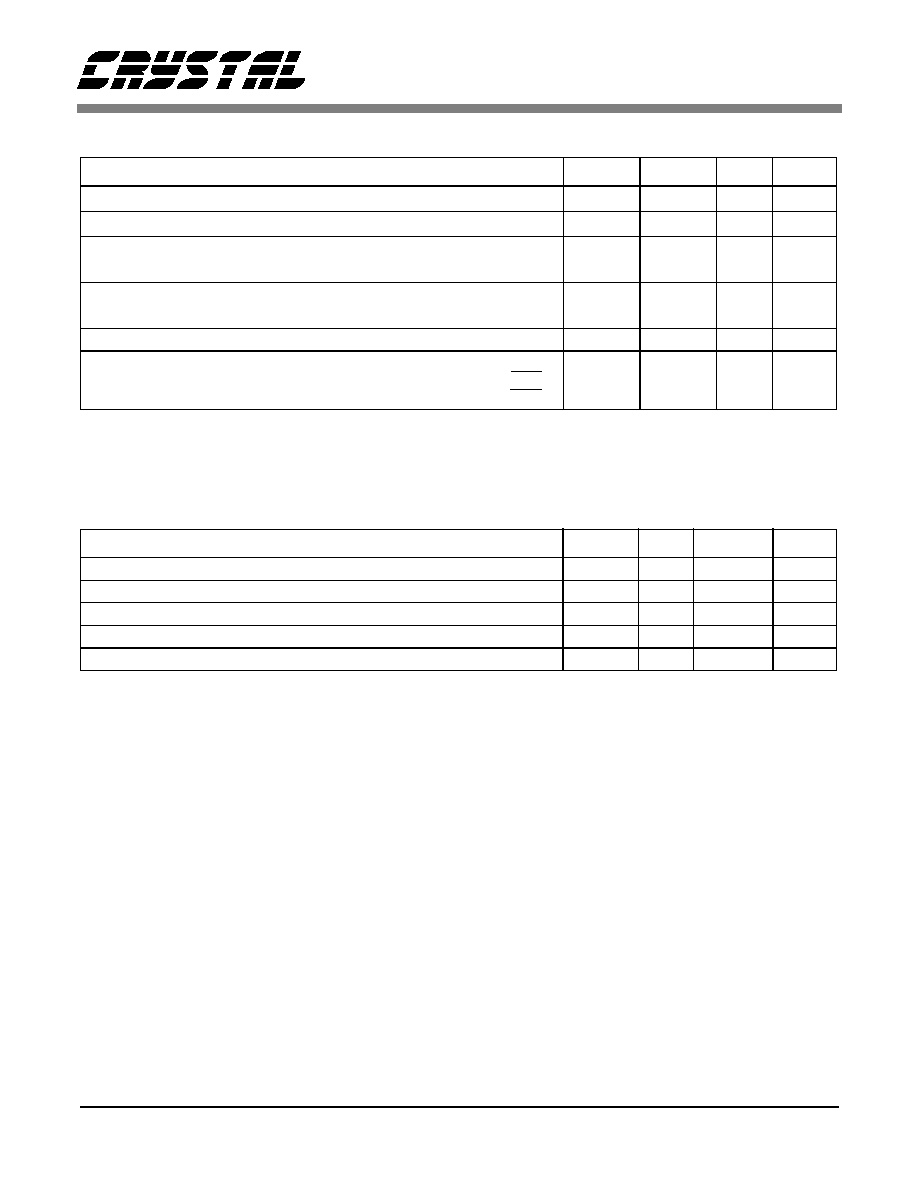
DIGITAL CHARACTERISTICS
(T
A
= 25 ∞C; VD = +3.3V)
Notes: 3. JEDEC Standard No. 8-A for LVCMOS, copyright Electronic Industries Association 1994, specifies
VD+0.3 max. CS9236 digital inputs are +5V tolerant.
ABSOLUTE MAXIMUM RATINGS
(DGND = 0V, all voltages with respect to 0V)
Warning:
Operation beyond these limits may result in permanent damage to the device.
Normal operation is not guaranteed at these extremes.
Parameter
Symbol
Min
Max
Units
High-level Input Voltage
(Note 3)
V
IH
2.0
-
V
Low-level Input Voltage
V
IL
-0.3
0.8
V
High-level Output Voltage at I
O
= -100µA
at I
O
= -1mA
V
OH
VD - 0.3
VD - 0.5
-
V
Low-level Output Voltage at I
O
= 100µA
at I
O
= 4mA
V
OL
-
-
0.3
0.5
V
Input leakage Current
(Digital Inputs)
-
10
µ
A
Supply Current
(Normal Operation)
(Power Down with RST)
(Power Down with PDN)
-
-
-
150
400
1
mA
µ
A
mA
Parameter
Symbol
Min
Max
Units
Power Supplies
VD
-0.3
4.6
V
Input Current
(Except Supply Pins)
-
±20
mA
Digital Input Voltage
-0.3
5.25
V
Ambient Temperature
(Power Applied)
-55
125
∞C
Storage Temperature
-55
125
∞C
CS9236
DS214PP11
7
GENERAL DESCRIPTION
The CS9236 is a complete 32-note General MIDI music syn-
thesizer with integral digital effects processing in a single de-
vice. This device accepts a standard serial MIDI data stream
at 31.25 kbit/s and generates a stereo digital audio output data
stream at 44.1 ksample/s sampling rate. The device operates
from a single 3.3VDC supply. The digital inputs to the device
are 5V tolerant, allowing direct connection to parts which are
powered from 5V or 3V supplies. The CS9236 has been de-
signed to interface directly with the Crystal Semiconductor
CS4236B/37B/38B Single Chip Audio Systems and with the
CS4333 Stereo D/A Converter (DAC). When the CS9236 is
used in conjunction with the CS4236B/37B/38B, the digital
audio output from the CS9236 is input to the CS4236B/37B/
38B in digital format, so no separate DAC is required. In ap-
plications which require an analog output from the CS9236,
the CS4333 DAC is employed to convert the digital audio
output of the CS9236 into analog format.
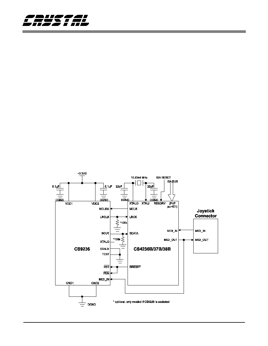
CS9236/CS4236B/37B/38B Typical Connections
The CS9236 combined with the CS4236B/37B/38B provides
a complete ISA Plug-and-Play compatible sound system for
multimedia PC applications. Figure 1 depicts the typical con-
nections between the CS9236 and the CS4236B/37B/38B. In
this application, the CS4236B/37B/38B 16.9344 MHz
MCLK gated clock output drives the CS9236 MCLK5I input,
eliminating the need for a separate quartz crystal circuit.
MIDI messages are sent from the host PC to the CS4237B
over the ISA bus. The CS4236B/37B/38B provides a Plug-
and-Play configurable MPU-401 UART mode-compatible
ISA MIDI interface. The CS4236B/37B/38B MPU-401
UART function transmits the MIDI data received over the
ISA bus to the CS9236 (and to the Joystick MIDI Out pin) in
serial format. The CS9236 interprets the MIDI messages and
generates the appropriate musical sounds. These sounds are
output in serial digital audio format at the CS9236 SOUT pin.
The digital audio output from the CS9236 is input directly
into the CS4236B/37B/38B, eliminating the need for a sepa-
rate DAC.
For more details on using the CS9236 with the CS4236B/
37B/38B, see Application Note 92, "Configuring the
CS423xB/CS9236 Wavetable Interface."
Figure 1. CS9236/CS4236B, CS4237B or CS4238B Typical Connections
CS9236
8
DS214PP11
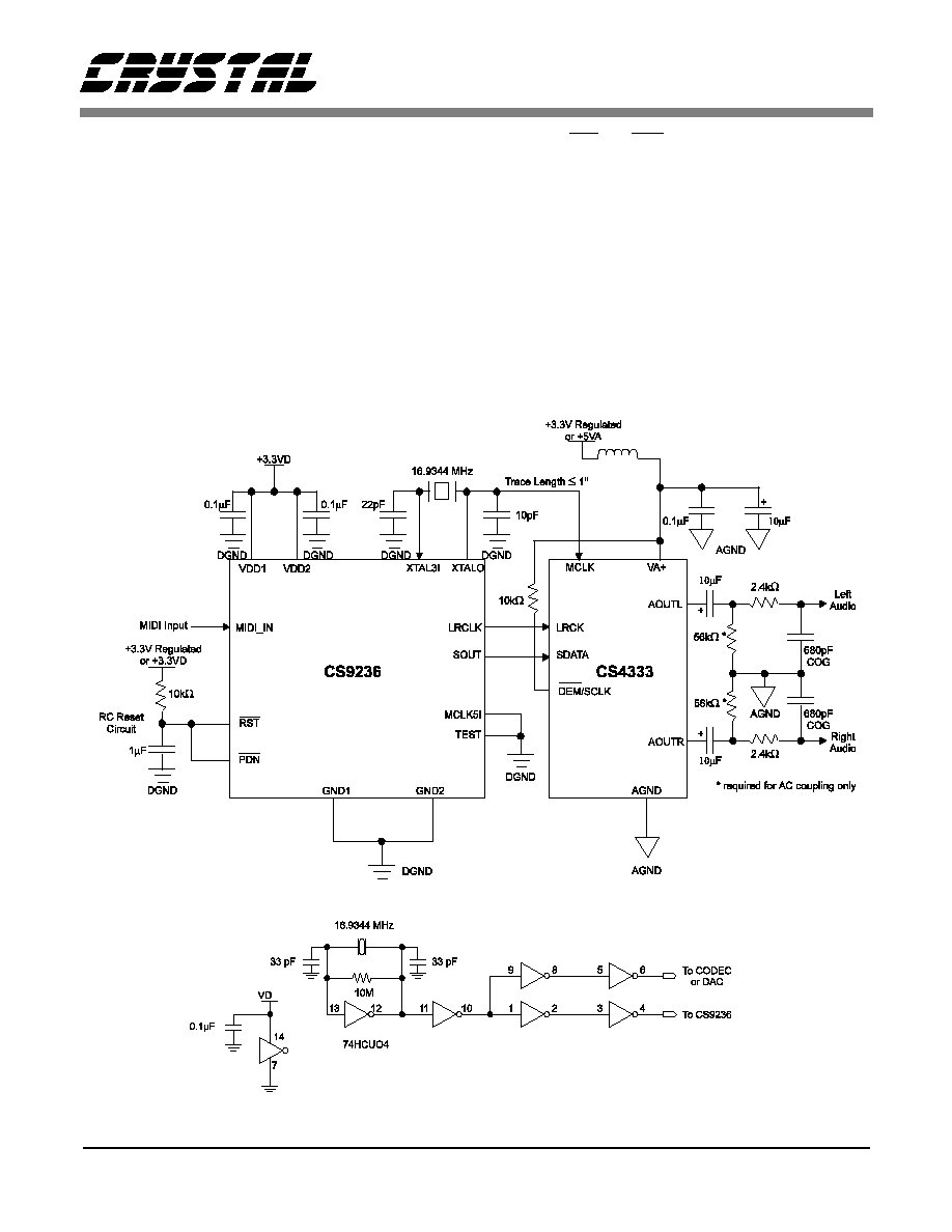
CS9236/CS4333 Typical Connections
In applications which require analog audio output from the
CS9236 synthesizer, the CS4333 Stereo DAC is utilized.
Figure 2 shows typical connections for a stand-alone music
synthesizer application (e.g. low-cost musical keyboards,
MIDI modules, game boxes). In this application the CS9236
digital audio output, SOUT, and the associated clocks, LR-
CLK and XTALO, are input to the CS4333. The CS4333
converts the stereo digital audio data stream into left and right
analog audio outputs, LOUT and ROUT.
Note that the example shown in Figure 2 employs an R-C fil-
ter circuit to generate a reset signal which is applied to both
the CS9236 RST and PDN inputs. In some applications it
may be desirable to control one or both of these control sig-
nals dynamically.
The CS4333 clock input is driven by the CS9236 crystal os-
cillator output pin. The CS9236 must be placed as close as
possible to the CS4333 in order to minimize the length of the
XTALO/MCLK trace. The XTALO capacitor must be 10 pF,
while the XTAL3I capacitor remains the typical 22 pF. If the
CS9236 cannot be placed close to the CS4333, the buffered
crystal circuit shown in Figure 3 or a MicroClock MK1444-
02 clock generator may be used. Do not use separate 16.9344
MHz crystals/clock sources for the synthesizer and DAC.
Figure 2. CS9236/CS4333 Typical Connections.
Figure 3. Buffered Crystal Oscillator Circuit.

CS9236
DS214PP11
9
CS9236 Clocks and Timing Generation
The CS9236 internal timing is derived from one of two pos-
sible sources; the part may be supplied a 16.9344 MHz Mas-
ter Clock signal from an external source, or the timing may be
generated using the on-chip oscillator circuit in conjunction
with an external 16.9344 MHz quartz crystal. When a Master
Clock signal is provided to the CS9236 from an external de-
vice, the Master Clock signal should be connected to the
CS9236 MCLK5I input pin and the XTAL3I input pin is
grounded. When the CS9236 internal timing is generated us-
ing the on-chip oscillator circuit, a 16.9344 MHz quartz crys-
tal is connected between the CS9236 XTAL3I input pin and
the XTALO output pin, and the MCLK5I input pin is ground-
ed. In this case, the XTALO output may also be used as a
384X master clock for the CS9236 digital audio output signal,
SOUT.
Power-Down Modes
The CS9236 provides a fully-static power-down mode of op-
eration. The power-down mode is initiated either by assertion
of the active-low PDN signal, or by gating off of the MCLK5I
input signal (via the CODEC DMCLK bit in CS4236B/7B/8B
applications). In the power-down mode of operation, clock
signals to virtually all of the CS9236 internal circuitry are gat-
ed off to minimize power consumption. The CS9236 device
is fully static, so all internal states and register values will be
retained during power-down, provided that power remains
applied to the device and that the RST signal remains inac-
tive. Power-down operation is terminated either by deasser-
tion of PDN or by gating back on the MCLK5I input signal.
The device will then resume normal operation.
Digital Audio Interface
The CS9236 provides a stereo 16-bit serial digital audio out-
put at a 44.1 ksample/s sampling rate. The CS9236 digital au-
dio output is compatible with the Crystal Semiconductor
CS4236B/37B/38B and CS4333 devices. The digital audio
interface consists of the digital audio output signal, SOUT,
and the associated left/right word clock output, LRCLK.
Transitions of the SOUT and LRCLK signals are synchro-
nous to the CS9236 crystal oscillator output clock, XTALO.
The relationship between the CS9236 SOUT data output and
the LRCLK clock output is indicated in Figure 4.
Reset
The CS9236 is initialized/reset to a known default state using
the RST signal. The RST signal should be applied at power-
on time to initialize the part. Minimum RST pulse width is
500 ns.
Left Channel
Right Channel
15
13 12 11 10 9 8
7 6
5 4
3 2
1
14
0
15
13 12 11 10 9 8
7 6
5 4
3 2 1
14
0
0
LRCLK
SOUT
8-bits
8-bits
Figure 4. Digital Audio Port Format.

CS9236
10
DS214PP11
GENERAL MIDI (GM) MELODIC
INSTRUMENTS AND PERCUSSION
SOUNDS
The CS9236 supports 128 melodic instruments and 47 per-
cussive sounds as specified by the General MIDI Level 1
specification.
MIDI messages generally consist of a single status byte fol-
lowed by one or two data bytes (Real-Time messages and
System Exclusive messages are exceptions). The status byte
is an eight-bit value which indicates the type of message, and
for Channel Voice or Channel Mode messages, the MIDI
channel number to which the message applies. The most sig-
nificant bit of the Status byte is always a "1". The most sig-
nificant bit a MIDI Data byte is always a "0", so a data byte
contains only 7 bits of useful data. Status bytes and Data
bytes for functions not implemented are ignored.
In General MIDI (GM) instruments like the CS9236, MIDI
channels 1 - 9 and 11 - 16 are used for melodic instruments.
On MIDI channels 1 - 9 and 11 - 16, the MIDI Program
Change message is used to select the instrument to be used on
a specific MIDI channel. The General MIDI melodic instru-
ment set is listed in Table 1.
The General MIDI system reserves channel 10 for key-
mapped percussion sounds. The General MIDI percussion
map defines the association of percussion sounds to key num-
bers (note numbers) for use on channel 10. Program Change
messages on channel 10 are ignored. The CS9236 includes
default settings for the PAN, the REVERB SEND level, and
the CHORUS SEND level for each of the General MIDI per-
cussion sounds. The PAN setting used for a percussion sound
on channel 10 is a function of both the CS9236 default value
and the MIDI PAN value for channel 10 (PAN messages on
channel 10 are interpreted by the CS9236 as relative, rather
than absolute, values). For example, the default pan value for
the Hand Clap is 54 (10 units left of center) and the default
pan value for the Tambourine is 74 (10 units right of center).
A MIDI PAN message on channel 10 indicating a new pan
value of 50 (14 units left of center) for the channel would
place the Hand Clap at 40 (24 units left of center), and the
Tambourine at 60 (4 units left of center). A MIDI PAN mes-
sage on channel 10 indicating a new pan value of 0 (64 units
left of center, or "hard left") for the channel would place the
Hand Clap at 0 (hard left), and the Tambourine at 10 (54 units
left of center). The REVERB SEND level used for a percus-
sion sound on channel 10 will be either the default value for
that percussion sound, or the MIDI REVERB SEND value
(MIDI Controller 91), whichever is greater. The CHORUS
SEND level used for a percussion sound on channel 10 will
be either the default value for that percussion sound, or the
MIDI CHORUS SEND value (MIDI Controller 93), which-
ever is greater.
Some of the percussion instrument sounds available on chan-
nel 10 belong to "mutually exclusive groups". Although mul-
tiple sounds may be generated simultaneously on channel 10
when operating in the normal POLY ON mode, no more than
one sound from each of the mutually exclusive groups may
sound at a given time. For example, the Open Hi-Hat (Note
# 46), the Closed Hi-Hat (Note # 42), and the Pedal Hi-Hat
(Note # 44) all belong to the same mutually exclusive group.
If the Open Hi-Hat was already sounding when a MIDI
NOTE ON message was received for the Closed Hi-Hat, the
Closed Hi-Hat would be played while the Open Hi-Hat would
be immediately forced into it's release phase (the two notes
would overlap only for the duration of the release phase of the
Open Hi-Hat sound). A Crash Cymbal sound (not a member
of this mutually exclusive group) which was also playing
when the NOTE ON message was received would not be af-
fected.
The General MIDI percussion sound map is given in Table 2.
This table also indicates the mutually exclusive group mem-
bership for each of the percussion sounds as implemented in
the CS9236.

CS9236
DS214PP11
11
Table 1. General MIDI Melodic Instrument Map (MIDI channels 1 - 9, 11 - 16)
PC# Instrument name
PC# Instrument name
PC# Instrument name
PC# Instrument name
1
Acoustic Grand Piano
2
Bright Acoustic Piano
3
Electric Grand Piano
4
Honky-tonk Piano
5
Electric Piano 1
6
Electric Piano 2
7
Harpsichord
8
Clavi
33
Acoustic Bass
34
Electric Bass (finger)
35
Electric Bass (pick)
36
Fretless Bass
37
Slap Bass 1
38
Slap Bass 2
39
Synth Bass 1
40
Synth Bass 2
65
Soprano Sax
66
Alto Sax
67
Tenor Sax
68
Baritone Sax
69
Oboe
70
English Horn
71
Bassoon
72
Clarinet
97
FX 1 (rain)
98
FX 2 (soundtrack)
99
FX 3 (crystal)
100 FX 4 (atmosphere)
101 FX 5 (brightness)
102 FX 6 (goblins)
103 FX 7 (echoes)
104 FX 8 (sci-fi)
9
Celesta
10
Glockenspiel
11
Music Box
12
Vibraphone
13
Marimba
14
Xylophone
15
Tubular Bells
16
Dulcimer
41
Violin
42
Viola
43
Cello
44
Contrabass
45
Tremelo Strings
46
Pizzicato Strings
47
Orchestral Harp
48
Timpani
73
Picclo
74
Flute
75
Recorder
76
Pan Flute
77
Blown Bottle
78
Shakuhachi
79
Whistle
80
Ocarina
105 Sitar
106 Banjo
107 Shamisen
108 Koto
109 Kalimba
110 Bag Pipe
111 Fiddle
112 Shanai
17
Drawbar Organ
18
Percusive Organ
19
Rock Organ
20
Church Organ
21
Reed Organ
22
Accordion
23
Harmonica
24
Tango Accordian
49
String Ensemble 1
50
String Ensemble 2
51
SynthStrings 1
52
SynthStrings 2
53
Choir Aahs
54
Voice Oohs
55
Synth Voice
56
Orchestra Hit
81
Lead 1 (square)
82
Lead 2 (sawtooth)
83
Lead 3 (calliope)
84
Lead 4 (chiff)
85
Lead 5 (charang)
86
Lead 6 (voice)
87
Lead 7 (fifths)
88
Lead 8 (bass + lead)
113 Tinkle Bell
114 Agogo
115 Steel Drums
116 Woodblock
117 Taiko Drum
118 Melodic Tom
119 Synth Drum
120 Reverse Cymbal
25
Acoustic Guit. (nylon)
26
Acoustic Guit. (steel)
27
Electric Guitar (jazz)
28
Electric Guitar (clean)
29
Electric Guitar (muted)
30
Overdriven Guitar
31
Distortion Guitar
32
Guitar harmonics
57
Trumpet
58
Trombone
59
Tuba
60
Muted Trumpet
61
French Horn
62
Brass Section
63
SynthBrass 1
64
SynthBrass 2
89
Pad 1 (new age)
90
Pad 2 (warm)
91
Pad 3 (polysynth)
92
Pad 4 (choir)
93
Pad 5 (bowed)
94
Pad 6 (metallic)
95
Pad 7 (halo)
96
Pad 8 (sweep)
121 Guitar Fret Noise
122 Breath Noise
123 Seashore
124 Bird Tweet
125 Telephone Ring
126 Helicopter
127 Applause
128 Gunshot

CS9236
12
DS214PP11
Table 2. General MIDI Percussion Map (MIDI channel 10 only)
Note #
Drum Sound
Excl #
Note #
Drum Sound
Excl #
35
Acoustic Bass Drum
59
Ride Cymbal 2
36
Bass Drum 1
60
Hi Bongo
37
Side Stick
61
Low Bongo
38
Acoustic Snare
62
Mute Hi Conga
39
Hand Clap
63
Open Hi Conga
40
Electric Snare
64
Low Conga
41
Low Floor Tom
65
High Timbale
42
Closed Hi-Hat 1
1
66
Low Timbale
43
High Floor Tom
67
High Agogo
44
Pedal Hi-Hat 1
1
68
Low Agogo
45
Low Tom
69
Cabasa
46
Open Hi-Hat 1
1
70
Maracas
47
Low Mid Tom
71
Short Whistle
2
48
Hi Mid Tom
72
Long Whistle
2
49
Crash Cymbal 1
73
Short Guiro
3
50
High Tom
74
Long Guiro
3
51
Ride Cymbal 1
75
Claves
52
Chinese Cymbal
76
Hi Wood Block
53
Ride Bell
77
Low Wood Block
54
Tambourine
78
Mute Cuica
4
55
Splash Cymbal
79
Open Cuica
4
56
Cowbell
80
Mute Triangle
5
57
Crash Cymbal 2
81
Open Triangle
5
58
Vibraslap

CS9236
DS214PP11
13
MIDI IMPLEMENTATION
The CS9236 MIDI interpreter responds to all MIDI messages
specified for General MIDI Level 1.0 compliance. The GM
messages include NOTE ON, NOTE OFF, PROGRAM
CHANGE, CHANNEL PRESSURE, PITCH BEND
CHANGE, MODULATION WHEEL (Controller 1), DATA
ENTRY (Controllers 6 & 18), VOLUME (Controller 7), PAN
(Controller 10), EXPRESSION (Controller 11), DAMPER
PEDAL/SUSTAIN (Controller 64), PITCH BEND SENSI-
TIVITY (RPN 00), FINE TUNING (RPN 01), COARSE
TUNING (RPN 02), RESET ALL CONTROLLERS, and
ALL NOTES OFF.
In addition, the CS9236 MIDI interpreter responds to SOS-
TENUTO (Controller 66), EFFECT 1/REVERB SEND
LEVEL (Controller 91), EFFECT 3/CHORUS SEND LEV-
EL (Controller 93), ALL SOUNDS OFF, OMNI MODE OFF
(treated as ALL NOTES OFF), OMNI MODE ON (treated as
ALL NOTES OFF), MONO MODE ON, POLY MODE ON,
ACTIVE SENSING, SYSTEM RESET, and System Exclu-
sive messages (System Exclusive messages may be used to
enable/disable channel pressure and to enable/disable internal
test mode).
The MIDI interpreter correctly interprets MIDI data streams
transmitted using Running Status. "Running Status" is appli-
cable to Channel Voice messages and to Channel Mode Mes-
sages as follows: when a group of sequential messages in a
MIDI data stream should have the same status byte value, the
status byte must be included for the first message in the
group, but may be omitted for the subsequent messages of the
same status byte value. Running status allows long strings of
Channel Voice or Channel Mode messages to be sent using
only data bytes, with the status byte inferred by the last Chan-
nel Voice or Channel Mode status byte received. A message
with a different status byte value will reset the running status.
Note that even messages which are "ignored" or not other-
wise processed by the CS9236 will reset the running status
mode. Real-Time messages are an exception to this rule:
Real-Time messages do not affect running status.
A MIDI Implementation Chart for the CS9236 is given in Ta-
ble 3.
Channel Voice Messages
Channel Voice messages are used to control instrument voic-
es. Channel Voice messages consist of a status byte followed
by one or two data bytes. Channel Voice messages which are
processed by the CS9236 include the NOTE ON, NOTE OFF,
CONTROL CHANGE, PROGRAM CHANGE, PITCH
BEND CHANGE, and CHANNEL PRESSURE messages.
Control Change Messages
The CS9236 processes MIDI Controller numbers 1 (MODU-
LATION WHEEL), 6 (DATA ENTRY MSB), 7 (CHAN-
NEL VOLUME), 10 (PAN), 11 (EXPRESSION), 38 (DATA
ENTRY LSB), 64 (DAMPER PEDAL), 66 (SOSTENUTO),
91 (REVERB DEPTH), 93 (CHORUS DEPTH), 100 (Regis-
ter Parameter LSB), 101 (Register Parameter MSB), 120
(ALL SOUNDS OFF), and 121 (RESET ALL CONTROL-
LERS).
Registered Parameters
MIDI "Registered Parameter" data is transmitted to the
CS9236 using controller numbers 100 (Registered Parameter
LSB), 101 (Registered Parameter MSB), 6 (Data Entry
MSB), and 38 (Data Entry LSB). To transfer parameter data
to the CS9236, the parameter number for the parameter to be
updated is first selected using MIDI Controllers 100 and 101,
and then the data value for the selected parameter is transmit-
ted using controller numbers 6 and 38. The CS9236 responds
to the MIDI Registered Parameters for PITCH BEND SEN-
SITIVITY (RPN00), FINE TUNING (RPN01), and
COARSE TUNING (RPN02).
Channel Mode Messages
The CS9236, like other popular synthesizer products, oper-
ates in a mode sometimes referred to as "Multimode", de-
scribed as follows:
The CS9236 MIDI controller consists of 16 receiver channels
(one receiver channel for each of the 16 MIDI channels).
Each receiver channel receives MIDI messages on it's dedi-
cated MIDI channel. Each receiver channel can also receive
MODE messages on it's dedicated MIDI channel (the MIDI
channel for each receiver is also the "basic channel" for that
receiver) as follows: Each receiver channel is considered to
operate only in OMNI OFF mode, (each receiver channel can
only receive data on one MIDI channel). When a receiver
channel receives an OMNI ON message, it stops all ongoing
notes but remains in OMNI OFF mode.
Each receiver channel can accept a POLY ON message or a
MONO ON message. The POLY ON message sets the receiv-

CS9236
14
DS214PP11
er channel to "Mode 3" operation (OMNI OFF/POLY). This
is the default mode of operation for all receiver channels. In
mode 3, the receiver channel responds to MIDI messages on
it's dedicated MIDI channel polyphonically (it can play mul-
tiple MIDI notes simultaneously).
The MONO ON message sets the receiver channel to "Mode
4" operation (OMNI OFF/MONO). In mode 4, the receiver
channel responds to MIDI messages on it's dedicated MIDI
channel monophonically (it can only play one MIDI note at a
time). In this mode, if a NOTE ON message is received on
the receiver's MIDI channel while a note is already sounding,
the receiver will quickly turn off the note which is already
sounding and play the new note.
System Realtime Messages
MIDI SYSTEM REAL TIME messages may occur at any
point in the MIDI data stream, including between the Status
and Data bytes of another MIDI message. SYSTEM REAL
TIME messages are not interpreted as a new receiver status
and do not affect the operation of Running Status. The MIDI
SYSTEM REAL TIME messages are: TIMING CLOCK
(F8H), START (FAH), CONTINUE (FBH), STOP (FCH),
ACTIVE SENSING (FEH), and SYSTEM RESET (FFH).
The CS9236 processes the ACTIVE SENSING and SYS-
TEM RESET messages only. The TIMING CLOCK,
START, CONTINUE and STOP messages are ignored.
System Exclusive Messages
The CS9236 supports MIDI System Exclusive Messages for
enabling/disabling receipt of MIDI Channel Pressure and for
enabling/disabling of the CS9236 test tone. The System Ex-
clusive Manufacturer ID assigned for Crystal Semiconductor
Corporation is 0x00, 0x01, 0x02. The Product ID for the
CS9236 is 0x01, and the Version Number is 0x01.
The CS9236 will power-up with Channel Pressure disabled.
To enable Channel Pressure, the ENABLE RECOGNITION
OF MIDI CHANNEL PRESSURE System Exclusive mes-
sage must be sent. Channel Pressure is disabled by sending
the DISABLE RECOGNITION OF MIDI CHANNEL
PRESSURE message. Likewise, for testing purposes, a fea-
ture to enable a test tone is available. To begin playing the
test tone, the ENABLE TEST TONE System Exclusive mes-
sage must be sent. To turn the tone off, the DISABLE TEST
TONE message must be sent.

CS9236
DS214PP11
15
WAVETABLE SYNTHESIZER
Date: July 11, 1996
Model: CS9236
MIDI Implementation Chart
Version: 1.00
MODE 1: Omni On, Ploly
MODE 2: Omni On, Mono
0: Yes
MODE 3: Omni Off, Poly
MODE 4: Omni Off, Mono
X: No
Table 3. MIDI Implementation Chart
Function
Transmitted
Recognized
Remarks
Basic
Channel
Default
Changed
X
X
1 - 16
X
"Multi-mode operation", Note 1.
Mode
Default
Messages
Altered
X
X
************
Mode 3
OMNI OFF, POLY, MONO (m=1)
OMNI ON > OMNI OFF
Channels 1 - 16, Note 1.
Note 1
Note 1
Note
Number
True Voice
X
************
0 - 127
0 - 127
Velocity
Note On
Note Off
X
X
O
X
After
Touch
Key's
Channel
X
X
X
O
Pitch Bend
X
O
Control
Change
1
6, 38
7
10
11
64
66
91
93
100, 101
X
X
X
X
X
X
X
X
X
X
O
O
O
O
O
O
O
O
O
O
Modulation Wheel
Data Entry MSB, LSB
Channel Volume
Pan
Expression
Damper Pedal (Sustain)
Sostenuto
Effect 1 Depth (Reverb)
Effect 3 Depth (Chorus)
RPN LSB, MSB
Program
Change
True Number
X
************
O
0 - 127
Program Numbers 1 - 128
System Exclusive
X
O
System
Common
Song Position
Song Select
Tune Request
X
X
X
X
X
X
System
Real Time
Clock
Commands
X
X
X
X
Aux
Messages
All Sounds Off
Reset All Controllers
Local On/Off
All Notes Off
Active Sensing
System Reset
Poly On
Mono On
X
X
X
X
X
X
X
X
O
O
X
O
O
O
O
O
Notes
1. For Mode selection, this device responds as 16 MIDI receivers, one for each MIDI channel. Each MIDI
receiver accepts mode messages on it's own MIDI channel (basic channel = MIDI channel of receiver).
Each MIDI receiver operates in MODE 3 (default) or MODE 4 only.

CS9236
16
DS214PP11
Message Definitions
Channel Voice Messages
NOTE ON
9nH
kkH
vvH
n = MIDI channel number
0 - FH (1 - 16)
kk = note number
00 - 7FH (0 - 127)
vv = velocity
00 - 7FH (1 - 127)
The NOTE ON message is used to turn on a note for a specified MIDI channel. Note number 3CH (60) is Middle C. In the
CS9236, the NOTE ON velocity value may control several characteristics of the resulting sound. The velocity value is used
to scale the amplitude envelope for all of the instruments in the CS9236 according to the following formula:
Max_env = (constant) * 10 ^ ((127 - velocity_value) * (-0.00835)).
For certain instruments, the velocity value also affects characteristics such as low-pass filter cutoff frequency, allowing the
timbre of the instrument to change subtlety as a function of velocity. MIDI controllers/transmitters which are not velocity
sensitive should use velocity = 40H (64). A NOTE ON message with velocity = 00 is defined to be a NOTE OFF message
with NOTE OFF velocity of 40H (this allows long strings of NOTE ON and NOTE OFF events to be sent as data bytes only
using running status).
NOTE OFF
8nH
kkH
vvH
or
9nH
kkH
00H
n = MIDI channel number
0 - FH (1 - 16)
kk = note number
00 - 7FH (0 - 127)
vv = velocity
00 - 7FH (ignored)
The NOTE OFF message is used to turn off a note on a specified MIDI channel (this message triggers the "release" portion
of the note's amplitude envelope, wherein the amplitude decays to zero). Note number 3CH (60) = Middle C. MIDI con-
trollers/transmitters which are not velocity sensitive should use velocity = 40H. The NOTE OFF velocity value is ignored
by the CS9236. A note can be turned off using the NOTE OFF message (status byte = 8nH) or using the NOTE ON message
(9nH) with velocity = 00. The NOTE ON message with velocity = 00 is defined to be a NOTE OFF message with NOTE
OFF velocity of 40H (this allows long strings of NOTE ON and NOTE OFF events to be sent as data bytes only using running
status). The DAMPER PEDAL (Sustain) ON (MIDI Controller 64) takes priority over the NOTE OFF and ALL NOTES
OFF messages: the NOTE OFF or ALL NOTES OFF messages are recognized, but not acted on until the DAMPER PEDAL
is released (OFF). The SOSTENUTO PEDAL (MIDI Controller 66) ON takes priority over the NOTE OFF and ALL
NOTES OFF messages in a similar way, with the exception that SOSTENUTO only affects notes which were already active
at the time that SOSTENUTO was switched from OFF to ON (See description of DAMPER PEDAL and SOSTENUTO mes-
sages).

CS9236
DS214PP11
17
Channel Voice Messages (Continued)
PROGRAM CHANGE
CnH
ppH
n = MIDI channel number
0 - FH (1 - 16)
pp = program number
00 - 7FH (1 - 128)
For the "melodic instrument channels" (MIDI channels 1 - 9, 11 - 16), the PROGRAM CHANGE message is used to select
the melodic instrument to be used on a specified MIDI channel. MIDI channel 10 is used for the General MIDI percussion
set, and PROGRAM CHANGE messages on MIDI channel 10 are ignored.
In this document, the melodic instruments are numbered from 1 through 127 (MIDI program number value +1). The Pro-
gram Change message does not affect notes in progress. Notes in Progress continue to sound using their original instrument
selection. Note On messages received after the Program Change message will sound using the new instrument selection.
CHANNEL PRESSURE (Channel Aftertouch)
DnH
vvH
n = MIDI channel number
0 - FH (1 - 16)
vv = value
00 - 7FH (0 - 127) <OFF>
In the CS9236, the MIDI Channel Pressure message may be used to control the pitch modulation (vibrato) level on a speci-
fied channel. Recognition of CHANNEL PRESSURE may be enabled or disabled in the CS9236 using MIDI System Ex-
clusive messages. Recognition of CHANNEL PRESSURE is disabled by default (CHANNEL PRESSURE messages are
ignored). When recognition of CHANNEL PRESSURE is enabled, the CHANNEL PRESSURE value is summed with the
current MODULATION WHEEL value and with the default modulation level defined for the selected instrument on the
specified channel to determine the actual vibrato level applied to the sound. When enabled, CHANNEL PRESSURE at
maximum value will contribute a modulation (vibrato) depth of 50 cents. The response curve is linear. The total depth, re-
sulting from CHANNEL PRESSURE, MODULATION WHEEL, and default modulation level, may be as high as one semi-
tone. When enabled, CHANNEL PRESSURE affects all notes playing on the specified channel. Pitch modulation in the
CS9236 is implemented using independent low frequency oscillator (LFO) implementations for each note.
Some of the instruments implemented in the CS9236 include a default pitch envelope (the pitch of a note begins slightly
sharp or flat, and then ramps to the final pitch for the note). For notes with default pitch envelopes, pitch modulation (vibrato)
will begin only after the pitch envelope has reached final pitch.

CS9236
18
DS214PP11
Channel Voice Messages (Continued)
PITCH BEND CHANGE
EnH
llH
mmH
n = MIDI channel number
0 - FH (1 - 16)
mm,ll = value
00,00 - 40,00 - 7FH,7FH (-8192 - 0 - 8192)
The PITCH BEND CHANGE message is used to control a pitch offset from the values specified in the NOTE ON messages
received on the specified channel. The PITCH BEND CHANGE message applies to all notes on the specified channel. The
default value for PITCH BEND CHANGE is zero. The pitch bend range is set by the PITCH BEND SENSITIVITY message
(MIDI Controller 00). The default pitch bend range is +/- 2 semitones (a PITCH BEND CHANGE value of 8192 would
result in a pitch change of +2 semitones). The maximum pitch bend range is +/- 24 semitones (see PITCH BEND SENSI-
TIVITY message description).

CS9236
DS214PP11
19
Control Change Messages
MODULATION WHEEL (CONTROLLER 1)
BnH
01H
vvH
n = MIDI channel number
0 - FH (1 - 16)
vv = modulation depth
00 - 7FH (0 - 127)
In the CS9236, the MODULATION WHEEL message (MIDI Controller 1) is used to control the pitch modulation (vibrato)
level on a specified channel. The MODULATION WHEEL depth value is summed with the current CHANNEL PRESSURE
value and with the default modulation level defined for the selected instrument on the specified channel to determine the
actual vibrato level applied to the sound. The MODULATION WHEEL at maximum depth value will contribute a modu-
lation (vibrato) depth of 50 cents. The response curve is linear. The total depth, resulting from CHANNEL PRESSURE,
MODULATION WHEEL, and default modulation level, may be as high as one semitone. The MODULATION WHEEL
affects all notes playing on the specified channel. Pitch modulation in the CS9236 is implemented using independent low
frequency oscillator (LFO) implementations for each note.
Some of the instruments implemented in the CS9236 include a default pitch envelope (the pitch of a note begins slightly
sharp or flat, and then ramps to the final pitch for the note). For notes with default pitch envelopes, pitch modulation (vibrato)
will begin only after the pitch envelope has reached final pitch.
DATA ENTRY (CONTROLLERS 6 and 38)
BnH
06H
mmH
BnH
26H
llH
n = MIDI channel number
0 - FH (1 - 16)
mm = data value MSB for specified RPN (see REGISTERED PARAMETER NUMBER description)
ll = data value LSB for specified RPN (see REGISTERED PARAMETER NUMBER description)
MIDI "Registered Parameter" data is transmitted to the CS9236 using controller numbers 100 (Registered Parameter LSB),
101 (Registered Parameter MSB), 6 (Data Entry MSB), and 38 (Data Entry LSB). To transfer parameter data to the CS9236,
the parameter number for the parameter to be updated is first selected using MIDI Controllers 100 and 101, and then the data
value for the selected parameter is transmitted using controller numbers 6 and 38. See description of REGISTERED PA-
RAMETER NUMBER (Controllers 100 and 101).
VOLUME (CONTROLLER 7)
BnH
07H
vvH
n = MIDI channel number
0 - FH (1 - 16)
vv = volume
00 - 7FH (0 - 127)
The VOLUME message (MIDI Controller 7) is used in conjunction with the MIDI EXPRESSION message (Controller 11)
to control the overall volume of notes on a specified MIDI channel. The VOLUME and EXPRESSION curves are described
by the following equation:
Attenuation from full scale (dB) = 40 ln ((VOLUME_value * EXPRESSION_value) / (127^2))
The CS9236 default value for VOLUME is 100.

CS9236
20
DS214PP11
Control Change Messages (Continued)
PAN (CONTROLLER 10)
BnH
0AH
vvH
n = MIDI channel number
0 - FH (1 - 16)
vv = pan
00 - 40 - 7FH (0 - 64 - 127) <Left - Center - Right>
The PAN message (MIDI Controller 10) is used to control the left/right output placement for notes played on the specified
MIDI channel. A PAN value of 0 indicates hard left, 64 indicates center (equally balanced between left and right), and 127
indicates hard right. The CS9236 implements an "equal-power" pan scaling as indicated by the following formulae:
Left_scaling = ((127 - PAN_value) / 127) ^ 0.5
Right_scaling = (PAN_value / 127) ^ 0.5
On the melodic instrument channels (MIDI channels 1 - 9, 11 - 16), the MIDI PAN value is absolute (the received value
replaces the default value for the instrument selected on the specified channel). On the percussion channel (MIDI channel
10) the MIDI PAN value is relative to the default value for each of the individual percussion sounds.
EXPRESSION (CONTROLLER 11)
BnH
0BH
vvH
n = MIDI channel number
0 - FH (1 - 16)
vv = expression
00 - 7FH (0 - 127)
The VOLUME message (MIDI Controller 7) is used in conjunction with the MIDI EXPRESSION message (Controller 11)
to control the overall volume of notes on a specified MIDI channel. The VOLUME and EXPRESSION curves are described
by the following equation:
Attenuation from full scale (dB) = 40 ln ((VOLUME_value * EXPRESSION_value) / (127^2))
The CS9236 default value for EXPRESSION is 127.
DAMPER PEDAL/SUSTAIN (CONTROLLER 64)
BnH
40H
vvH
n = MIDI channel number
0 - FH (1 - 16)
vv = control value
00 - 3FH (0 - 63) <OFF>
40 - 7FH (64 - 127) <ON>
The DAMPER PEDAL (Controller 64) allows notes on a specified MIDI channel to continue sounding after their corre-
sponding NOTE OFF messages have been received. The DAMPER PEDAL ON state takes priority over the NOTE OFF
and ALL NOTES OFF messages: the NOTE OFF or ALL NOTES OFF messages are recognized, but not acted on until the
DAMPER PEDAL is set OFF (released). The DAMPER PEDAL ON state results in progression of the normal sustain en-
velope of ongoing notes.

CS9236
DS214PP11
21
Control Change Messages (Continued)
SOSTENUTO (CONTROLLER 66)
BnH
40H
vvH
n = MIDI channel number
0 - FH (1 - 16)
vv = control value
00 - 3FH (0 - 63) <OFF>
40 - 7FH (64 - 127) <ON>
The effect of SOSTENUTO is similar to DAMPER PEDAL (SUSTAIN), except that SOSTENUTO only affects notes which
were already active at the time that SOSTENUTO was switched ON. Notes which were already playing when the SOSTE-
NUTO ON message is received will be sustained until the corresponding NOTE OFF message is received or until SOSTE-
NUTO is turned OFF, whichever occurs later. NOTE ON messages which are received after SOSTENUTO has been
switched ON are not affected. The CS9236 default value for SOSTENUTO is zero (Off).
EFFECT 1 DEPTH/REVERB SEND LEVEL (CONTROLLER 91)
BnH
5BH
vvH
n = MIDI channel number
0 - FH (1 - 16)
vv = reverb send depth
00 - 7FH (0 - 127)
The REVERB SEND LEVEL message (MIDI Controller 91) is used to adjust the amount of reverb effect applied to sounds
played on the specified MIDI channel. Each melodic instrument (MIDI channels 1 - 9, 11 - 16) and each individual percus-
sion sound (MIDI channel 10) implemented in the CS9236 has a predefined default reverb send level. The reverb send level
used when a sound is produced is either the value received from a REVERB SEND LEVEL message (MIDI Controller 91)
or the default for the melodic instrument (or percussion sound) currently selected on the specified MIDI channel, whichever
is greater. The CS9236 reverb send level response curve is exponential.
EFFECT 3 DEPTH/CHORUS SEND LEVEL (CONTROLLER 93)
BnH
5DH
vvH
n = MIDI channel number
0 - FH (1 - 16)
vv = chorus send depth
00 - 7FH (0 - 127)
The CHORUS SEND LEVEL message (MIDI Controller 93) is used to adjust the amount of chorus effect applied to sounds
played on the specified MIDI channel. Each melodic instrument (MIDI channels 1 - 9, 11 - 16) and each individual percus-
sion sound (MIDI channel 10) implemented in the CS9236 has a predefined default chorus send level. The chorus send level
used when a sound is produced is either the value received from a CHORUS SEND LEVEL message (MIDI Controller 93)
or the default for the melodic instrument (or percussion sound) currently selected on the specified MIDI channel, whichever
is greater. The CS9236 chorus send level response curve is exponential.

CS9236
22
DS214PP11
Control Change Messages (Continued)
REGISTERED PARAMETER NUMBER (RPN) (CONTROLLERS 100 and 101)
BnH
65H
mmH
BnH
64H
llH
n = MIDI channel number
0 - FH (1 - 16)
mm = RPN parameter number (MSB)
ll = RPN parameter number (LSB)
MIDI "Registered Parameter" data is transmitted to the CS9236 using controller numbers 100 (Registered Parameter LSB),
101 (Registered Parameter MSB), 6 (Data Entry MSB), and 38 (Data Entry LSB). To transfer parameter data to the CS9236,
the parameter number for the parameter to be updated is first selected using MIDI Controllers 100 and 101, and then the data
value for the selected parameter is transmitted using controller numbers 6 and 38. The CS9236 recognizes MIDI Registered
Parameter Numbers 00 (PITCH BEND SENSITIVITY), 01 (FINE TUNING), and 02 (COURSE TUNING) as described in
the following paragraphs.

CS9236
DS214PP11
23
Registered Parameters
PITCH BEND SENSITIVITY (RPN 00)
RPN
DATA
MSB
LSB
MSB
LSB
00H
00H
mmH
llH
DESCRIPTION
PITCH BEND SENSITIVITY (RPN 00)
mm: sensitivity in semitones
Range is 00 - 18H (+/-0 to +/-24 semitones, default is +/-2 semitones)
ll: sensitivity in cents
Ignored
The PITCH BEND SENSITIVITY parameter (MIDI Registered Parameter Number 00) is used to set the amount of pitch
change which will result from subsequently received PITCH BEND CHANGE messages. The PITCH BEND SENSITIV-
ITY is channel specific (independent values are maintained for each MIDI channel). The CS9236 default sensitivity is +/-2
semitones (a maximum value of PITCH BEND CHANGE will result in a pitch change of +2 semitones, the minimum value
of PITCH BEND CHANGE will result in a pitch change of -2 semitones). The maximum sensitivity for the CS9236 is +/-
24 semitones (+/- two octaves). See description of REGISTERED PARAMETER NUMBER (Controllers 100 and 101) and
DATA ENTRY (Controllers 6 and 38) Control Change messages.
FINE TUNING (RPN 01)
RPN
DATA
MSB
LSB
MSB
LSB
00H
01H
mmH
llH
DESCRIPTION
FINE TUNING (RPN 01)
mm,ll: fine pitch offset in cents from A440
resolution is 100/8192 cents
range is 00,00 - 40,00 - 7FH,7FH
(-8192*100/8192 - 0 - +8191*100/8192 cent)
The FINE TUNING parameter (MIDI Registered Parameter Number 01) is used for fine tuning of the pitch of instruments
played on the specified MIDI channel. The FINE TUNING parameter provides high resolution control of tuning for pitch
changes of up to one semitone. The COARSE TUNING parameter (MIDI Registered Parameter Number 02) provides coarse
tuning in semitone units. See description of REGISTERED PARAMETER NUMBER (Controllers 100 and 101) and DATA
ENTRY (Controllers 6 and 38) Control Change messages.

CS9236
24
DS214PP11
Registered Parameters (Continued)
COARSE TUNING (RPN 02)
RPN
DATA
MSB
LSB
MSB
LSB
00H
02H
mmH
llH
DESCRIPTION
COARSE TUNING (RPN 02)
mm: pitch offset in semitones from A440
resolution is 100 cents (one semitone)
range is 28H - 40 - 58H (-24 - 0 - +24 semitone)
ll: ignored per MIDI spec
The COARSE TUNING parameter (MIDI Registered Parameter Number 02) is used for fine tuning of the pitch of instru-
ments played on the specified MIDI channel. The COARSE TUNING parameter provides coarse tuning in semitone units.
The FINE TUNING parameter (MIDI Registered Parameter Number 01) provides high resolution control of tuning for pitch
changes of up to one semitone. See description of REGISTERED PARAMETER NUMBER (Controllers 100 and 101) and
DATA ENTRY (Controllers 6 and 38) Control Change messages.

CS9236
DS214PP11
25
Channel Mode Messages
ALL SOUNDS OFF (Controller 120)
BnH
78H
00H
n = MIDI channel number
0 - FH (1 - 16)
The ALL SOUNDS OFF message is used to immediately turn off all sounds on the specified MIDI channel. Sounds which
are turned off using ALL SOUNDS OFF do not proceed through the normal release stage of their amplitude envelope(s).
RESET ALL CONTROLLERS (Controller 121)
BnH
79H
00H
n = MIDI channel number
0 - FH (1 - 16)
The RESET ALL CONTROLLERS message is used to reset MIDI Controller values for the specified MIDI channel back
to their initial/default states. The RESET ALL CONTROLLERS message will restore the following parameter values in the
CS9236 (Note that restoration of the PITCH BEND CHANGE value in response to RESET ALL CONTROLLERS will not
affect notes already in progress):
Controller/MIDI parameter
Value after RESET ALL CONTROLLERS
PITCH BEND CHANGE
40H, 40H (center)
CHANNEL PRESSURE
0H (Off)
MODULATION WHEEL
0H (Off)
EXPRESSION
7FH (127)
HOLD1 (Sustain)
0H (Off)
ALL NOTES OFF (Controller 123)
BnH
7BH
00H
n = MIDI channel number
0 - FH (1 - 16)
The ALL NOTES OFF message is used to turn off all notes on the specified MIDI channel. Notes which are turned off using
ALL NOTES OFF will proceed through the normal release stage of their amplitude envelope(s). The DAMPER PEDAL
(MIDI Controller 64) ON takes priority over the NOTE OFF and ALL NOTES OFF messages: the NOTE OFF or ALL
NOTES OFF messages are recognized, but not acted on until the DAMPER PEDAL is released (OFF). The SOSTENUTO
PEDAL (MIDI Controller 66) ON takes priority over the NOTE OFF and ALL NOTES OFF messages in a similar way, with
the exception that SOSTENUTO only affects notes which were already active at the time that SOSTENUTO was switched
from OFF to ON (See description of DAMPER PEDAL and SOSTENUTO messages).
OMNI MODE OFF (Controller 124)
BnH
7CH
00H
n = MIDI channel number
0 - FH (1 - 16)
The CS9236 responds to the OMNI MODE OFF message as if it were an ALL NOTES OFF message (See ALL NOTES
OFF). The specified channel remains in OMNI OFF mode (All channels operate only in OMNI OFF mode in the CS9236).

CS9236
26
DS214PP11
Channel Mode Messages (Continued)
OMNI MODE ON (Controller 125)
BnH
7DH
00H
n = MIDI channel number
0 - FH (1 - 16)
The CS9236 responds to the OMNI MODE ON message as if it were an ALL NOTES OFF message (See ALL NOTES
OFF). The specified channel remains in OMNI OFF mode (All channels operate only in OMNI OFF mode in the CS9236).
MONO MODE ON (Controller 126)
BnH
7EH
mmH
n = MIDI channel number
0 - FH (1 - 16)
mm = number of mono
00 - 10H (0 - 16) <ignored>
On receipt of the MONO MODE ON message, the CS9236 performs ALL SOUNDS OFF on the specified MIDI channel
(see description of ALL SOUNDS OFF message), and the specified channel is set to Mode 4 (OMNI OFF/MONO). In mode
4, the specified channel will respond to MIDI messages monophonically (it can only play one MIDI note at a time). In this
mode, if a NOTE ON message is received on the specified MIDI channel while a note is already sounding, the new note will
be played while the old/ongoing note is forced into the release phase of it's amplitude envelope (the notes will overlap for
the duration of the release phase of the older note).
POLY MODE ON (Controller 127)
BnH
7FH
00H
n = MIDI channel number
0 - FH (1 - 16)
On receipt of the POLY MODE ON message, the CS9236 performs ALL SOUNDS OFF on the specified MIDI channel
(see description of ALL SOUNDS OFF message), and the specified channel is set to Mode 3 (OMNI OFF/POLY). In
mode 3, the specified channel will respond to MIDI messages polyphonically (it can play multiple MIDI notes simulta-
neously). Mode 3 is the default mode of operation for each MIDI channel in the CS9236.

CS9236
DS214PP11
27
System Real Time Messages
ACTIVE SENSING
FEH
MIDI Transmitters which are using active sensing will send the ACTIVE SENSING message (FEH) every 300 ms maximum
(270 recommended) whenever there is no other MIDI data being transmitted. The CS9236 defaults to Active Sensing OFF
mode of operation. When the CS9236 detects an ACTIVE SENSING message, it begins operating in Active Sensing ON
mode. In Active Sensing ON mode, the CS9236 monitors the elapsed time between receipt of MIDI messages. If the elapsed
time exceeds 372 ms., then the CS9236 executes ALL SOUNDS OFF and RESET ALL CONTROLLERS on each MIDI
channel and returns to Active Sensing OFF mode.
SYSTEM RESET
FFH
The SYSTEM RESET message will cause the CS9236 to set Mode 3 (OMNI OFF/POLY) operation for each MIDI channel,
execute ALL SOUNDS OFF and RESET ALL CONTROLLERS on each MIDI channel, return to Active Sensing OFF
mode, and return to initialized power-up status.

CS9236
28
DS214PP11
System Exclusive Messages
ENABLE RECOGNITION OF MIDI CHANNEL PRESSURE
F0H
00H
01H
02H
01H
01H
01H
F7H
F0H =
MIDI System Exclusive Header
00H, 01H, 02H =
System Exclusive Manufacturer ID:
Crystal Semiconductor Corp.
01H =
Product ID: CS9236
01H =
Model/Version ID: 01
01H = Message Type: Enable Channel Pressure
F7H =
End of System Exclusive flag (EOX)
Receipt of the ENABLE RECOGNITION OF MIDI CHANNEL PRESSURE system exclusive message will cause the
CS9236 to recognize subsequent MIDI CHANNEL PRESSURE messages on all MIDI channels. (See description of
CHANNEL PRESSURE message). By default, the CS9236 disables recognition of CHANNEL PRESSURE.
DISABLE RECOGNITION OF MIDI CHANNEL PRESSURE
F0H
00H
01H
02H
01H
01H
02H
F7H
F0H =
MIDI System Exclusive Header
00H, 01H, 02H =
System Exclusive Manufacturer ID:
Crystal Semiconductor Corp.
01H =
Product ID: CS9236
01H =
Model/Version ID: 01
02H = Message Type: Disable Channel Pressure
F7H =
End of System Exclusive flag (EOX)
Receipt of the DISABLE RECOGNITION OF MIDI CHANNEL PRESSURE system exclusive message will cause the
CS9236 to ignore subsequent MIDI CHANNEL PRESSURE messages on all MIDI channels. (See description of CHAN-
NEL PRESSURE message). By default, the CS9236 disables recognition of CHANNEL PRESSURE.

CS9236
DS214PP11
29
System Exclusive Messages (Continued)
ENABLE TEST TONE
F0H
00H
01H
02H
01H
01H
03H
F7H
F0H =
MIDI System Exclusive Header
00H, 01H, 02H =
System Exclusive Manufacturer ID:
Crystal Semiconductor Corp.
01H =
Product ID: CS9236
01H =
Model/Version ID: 01
03H = Message Type: Enable Test Mode
F7H =
End of System Exclusive flag (EOX)
Receipt of the ENABLE TEST TONE system exclusive message will cause the CS9236 to output a 1 kHz sinusoidal test tone.
The test tone output will be affected by MIDI Channel Voice Messages for MIDI channel 10 (i.e. VOLUME, EXPRESSION,
PAN, PITCH BEND CHANGE, MODULATION, REVERB SEND LEVEL, CHORUS SEND LEVEL). The test tone output
level under default conditions for VOLUME, EXPRESSION, PAN, PITCH BEND CHANGE, MODULATION, REVERB
SEND LEVEL, and CHORUS SEND LEVEL on channel 10 is 34 dB below digital full scale. By default, the test tone output is
disabled.
DISABLE TEST TONE
F0H
00H
01H
02H
01H
01H
04H
F7H
F0H =
MIDI System Exclusive Header
00H, 01H, 02H =
System Exclusive Manufacturer ID:
Crystal Semiconductor Corp.
01H =
Product ID: CS9236
01H =
Model/Version ID: 01
04H = Message Type: Disable Test Mode
F7H =
End of System Exclusive flag (EOX)
Receipt of the DISABLE TEST TONE system exclusive message will cause the CS9236 to disable the test tone output (See
description of ENABLE TEST TONE). By default, the test tone output is disabled.
CS9236
30
DS214PP11
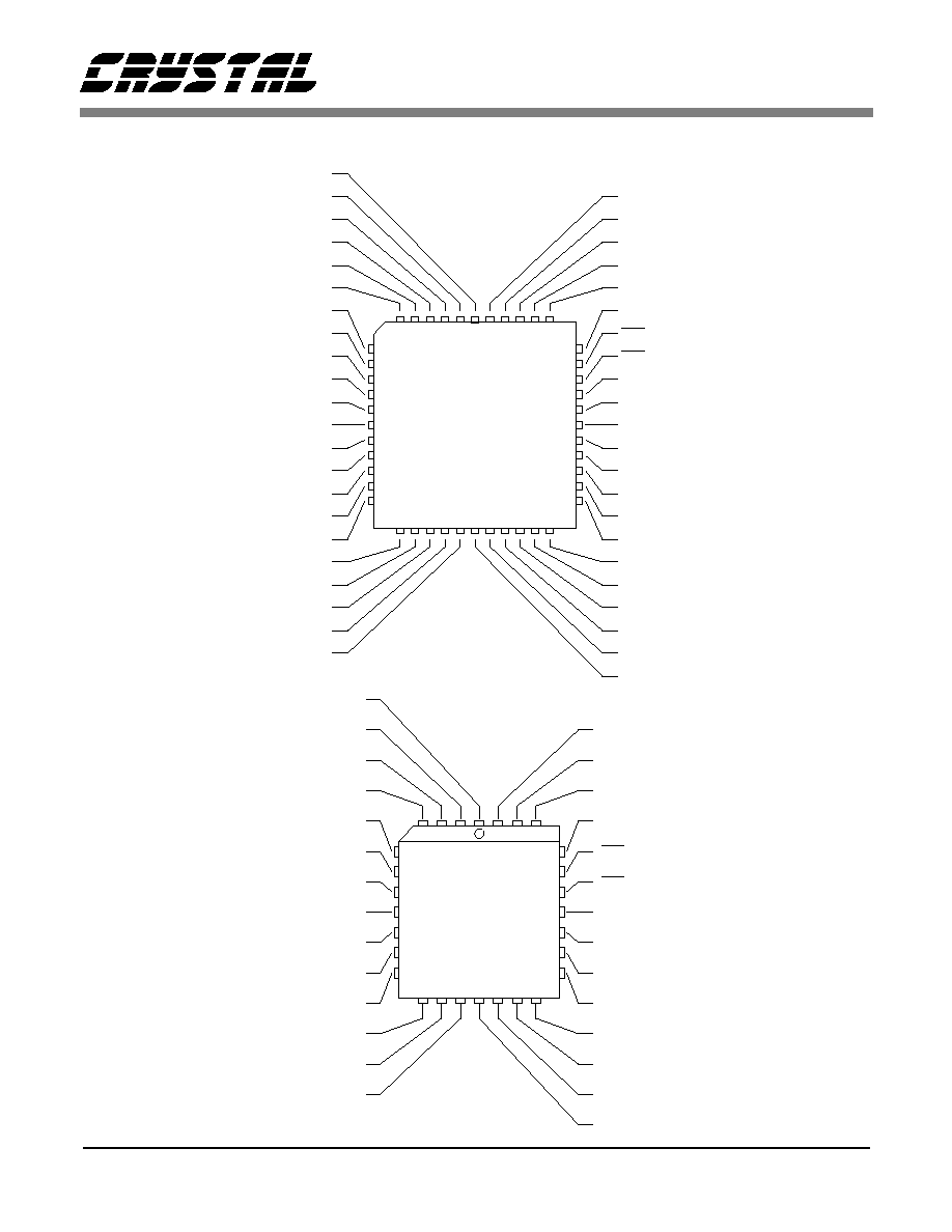
PIN DESCRIPTIONS
40
42
34
36
38
6
2
4
8
10
1
3
5
7
9
11
23
25
27
29
31
33
28
24
26
30
32
44
12
14
16
18
20
22
CS9236
44-pin TQFP
(Q)
MCLK5I
XTAL3I
XTAL0
GND2
VDD2
LRCLK
SOUT
RST
PDN
GND1
VDD1
MIDI_IN
TEST
NC
NC
NC
NC
NC
NC
NC
NC
NC
NC
NC
NC
NC
NC
NC
NC
NC
NC
NC
NC
NC
NC
NC
NC
NC
NC
NC
NC
NC
NC
NC
22
20
24
19
21
23
25
3
27
2
4
26
28
1
12
14
16
18
13
15
17
8
6
10
5
7
9
11
CS9236
28-pin PLCC
(L)
NC
NC
NC
NC
MCLK5I
XTAL3I
XTAL0
GND2
VDD2
LRCLK
SOUT
NC
NC
NC
NC
NC
NC
NC
RST
PDN
GND1
VDD1
NC
NC
NC
NC
MIDI_IN
TEST

CS9236
DS214PP11
31
MIDI_IN - Serial MIDI Data Input, PIN 20 (L), PIN 28 (Q).
Serial MIDI data input to the device. This data stream contains MIDI messages which are used
to control music synthesis and initiation/termination of the Test Tone.
SOUT - Serial Audio Data Output, PIN 11 (L), PIN 8 (Q).
Serial data output stream carrying the stereo digital audio output from the device. The digital
audio output sample rate is 44.1 ksample/s, stereo.
LRCLK - Serial Audio Data Left/Right Clock Output, PIN 10 (L), PIN 7 (Q).
This is the left/right word clock output associated with the serial data output, SOUT. The
LRCLK signal identifies word alignment of the SOUT data stream.
RST - Reset Input, PIN 24 (L), PIN 32 (Q).
This active-low input signal is used to initialize all of the devices internal states and registers to
a known default state. The RST signal will silence the digital audio output.
PDN - Power-Down Input, PIN 23 (L), PIN 31 (Q).
This active-low input signal is used to set the device to the low power consumption Power-
Down mode of operation. The Power-Down mode is fully static; all internal states and register
values are retained during Power-Down. Deassertion of the PDN signal returns the device to
normal operation.
TEST - Factory Test Input, PIN 19 (L), PIN 27 (Q).
Used for factory testing of device. This pin must be tied to digital ground during normal
operation.
MCLK5I - 5 Volt Master Clock Input, PIN 5 (L), PIN 2 (Q).
This is the master clock input for the device. The CS9236 internal timing is derived from one
of two possible sources; the part may be supplied a 16.9344 MHz Master Clock signal from an
external source, or the timing may be generated using the on-chip oscillator circuit in
conjunction with an external 16.9344 MHz quartz crystal. When a Master Clock signal is
provided to the CS9236 from an external device, the Master Clock signal should be connected
to the CS9236 MCLK5I input pin and the XTAL3I input pin is grounded. When the CS9236
internal timing is generated using the on-chip oscillator circuit, a 16.9344 MHz quartz crystal is
connected between the CS9236 XTAL3I input pin and the XTALO output pin, and the
MCLK5I input pin is grounded. In this case, the XTALO output may also be used as a 384X
master clock for the CS9236 digital audio output signal, SOUT.

CS9236
32
DS214PP11
XTAL3I - 3 Volt Crystal Oscillator Input, PIN 6 (L), PIN 3 (Q).
This is the input pin for the on-chip crystal oscillator circuit. The CS9236 internal timing is
derived from one of two possible sources; the part may be supplied a 16.9344 MHz Master
Clock signal from an external source, or the timing may be generated using the on-chip
oscillator circuit in conjunction with an external 16.9344 MHz quartz crystal. When a Master
Clock signal is provided to the CS9236 from an external device, the Master Clock signal
should be connected to the CS9236 MCLK5I input pin and the XTAL3I input pin is grounded.
When the CS9236 internal timing is generated using the on-chip oscillator circuit, a 16.9344
MHz quartz crystal is connected between the CS9236 XTAL3I input pin and the XTALO
output pin, and the MCLK5I input pin is grounded. In this case, the XTALO output may be
used as a 384X master clock for the CS9236 digital audio output signal, SOUT.
XTALO - Crystal Oscillator Output/384X Digital Audio Clock Output, PIN 7 (L), PIN 4 (Q).
This pin is the output of the on-chip crystal oscillator circuit. This output may also be used as a
384X master clock for the CS9236 digital audio output signal, SOUT. The CS9236 internal
timing is derived from one of two possible sources; the part may be supplied a 16.9344 MHz
Master Clock signal from an external source, or the timing may be generated using the on-chip
oscillator circuit in conjunction with an external 16.9344 MHz quartz crystal. When a Master
Clock signal is provided to the CS9236 from an external device, the Master Clock signal
should be connected to the CS9236 MCLK5I input pin and the XTAL3I input pin is grounded.
When the CS9236 internal timing is generated using the on-chip oscillator circuit, a 16.9344
MHz quartz crystal is connected between the CS9236 XTAL3I input pin and the XTALO
output pin, and the MCLK5I input pin is grounded. In this case, the XTALO output may be
used as a 384X master clock for the CS9236 digital audio output signal, SOUT.
VDD1, VDD2 - Digital Supply Voltage, PINS 21 and 9 (L), PINS 29 and 6 (Q), respectively.
3.3VDC supply voltage connections for the device.
GND1, GND2 - Digital Ground, PINS 22 and 8 (L), PINS 30 and 5 (Q), respectively.
0 VDC digital ground connections for the device.
NC - No Connection, PINS 1-4, 12-18, 25-28 (L), PINS 1, 9-26, 33-44 (Q)
These pins must be left floating (no connection to external circuitry).
CS9236
DS214PP11
33
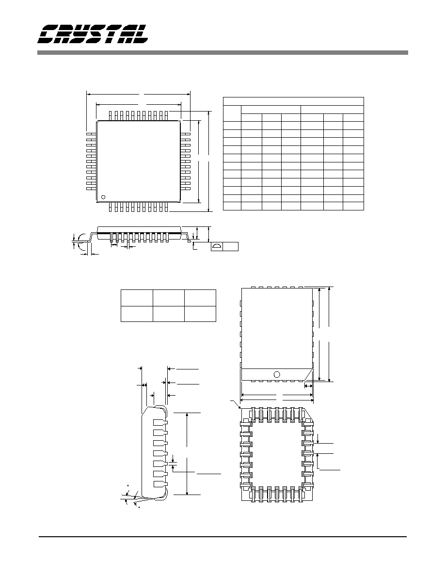
PACKAGE PARAMETERS
e
MILLIMETERS
INCHES
DIM
D/E
D1/E1
e
b
0.462
0∞
0∞
11.75
MIN
MAX
1.45
MIN
MAX
0.057
10.10
12.25
3.5∞
0.398
0.482
b
A1
A
1.60
0.05
0.063
0.002
c
0.20
0.008
c
0.45
0.75
0.018
0.030
1.35
0.053
9.90
0.390
A1
A
44 PIN TQFP
1
D
D1
E1 E
A2
A2
L
L
0.70
0.45
0.026
0.014
0.036
0.90
0.018
0.30
0.09
0.004
NOM
0.15
0.006
NOM
3.5∞
12.0
0.60
1.40
10.0
0.80
0.37
0.145
0.472
0.024
0.055
0.394
0.031
0.016
0.006
ccc
0.10
0.004
7∞
7∞
ccc
44 LEAD TQFP
ALL DIMENSIONS ARE IN MILLIMETERS AND PARENTHETICALLY IN INCHES.
0.25 (0.010) R
MAX
1.35 (0.053)
1.19 (0.047)
A
B
B
A
1.14 (0.045) x 45deg.
NOM
MIN
MAX
MIN
MAX
MIN
MAX
A
B
C
12.32
(0.485)
12.57
(0.495)
11.43
11.58
(0.450) (0.456 )
9.91
10.92
(0.390) (0.430)
3 NOM
0.46 ( 0.018 )
0.33 ( 0.013 )
C
3 NOM
4.62 (0.182)
4.11 (0.162)
1.14 (0.045)
0.63 (0.025)
2.41 (0.095)
28 pin
PLCC
1.27(0.050)
MIN
x45deg.NOM

Smart
Analog
TM
is a Trademark of Crystal Semiconductor Corporation