www.clare.com
DS-ITC107P-R1.2
1
ITC107P
Integrated Telecom Circuits
ITC107P
Units
Hook Switch Breakdown Voltage
350
V
Bridge Rectifier Reverse
Voltage
350
V
Part #
Description
ITC107P
16 Pin SOIC (50/Tube)
ITC107PTR
16 Pin SOIC (1000/Reel)
Applications
Features
Description
Approvals
Ordering Information
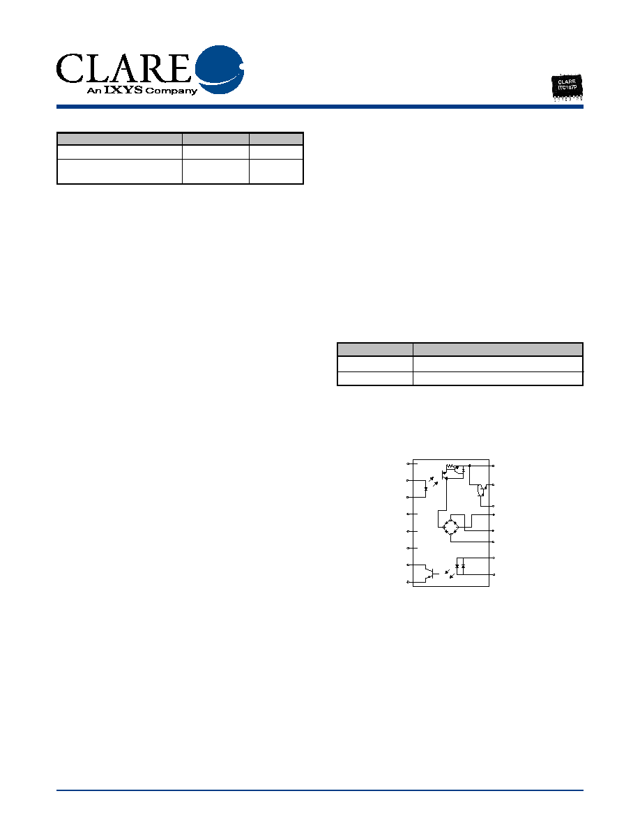
Pin Configuration
The Integrated Telecom Circuit combines a high
voltage optically isolated photodarlington, bridge
rectifier, Darlington transistor and optocoupler into one
16 pin SOIC package, consolidating designs and
reducing component count in telecom applications.
The ITC107's optocoupler provides for full wave
detection of ring signals.
�
Data/Fax Modem
�
Voice Mail Systems
�
Telephone Sets
�
Computer Telephony Integration
�
Set Top Box Modems
�
UL Recognized
�
Complies with EN 60950
�
Small 16 Pin SOIC Package (PCMCIA Compatible)
�
Board Space and Cost Savings
�
No Moving Parts
�
3750V
RMS
Input/Output Isolation
�
FCC Compatible Part 68
�
Photodarlington Hook Switch
�
Full-Wave Bridge Rectifier
�
Darlington Transistor for Electronic Inductor "Dry"
Circuits
�
Full Wave Current Detector for Ring Signal or Loop
Current Detect
�
JEDEC Standard Pin Out
1
2
3
4
5
6
7
8
16
15
14
13
12
11
10
9
NC
NC
NC
NC
Photodarlington LED
Anode
Photodarlington LED
Cathode
Collector -Phototransistor
Emitter -Phototransistor
Photodarlington Emitter
Darlington Emitter
Darlington Base
Bridge Output (-)
Bridge Input
Bridge Input
Phototransistor LED
Phototansistor LED

www.clare.com
2
ITC107P
Rev. 1.2
Absolute Maximum Ratings are stress ratings. Stresses in
excess of these ratings can cause permanent damage to
the device. Functional operation of the device at conditions
beyond those indicated in the operational sections of this
data sheet is not implied.
Parameter
Condition
Symbol
Min
Typ
Max
Units
Photodarlington Portion
Collector-Emitter Breakdown voltage
I
C
= 100uA
B
VCEO
350
-
-
V
Collector Dark Current
V
CE
= 200V
I
CEO
-
-
100
nA
Collector Emitter Saturation Voltage
I
C
= 100mA
V
CE(S)
-
-
1.2
V
I
B
= 150uA
Current Gain
Hfe
I
C
= 40mA V
CE
=2V
2500
-
40000
-
LED Input control Current
-
I
F
5
-
50
mA
LED input Voltage Drop
I
F
= 5mA
V
F
0.9
1.2
1.4
V
LED Reverse Input Voltage
-
V
R
-
-
5
V
LED Reverse Input Current
I
R
= 5V
I
R
-
-
10
mA
Phototransistor Portion
Phototransitor Blocking Voltage
I
C
= 10uA
B
VCEO
20
50
-
V
Phototransistor Dark Current
V
CC
= 5V
I
CEO
-
50
500
mA
I
F
= 0mA
Saturation Voltage
I
C
= 2mA
V
SAT
-
0.3
0.5
V
I
F
= 16mA
Current Transfer Ratio
V
CE
= 0.5V
CTR
33
400
-
%
I
F
= 6mA
LED Input control Current
V
CE
= 0.5V
I
F
6
2
100
mA
I
C
= 2mA
LED input Voltage Drop
I
F
= 5mA
V
F
0.9
1.2
1.4
V
LED Input Current (Detector must be off)
V
CE
= 5V
I
F
5
25
-
uA
I
C
= 10�A
Bridge Rectifier Portion
Reverse Voltage
-
V
RD
-
-
350
V
Forward Voltage Drop
I
FD
= 120mA
V
FD
-
-
1.1
V
Parameter
Min
Typ Max Units
Total Package Dissipation
-
-
1
1
W
Isolation Voltage
Input to Output
3750
-
-
V
RMS
Operational Temperature
-40
-
+85
�C
Storage Temperature
-40
-
+125
�C
Soldering Temperature
-
-
+220
�C
(10 Seconds Max.)
1
Above 25� derate linerity 8.33mw/�C
Total Power Dissipation (PD):
P
D
=P
HOOKSWITCH
+ P
BRIDGE
+ P
DARLINGTON
+ P
LED
P
D
=(R
DS
(on)) (I
2
L
) + 2(V
F
)(I
L
) + (V
CE
)(I
L
) + (V
LED
)(I
F
)
WHERE:
R
DS
(on) = Maximum realy on resistance
I
L
= Maximum loop current
V
F
= Maximum diode forward voltage
V
CE
= Maximum voltage collector to emitter
V
LED
= Maximum LED forward voltage
I
F
= Maximum LED current
Absolute Maximum Ratings (@ 25� C)
Electrical Characteristics

ITC107P
www.clare.com
3
Rev. 1.2
Parameter
Condition
Symbol
Min
Typ
Max
Units
Reverse Leakage Current
V
R
= 350Y
I
RD
-
-
10
uA
T
J
= 25
o
C
T
J
= 85
o
C
50
uA
Forward Current Continuous
I
FD
-
-
140
mA
Forward Current Peak
T= 10mS
I
FD
-
-
0.5
A
Darlington Portion
Collector Emitter Voltage
I
C
=10mA DC
V
CEO
20
-
-
V
I
B
=0
Collector Current Continous
V
C
=3.5V
I
C
-
-
120
mA
Off � State Collector Emitter
V
CE
=10V
I
CEX
-
-
1
uA
Leakage Current
I
B
=0mA
DC Gain Current
V
CE
=5VDC
h
FE
300
-
-
-
I
C
=100mA
Saturation Voltage
I
C
=120mA
V
CE(SAT)
-
-
1.5
V
Total Harmonic Distortion
F
0
=300Hz @
-
-
-
-80
dB
-10dBm
I
C
=40mA
Electrical Characteristics

Clare, Inc. makes no representations or warranties with respect to the accuracy or completeness of the contents of this publication and reserves the right to make changes to specifications and product descriptions
at any time without notice. Neither circuit patent licenses nor indemnity are expressed or implied. Except as set forth in Clare's Standard Terms and Conditions of Sale, Clare, Inc. assumes no liability whatsoever, and
disclaims any express or implied warranty, relating to its products including, but not limited to, the implied warranty of merchantability, fitness for a particular purpose, or infringement of any intellectual property right.
The products described in this document are not designed, intended, authorized or warranted for use as components in systems intended for surgical implant into the body, or in other applications intended to support
or sustain life, or where malfunction of Clare's product may result in direct physical harm, injury, or death to a person or severe property or environmental damage. Clare, Inc. reserves the right to discontinue or make
changes to its products at any time without notice.
Specification: DS-ITC107P-R1.2
�Copyright 2003, Clare, Inc.
OptoMOS
�
is a registered trademark of Clare, Inc.
All rights reserved. Printed in USA.
2/24/03
For additional information please visit our website at: www.clare.com
MECHANICAL DIMENSIONS
1.270 TYP.
(0.050 TYP.)
2.108 MAX.
(0.083 MAX.)
1.981 TYP.
(0.078 TYP.)
1.016 TYP.
(0.040 TYP.)
8.890 TYP.
(0.350 TYP.)
0.406 TYP.
(0.016) TYP.
16 Pin SOIC ("P" Suffix)
0.254 0.0127
(0.010 0.0005)
7.493 0.127
(0.295 0.005)
10.160 0.381
(0.400 0.015)
10.363 0.127
(0.408 0.005)
PC Board Pattern
(Top View)
1.193
(0.047)
0.787
(0.031)
1.270
(0.050)
9.728 0.051
(0.383 0.002)
Tape and Reel Packaging for 16 Pin SOIC Package
Top Cover
Tape
12.00
(0.172)
User Direction of Feed
16.30 MAX.
(0.642 MAX.)
Embossment
Embossed Carrier
Top Cover
Tape Thickness
0.102 MAX.
(0.004 MAX.)
330.2 DIA.
(13.00 DIA.)
1
16
2.70
(0.106)
4.90
(0.193)
10.90
(0.430)
10.70
(0.421)
Dimensions
mm
(inches)