 | –≠–ª–µ–∫—Ç—Ä–æ–Ω–Ω—ã–π –∫–æ–º–ø–æ–Ω–µ–Ω—Ç: TD-8030 | –°–∫–∞—á–∞—Ç—å:  PDF PDF  ZIP ZIP |

MICROWAVE NOISE TUBES & NOISE SOURCES
571
DESCRIPTION
www.cpclare.com
TD/TN Series
SPECIFICATION RANGES
APPLICATIONS
FEATURES
CP Clare's TD Series of gas discharge microwave noise tubes and TN Series of gas discharge microwave noise
sources are the element in a microwave RF system that allows accurate measurements of the noise figure of the
receiver or its components. The requirements of a device used for making such noise figure measurements
include broad bandwidth inherent in the active element, stability, ease of operation, and long life. In general, the
range of usefulness of these noise sources permits measurements of noise figures from about 2 to 30dB. The
PS-237 through PS-240 current-regulated power supplies can be used to operate many of the noise sources
described herein.
s
Excess noise ratios (ENR): up to 20dB
s
Broad bandwidth
s
Excellent long term stability
s
Life up to 20,000 hours
s
AC, DC, or pulsed operation
s
Noise figure measurement
Parameter
Range
Units
Frequency
0.2 - 220.0
GHz
ENR
8.8 - 20.1
dB
Operating Current
30 - 250
mA
Starting Voltage
0.9 - 7.0
kV
(See detailed specifications for more data. Contact CP Clare for TD and TN part numbers or for other
requirements not listed.)

MICROWAVE NOISE TUBES & NOISE SOURCES
572
North America: 1-800-CPCLARE
Europe: 32-11-300868
Asia: 886-2-2523-6368
Japan: 81-3-3980-2212
TD/TN Series
All characteristics at 25∞C.
FREQUENCY
BAND
WAVE-
PART # /
PACKAGE
MOUNT
RECOMMENDED
MINIMUM
DC ANODE
TUBE DROP
TUBE-IN
RANGE
GUIDE
EIA TYPE
OUTLINE
TYPE
MODE OF
STARTING
STARTING
(VDC)
MOUNT
(GHz)
NUMBER
OPERATION
(1)
VOLTAGE SPIKE
CURRENT
ENR
(kV)
(mA)
(dB)
1.12-1.70
L
WR-650
TD-21/6881
1
90
∞
H
DC
4.0
250
65
15.20
(2)
TD-29/7101
1a
90
∞
H
AC,DC
4.5
250
130
18.00
(2)
(1.20-1.40 only)
TD-33/7147
1a
90
∞
H
AC,DC
4.0
250
75
15.20
(2)
TD-49
1
90
∞
H
pulse
4.0
200
125
15.20
(2)
TD-62/7992
1
90
∞
H
DC
4.5
250
~145
18.00
(2)
TD-75
1
90
∞
H
pulse
4.5
200
235
18.00
(2)
TD-91
special
10
∞
E
DC
7.0
250
230
15.20
(2)
2.60-3.95
S
WR-284
TD-12/6358
2
10
∞
E
DC
2.7
250
80
15.20
TD-22/6782
special
90
∞
H
AC,DC
2.0
250
45
8.85
TD-31
2a
10
∞
E
AC,DC
2.7
250
90
15.20
TD-32
2a
10
∞
E
AC,DC
2.7
250
170
17.80
TD-34/7148
2
10
∞
E
DC
2.7
250
160
17.75
TD-38/8151
2
10
∞
E
pulse
3.3
200
145
15.27
TD-56/8286
2
10
∞
E
pulse
3.5
200
265
17.90
TD-82
special
90
∞
E
DC
0.9
75
55
18
3.30-4.90
S
WR-229
TD-24
special
10
∞
E
AC,DC
2.5
250
60
15.30
TD-30
special
10
∞
E
AC,DC
2.5
250
110
1
3.95-5.85
C(G)
WR-187
TD-10/6356
3
10
∞
E
DC
3.1
250
70
15.32
TD-39/7999
3
10
∞
E
pulse
3.5
175
140
15.50
TD-43/8287
3
10
∞
E
pulse
3.5
175
210
17.85
TD-48/7989
3
10
∞
E
DC
2.7
250
135
17.70
TD-83
special
90
∞
E
DC
0.9
100
55
18.90
5.85-8.20
X(J)
WR-137
TD-10/6356
3
10
∞
E
DC
3.1
250
75
15.65
TD-39/7999
3
10
∞
E
pulse
3.5
175
140
15.50
TD-43/8287
3
10
∞
E
pulse
3.5
175
210
17.90
TD-48/7989
3
10
∞
E
DC
2.7
250
135
17.75
TD-67/8288
3
15
∞
E
pulse
3.5
150
225
18.00
8.20-12.40
X
WR-90
TD-11/6357
4
10
∞
E
DC
2.7
200
75
15.60
TD-23/6882
4
10
∞
E
DC
2.7
200
115
18.00
TD-40/8152
4
10
∞
E
pulse
3.3
175
125
15.60
TD-44/7988
4
10
∞
E
pulse
3.5
175
205
18.00
TD-58/8293
4
10
∞
E
pulse
3.5
175
208
17.75
TD-72/8059
4
10
∞
E
pulse
3.3
175
133
15.56
TD-73
special
90
∞
E
DC
0.9
100
54
14.50
TD-93B
special
90
∞
E
pulse
0.9
100
165
14.50
TD-114
special
10
∞
E
DC
1.5
200
90
15.30
12.40-18.00
Ku
WR-62
TD-18/6684
5
10
∞
E
DC
2.7
200
70
15.80
TD-41/8030
5
10
∞
E
pulse
3.3
175
130
15.85
TD-46
special
20
∞
E
AC,DC
~1.2
100
35
15.20
(2)
TD-54/7991
5
10
∞
E
DC
2.7
200
130
18.00
TD-55/8290
5
10
∞
E
pulse
3.5
175
230
17.85
TD-92
5
10
∞
E
pulse
3.5
175
125
15.65
18.00-26.50
K
WR-42
TD-13/6359
6
10
∞
E
pulse
2.7
200
68
15.90
TD-42/8031
6
10
∞
E
DC
3.3
175
125
16.00
TD-50/7990
6
10
∞
E
pulse
2.7
200
157
18.05
TD-51/8291
6
10
∞
E
DC
3.5
175
260
17.90
TD-81
special
10
∞
E
DC
3.3
150
148
16.15
26.50-40.00
Ka
WR-28
TD-76/7993
special
10
∞
E
DC
2.7
125
130
16.0
TD-77/8292
special
10
∞
E
pulse
3.0
100
175
16.0
(1)
DC operation -- cathode at one end only.
AC,DC operation -- cathodes at both ends.
Pulse operation -- cathode at one end specially designed for pulse operation. If the anode current during the "on" time of a square wave pulse (>100
µ
s duration) is nominally the
same as the rated DC anode current, the tube drop during this period will be approximately the same as the rated DC tube drop.
(2)
Excess noise ratio of tube only.
TD SERIES GAS DISCHARGE NOISE SOURCE TUBES
with Filamentary or Hollow Cathodes
MICROWAVE NOISE TUBES & NOISE SOURCES
573
www.cpclare.com
TD/TN Series
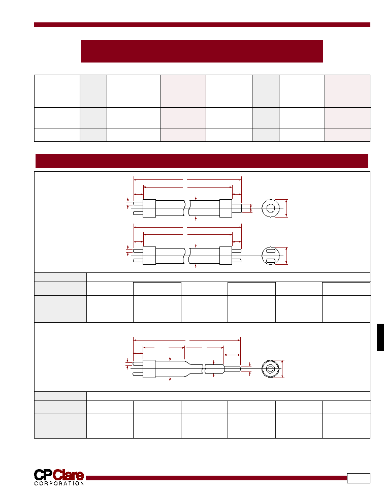
OUTLINE DRAWINGS (Noise Source Tubes with Filamentary or Hollow Cathodes)
TD SERIES GAS DISCHARGE NOISE SOURCE TUBES
with Indirectly-Heated Cathodes
All characteristics at 25∞C.
FREQUENCY
BAND
PART NUMBER/
MINIMUM
DC ANODE
TUBE
TUBE-IN-
USED IN
RANGE
EIA TYPE
STARTING
CURRENT
DROP
MOUNT
MOUNT
(GHZ)
NUMBER
VOLTAGE
(mA)
(VDC)
ENR
SPIKE (kV)
(dB)
3.4-3.6
S
TD-124
0.60
75
40
18.30
TN-65
2.9-3.1
TD-129
0.45
75
35
18.50
TN-71
2.7-2.9
TD-121
0.45
75
35
18.50
TN-72
8.2-12.4
X
TD-126
1.50
100
90
15.6
TN-130
F
A
E
B
C
0.74
±
0.08
(0.292
±
0.032)
0.24 TYP.
(0.097)
D
D
A
E
B
ALT. - A
C
0.74
±
0.08
(0.292
±
0.032)
0.24 TYP.
(0.097)
DIMENSION (INCHES)
OUTLINE NUMBER
A
B
C
D
E
F
1/1a
(3)
various
0.500 max
14.625-15.000
1.350-1.435
1.475-1.550
0.188 max
2/2a
(3)
16.937-17.437
0.310-0.360
17.625-18.000
0.990 max
0.975-1.050
0.305-0.325
3/3a
(3)
13.875-14.375
0.270-0.320
14.375-15.000
0.555 max
0.547-0.579
0.245-0.265
A
D
1.27 MAX.
(0.500)
0.48 MAX. DIA.
(0.188)
C
0.74
±
0.08
(0.292
±
0.032)
6.98 MAX.
(2.750)
0.24 TYP.
(0.097)
1.41 DIA. MAX.
(0.555)
E
DIMENSION (INCHES)
OUTLINE NUMBER
A
B
C
D
E
F
4
8.625 min
1.500 max
11.937-12.250
0.370-0.380
0.550 max
0.3804
5
7.375 min
1.250 max
10.875-11.250
0.235-0.265
0.500 max
0.2654
6
6.187 min
1.250 max
9.687-10.000
0.160-0.194
0.500 max
0.1944
(3)
The "a" suffix indicates using the bi-pin termination depicted in the inset labelled "ALT.-A".
(4)
The diameter of the tube shall not exceed this value over the length of the tube denoted in the figure by "B".

MICROWAVE NOISE TUBES & NOISE SOURCES
574
North America: 1-800-CPCLARE
Europe: 32-11-300868
Asia: 886-2-2523-6368
Japan: 81-3-3980-2212
TD/TN Series
TD SERIES GAS DISCHARGE NOISE SOURCE TUBES
with Indirectly-Heated Cathodes
(5)
All characteristics at 25∞C.
BAND
PART
FREQUENCY
ENR
TUBE
DC ANODE
MINIMUM
CIRCUIT
MOUNTING
CIRCUIT
NUMBER
RANGE
(dB)
DROP
CURRENT
STARTING
LENGTH
(GHz)
(VDC)
(mA)
VOLTAGE
(INCHES)
SPIKE (kV)
VHF
TN-46
0.2-0.25
18.5
200
30
1.5
15.50
Helical Coupling
7/8" coax
UHF
TN-47
0.56-0.64
20.3
325
50
2.0
16.5
Direct Coupling
7/8" coax
TN-48
0.34-0.51
18.5
75
2.0
10.0
Helical Coupling
Type N
L
TN-51
1.0-2.0
20.1
200
50
1.9
8.94
Direct Coupling
7/8" coax
TN-52
1.0-2.0
20.1
200
50
1.9
10.38
Direct Coupling
7/8" coax
TN-54
1.0-2.0
20.5
200
50
1.9
17.31
Direct Coupling
Type N
TN-55
1.25-1.55
20.1
200
50
1.9
9.56
Direct Coupling
7/8" coax
TN-57
1.28-1.35
20.5
225
50
1.9
12.56
Direct Coupling
7/8" coax
S
TN-60
2.0-4.0
18.5
200
50
1.9
10.38
Direct Coupling
7/8" coax
TN-64
2.7-2.9
18.5
35
60
0.45
3.75
90
∞
E
RG-75/U
TN-65
3.4-3.6
18.3
40
75
0.6
2.50
90
∞
E
RG-75/U
TN-71
2.9-3.1
18.5
35
75
0.45
3.63
90
∞
E
RG-75/U
TN-72
2.7-2.9
18.5
35
75
0.45
3.09
90
∞
E
RG-75/U
TN-73
2.7-2.9
18.5
35
75
0.45
3.09
90
∞
E
RG-75/U
TN-74
2.7-2.9
18.5
35
60
0.45
3.75
90
∞
E
RG-75/U
TN-75
3.1-3.5
18.3
40
75
0.6
2.63
90
∞
E
RG-75/U
C
TN-76
5.3-6.0
18.5
60
150
0.7
2.00
90
∞
E
RG-49/U
TN-77
5.3-6.0
13.5
60
150
0.7
3.50
90
∞
E
RG-49/U
TN-78
5.45-5.82
18.5
60
150
0.7
2.75
90
∞
E
RG-95/U
TN-82
5.3-6.0
13.5
60
150
0.7
3.56
90
∞
E
RG-49/U
H
TN-83
7.5-8.6
18.5
60
75
0.8
1.56
90
∞
E
RG-51/U
TN-84
7.5-8.6
15.0
55
100
0.8
2.50
90
∞
E
RG-51/U
X
TN-94
8.9-9.1
18.5
50
60
0.95
1.63
90
∞
E
RG-67/U
TN-95
8.5-9.6
14.5
50
100
0.95
2.50
90
∞
E
RG-67/U
TN-97
8.5-9.6
18.5
50
75
0.95
1.63
90
∞
E
RG-67/U
TN-101
8.5-9.6
14.5
50
100
0.95
2.25
90
∞
E
RG-52/U
TN-124
8.2-12.4
12.5
50
50
1.00
2.50
90
∞
E
RG-52/U
Ku(K)
TN-102
15.0-16.5
18.5
60
40
1.2
1.50
90
∞
E
RG-67/U
TN-103
12.4-18.0
18.5
140
50
2.0
7.50
0
∞
E
RG-107/U
TN-104
15.0-16.6
12.3
95
50
1.0
1.63
90
∞
E
RG-91/U
TN-128
12.0-14.0
13.5
50
50
1.0
2.00
90
∞
E
RG-91/U
K(P)
TN-106
18.0-26.5
18.5
175
50
1.9
6.44
0
∞
E
RG-66/U
TN-125
22.0-23.0
12.5
65
50
1.5
2.25
90
∞
E
RG-53/U
Ka(Q)
TN-107
26.5-40.0
18.0
140
40
2.5
5.13
0
∞
E
RG-96/U
TN-109
34.0-36.0
18.0
140
35
2.5
7.38
0
∞
E
RG-96/U
TN-126
31.0-32.0
13.3
75
50
1.5
2.25
90
∞
E
RG-96/U
R
TN-111
50.0-75.0
18.0
230
30
2.5
4.63
0
∞
E
RG-98/U
(5)
CP Clare can usually refurbish noise sources (depending on condition of waveguide) and install replacement tubes.
MICROWAVE NOISE TUBES & NOISE SOURCES
575
www.cpclare.com
TD/TN Series
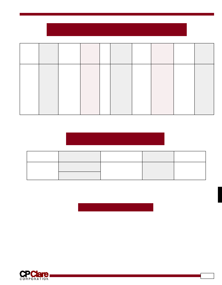
ORDERING INFORMATION
TD SERIES GAS DISCHARGE NOISE SOURCE TUBES
with Filamentary Cathode Noise Tubes
(5)
NOISE SOURCE POWER SUPPLIES
with Current Regulation
All characteristics at 25∞C
WAVE-GUIDE
PART
FREQUENCY
APPROX.
TUBE
DC ANODE
MINIMUM
REPLACEMENT
MOUNTING
FLANGE
NUMBER
RANGE
ENR
DROP
CURRENT
STARTING
TUBE
MATE
(GHz)
(dB)
(VDC)
(mA)
VOLTAGE
SPIKE (kV)
WR-42
TN-170
18.0-26.5
15.0
170
120
2.0
TD-170
7
∞
E
UG-595/U
WR-28
TN-162
26.5-40.0
15.4
170
120
2.0
TD-162
7
∞
E
UG-599/U
WR-22
TN-172
33.0-50.0
15.4
170
120
2.0
TD-172
7
∞
E
UG-599/U
WR-19
TN-163
40.0-60.0
15.4
170
120
2.0
TD-163
7
∞
E
UG-385/U
WR-15
TN-164
50.0-75.0
15.0
170
120
2.0
TD-164
7
∞
E
UG-385/U
WR-12
TN-171
60.0-90.0
15.0
210
100
2.5
TD-171
7
∞
E
UG-385/U
WR-10
TN-165
75.0-110.0
14.2
225
75
3.0
TD-165
7
∞
E
UG-385/U
WR-8
TN-167
90.0-140.0
13.0
225
75
3.0
TD-167
7
∞
E
UG-385/U
WR-6
TN-166A
110.0-170.0
13.0
225
50
3.0
TD-166A
7
∞
E
UG-385/U
WR-5
TN-173
140.0-220.0
9.0
225
50
3.0
TD-173
7
∞
E
UG-385/U
(5)
CP Clare can usually refurbish noise sources (depending on condition of waveguide) and install replacement tubes.
A complete part number is represented by
the information in the Part Number column
of the specification table.
PART NUMBER
FOR NOISE TUBES
(6)
AC INPUT
DC STARTING
DC OPERATING
VOLTAGE (kV)
CURRENT (mA)
PS-237
TN-162 thru TN-172
115VAC, 60Hz
5.0
150
PS-238
except TN-166A
220VAC, 50Hz
5.0
150
PS-239
TN-173, TN-166A
115VAC, 60Hz
5.0
120
PS-240
220VAC, 50Hz
5.0
75
(6)
These power supplies, though designed for the TN-162 through TN-173, are capable of operating many other noise sources made by CP Clare.