Reverse Voltage: 50 - 1000 Volts
Forward Current: 4.0 Amp
KBL400 Thru KBL410
Features
- Diffused Junction
- Low Forward Voltage Drop
- High Reliability
- High Current Capability
-
- Ideal for Printed Circuit Boards
- Case: Molded Plastic
- Terminals: Plated Leads Solderable per MIL
STD-202, Method 208
- Weight: 5.6 grams (approx.)
- Mounting Position: Any
High Surge Current Capability
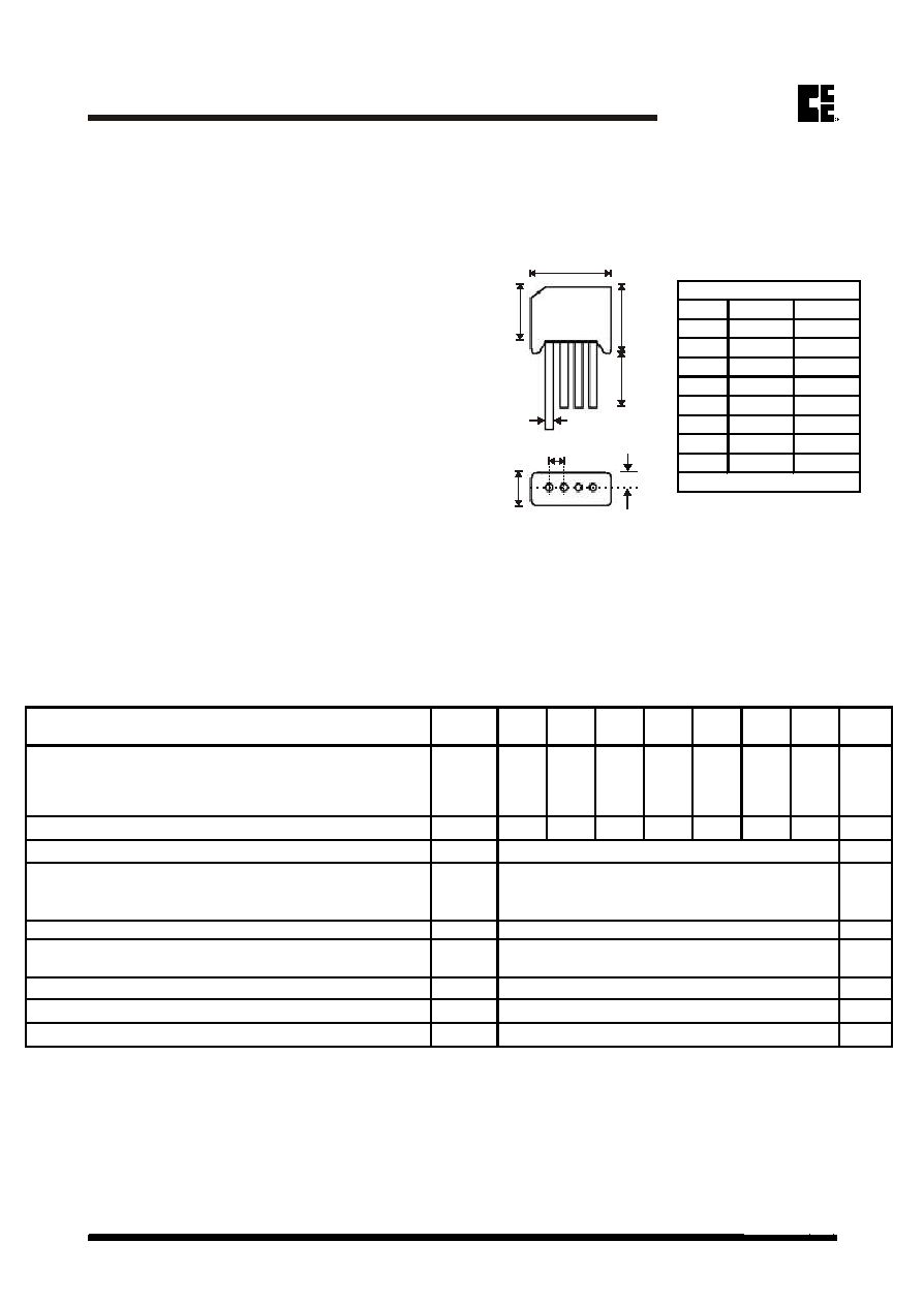
Mechanical Data
Silicon Bridge Rectifiers
Silicon Bridge Rectifiers
www.comchiptech.com
COMCHIP
COMCHIP
MDS0312010A
Page 1
KBL
KBL
~
~
G
G
+
+
-
-
~
~
~
~
A
A
B
B
C
C
H
H
J
J
E
E
D
D
Peak Repetitive Reverse Voltage
V
RRM
Working Peak Rever
se Voltage
V
RWM
DC Blocking Voltage
V
R
RMS Reverse Voltage
V
R(RMS)
35
70
140
280
420
560
700
V
Average Rectified Output Current (Note1) @ T
A
= 75�C I
O
A
Non-Repetitive Peak Forward Surge Current 8.3ms Single
half sine-wave superimposed on rated load (JEDEC
Method)
I
FSM
A
Forward Voltage (per element) @I
F
= 2.0A
V
FM
V
Peak Reverse Current @T
C
= 25�C
uA
At Rated DC Blocking Voltage @T
C
= 100�C
mA
I
2
t Rating for Fusing (t < 8.3ms) (Note1)
I
2
t
A
2
s
Typical Thermal Resistance (Note2)
R
JC
K/W
Operating and Storage Temperature Range
T
j
, T
STG
�C
Maximum Ratings and Electrical Characterics
Rating at 25�C unless otherwise specified.
CHARACTERISTICS
Single Phase, half wave, 60Hz, resistive or inductive load.
For capacitive load, derate current by 20%.
Symbol
KBL
410
UNIT
150
KBL
406
KBL
408
50
KBL
400
KBL
401
KBL
402
KBL
404
I
R
100
200
400
10
1.1
V
1.0
800
1000
4
600
166
19
Note: 1. Non-repetitive for t > 1ms and < 8.3ms.
2. Thermal resistance junction to am
bient mounted on PC board with 13.0 x 13.0 x 0.03mm thick land areas.
-65 to +125
Dim
M i n
M a x
A
18.50
19.50
B
13.70
14.70
C
15.20
16.30
D
6.00
6.50
E
4.60
5.60
G
-
2.10
H
19.00
-
J
1.20
1.30
KBL
All Dimensions in mm

MDS0312010A
Page 2
COMCHIP
COMCHIP
www.comchiptech.com
Silicon Bridge Rectifiers
Silicon Bridge Rectifiers
Rating and Characteristic Curves (KBL400 thru 410)
250
250
150
150
100
100
50
50
0
0
200
200
1.0
1.0
10
10
100
100
Number of Cycles at 60Hz
I
FSM,
Peak
Forward
Surge
Current
(
A
)
8.3ms
Single half sine-wave
JEDEC method
8.3ms
Single half sine-wave
JEDEC method
FIG.4- TYPICAL REVERSE CHARACTERISTICS
PER BRIDGE ELEMENT
INST
ANT
ANEOUS
REVERSE
CURRENT
.(
A
)
0
20
40
60
80
100
120
140
.01
0.1
1.0
10.0
PERCENT OF RATED PEAK REVERSE VOLTAGE. (%)
TJ=100 C
0
TJ=25 C
0
FIG.2- MAXIMUM FORWARD CURRENT DERATING
CURVE
A
VERAGE
FOR
W
ARD
CURRENT
.
(A)
0
50
100
150
0
1
3
2
4
5
AMBIENT TEMPERATURE. ( C)
o
FIG.3- TYPICAL INSTANTANEOUS FORWARD
CHARACTERISTICS PER BRIDGE ELEMENT
INST
ANT
ANEOUS
FOR
W
ARD
CURRENT
.
(A)
.4
.6
.8
1.0
1.2
1.4
1.6
0.01
0.1
1.0
10
INSTANTANEOUS FORWARD VOLTAGE. (V)
Tj=25 C
PULSE WIDTH-300 S
2% DUTY CYCLE
0
FIG.1- MAXIMUM NON-REPETITIVE PEAK Fwd SURGE CURRENT