Data Sheet (Preliminary)
Conexant Proprietary Information
Doc. No.100394B
October 19, 1999
AccessRunner
ADSL Modem Device Set for PCI Applications
Controller-less, Scalable, Discrete Multitone-based, G.dmt- and G.lite-
compliant, ADSL Modem Device Set for PCI Applications
Conexant's AccessRunner
ADSL modem device set is compliant
with the full-rate ANSI T1.413 Issue 2 and ITU G.dmt (G.992.1)
ADSL standards, and with the splitterless ITU G.lite (G.992.2)
specification. This rate-adaptive solution is designed for controller-
less PCI desktop applications and supports downstream data rates
of up to 8 Mbps and upstream data rates of up to 1 Mbps.
The device set takes advantage of the processing power available
with most new computers by eliminating the need for a separate
microcontroller, resulting in a cost-effective solution suitable for
both G.dmt and G.lite applications. Host-based software provides
support for current industry standards for PPP over AAL5 over
ATM over ADSL and RFC 1483 for Windows 98 and Windows
2000.
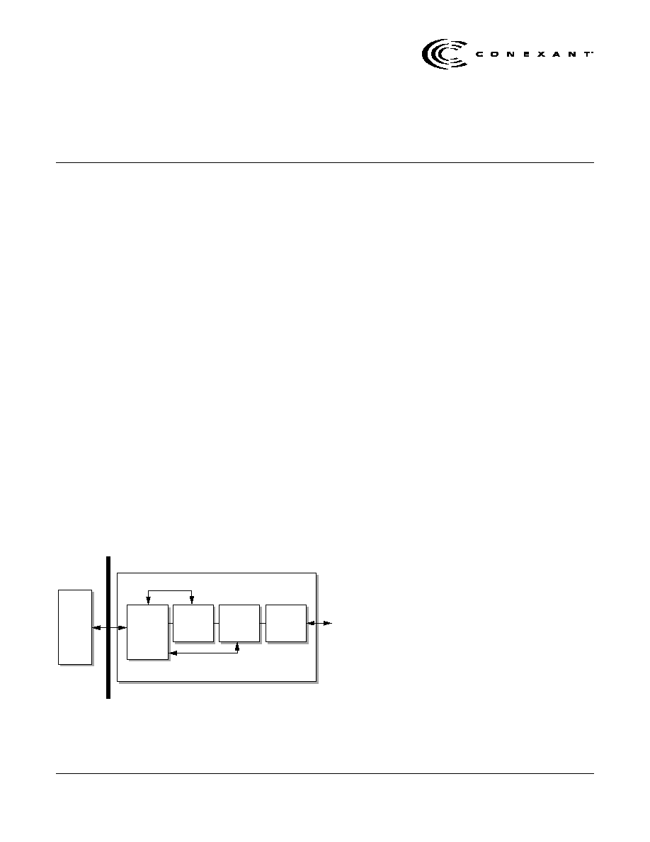
The device set, as shown in Figure 1, consists of four chips:
�
PCI bus interface (AccessRunner P46 in a 176-pin TQFP)
�
DMT-based data pump (AccessRunner 11627 in a 176-pin
TQFP)
�
Analog front end (AccessRunner 20431 in a 32-pin TQFP)
�
Line driver (AccessRunner 20441 in a 16-pin SSOP or
32-pin TQFP)
PCI Bus
Host-
Based
ADSL
Controller
Software
P46
PCI Bus
Interface
176-pin TQFP
11627
ADSL DMT
Data Pump
176-pin TQFP
20431
Analog Front
End
32-pin TQFP
20441
Line Driver
16-pin TSSOP
Telephone
Line
Figure 1. AccessRunner ADSL Modem for PCI Applications
Features
�
Complete controller-less PCI ADSL
solution
�
Compliant with ADSL standards
-
Full-rate ANSI T1.413 Issue 2 and ITU
G.dmt (G.992.1) standards
-
Splitterless ITU G.lite (G.992.2)
specification
�
DMT modulation and demodulation
�
Full-rate adaptive modem
-
Maximum downstream rate of 8 Mbps
-
Maximum upstream rate of 1 Mbps
�
Supports splitterless ADSL
implementation
�
WAN mode support: PPP over AAL5/ATM
over ADSL via Windows 98/2000
�
LAN mode support: RFC 1483 via
Windows 98/2000
�
Compliant with PCI Local Bus
Specification, Revision 2.2
�
Compliant with PCI Bus Power
Management Interface Specification,
Version 1.0
�
Tone detection for low power mode
D20431 AFE Features
�
Receive signal path includes:
-
Integrated hybrid receiver circuit with
programmable gain
-
High pass filtering and 27dB of
Automatic Gain Control (AGC) to
improve signal-to-echo ratio
-
14-bit ADC
�
Transmit signal path includes:
-
30dB of AGC for transmit power control
-
Low pass filtering to suppress noise in
the receive band
-
14-bit DAC
�
Independent digital serial data and control
interfaces
�
Low power tone detection mode.

AccessRunner
Controller-less ADSL Modem Device Set for PCI Applications
2
Conexant
Doc. No. 100394B
Proprietary Information
October 19, 1999
ADSL (Asymmetric Digital Subscriber Line) is a transmission
technology used to carry user data over a single twisted pair line
from the Central Office to the customer premises. The downstream
(Central Office to Customer Premises) direction typically supports
a much higher data rate than the upstream or return (Customer
Premises to Central Office) channel. This asymmetric nature lends
itself to applications like remote LAN access, Internet access, and
video delivery. The downstream data rates can go up to 8 Mbps.
The upstream data rates can go up to 1 Mbps. Actual data rates
depend on the transceiver implementation, loop length,
impairments, and transmitted power.
The Conexant ADSL Modem Device Set for PCI Applications is
based upon a scalable architecture. This architecture will enable
the device set to support an emerging set of ADSL specifications
called G.lite. G.lite is expected to make it possible for telcos to
deploy consumer-oriented, "always on" 1.5 Mbps Internet access
services without the need for splitter equipment or wiring changes
at the customer premises.
D20441 Line Driver Features
�
Differential input and output line driver
�
Thermal shutdown capability
�
Line impedance matching during power-
down
�
Fixed differential gain
11627 ADSL DMT Data Pump
Features
�
Low power (0.5W) consumption
�
DSP-based programmable ADSL data
pump
�
No external Interleave RAM, 16 Kbytes
built-in
�
Single 3.3V
�
5% power supply
�
Echo cancellation
�
Digital interface and rate buffering
�
ADSL framing
�
Forward Error Correction (FEC) encoding
and decoding and interleaving
�
Constellation encoding/decoding
�
IFFT modulation and FFT demodulation
�
Transmit and receive signal digital filtering
�
Time domain equalization
�
Frequency domain equalization
�
Clock recovery
�
CRC and scrambling
�
Digital interface framing
�
ATM mode
�
Bit-synchronous mode
Ordering Information
Product
Package
Device Number
AccessRunner P46 PCI Bus Interface
176-pin TQFP
P46
AccessRunner 11627 ADSL Discrete Multitone (DMT) Data Pump
176-pin TQFP
11627
AccessRunner 20431 Analog Front End
32-pin TQFP
20431
16-pin SSOP
20441-12
AccessRunner 20441 Line Driver
32-pin TQFP
20441-11
Revision History
Revision
Date
Comments
A
07/09/99
Initial release
B
10/19/99
Defined dash numbers and updated figures for 20441 line driver, changed document number from DSL-
015, A
Information provided by Conexant Systems, Inc. is believed to be accurate and reliable. However, no responsibility is assumed by Conexant for its use, nor any
infringement of patents or other rights of third parties which may result from its use. No license is granted by implication or otherwise under any patent rights of
Conexant other than for circuitry embodied in Conexant products. Conexant reserves the right to change circuitry at any time without notice. This document is
subject to change without notice.
Conexant products are not designed or intended for use in life support appliances, devices, or systems where malfunction of a Conexant product can reasonably be
expected to result in personal injury or death. Conexant customers using or selling Conexant products for use in such applications do so at their own risk and agree
to fully indemnify Conexant for any damages resulting from such improper use or sale.
Conexant, "What's Next in Communications Technologies", AccessRunner, LANfinity, and the Conexant logo, are trademarks of
Conexant Systems, Inc.
Product names or services listed in this publication are for identification purposes only, and may be trademarks or registered trademarks of their respective
companies. All other marks mentioned herein are the property of their respective owners.
�1999, Conexant Systems, Inc.
All Rights Reserved
Controller-less ADSL Modem Device Set for PCI Applications
AccessRunner
Doc. No. 100394B
Conexant
3
October 19, 1999
Proprietary Information
Detailed Description
P46 PCI Bus Interface
The P46 PCI bus interface is the bridge device
between the 11627 ADSL DMT data pump and the
host computer. It provides the control, interface, and
data manipulation for the 11627 data pump, the
20431 AFE, the 20441 line driver, and hybrid
circuitry. It is compliant with the PCI Local Bus
Specification, Revision 2.2 and PCI Bus Power
Management Interface Specification, Version 1.0.
20431 Analog Front End
The 20431 AFE is designed for use in full-rate and
G.lite (G.992.2) ADSL modems. The ADSL AFE
interfaces with the transmit line driver (20441) and
the hybrid receive circuitry on the analog side, and
with the ADSL DMT data pump (11627) on the digital
side. The receive section filters out the unwanted
echo and boosts the wanted signal before
performing an A/D conversion. The transmit section
converts digital data to analog signals and performs
a smoothing operation before presenting the signals
to the line driver.
The 20431 is designed to operate from a 3.3V supply
(nominal), assuming that it is regulated within
�
5%. The
maximum allowable supply voltage is 3.6V.
11627 ADSL DMT Data Pump
The 11627 DMT data pump is a T1.413 Issue 2 and
G.992.1 compliant custom digital signal processing
(DSP) chip built specifically for DMT ADSL
transmission for use in ADSL modems. Brief
descriptions of each functional block within the data
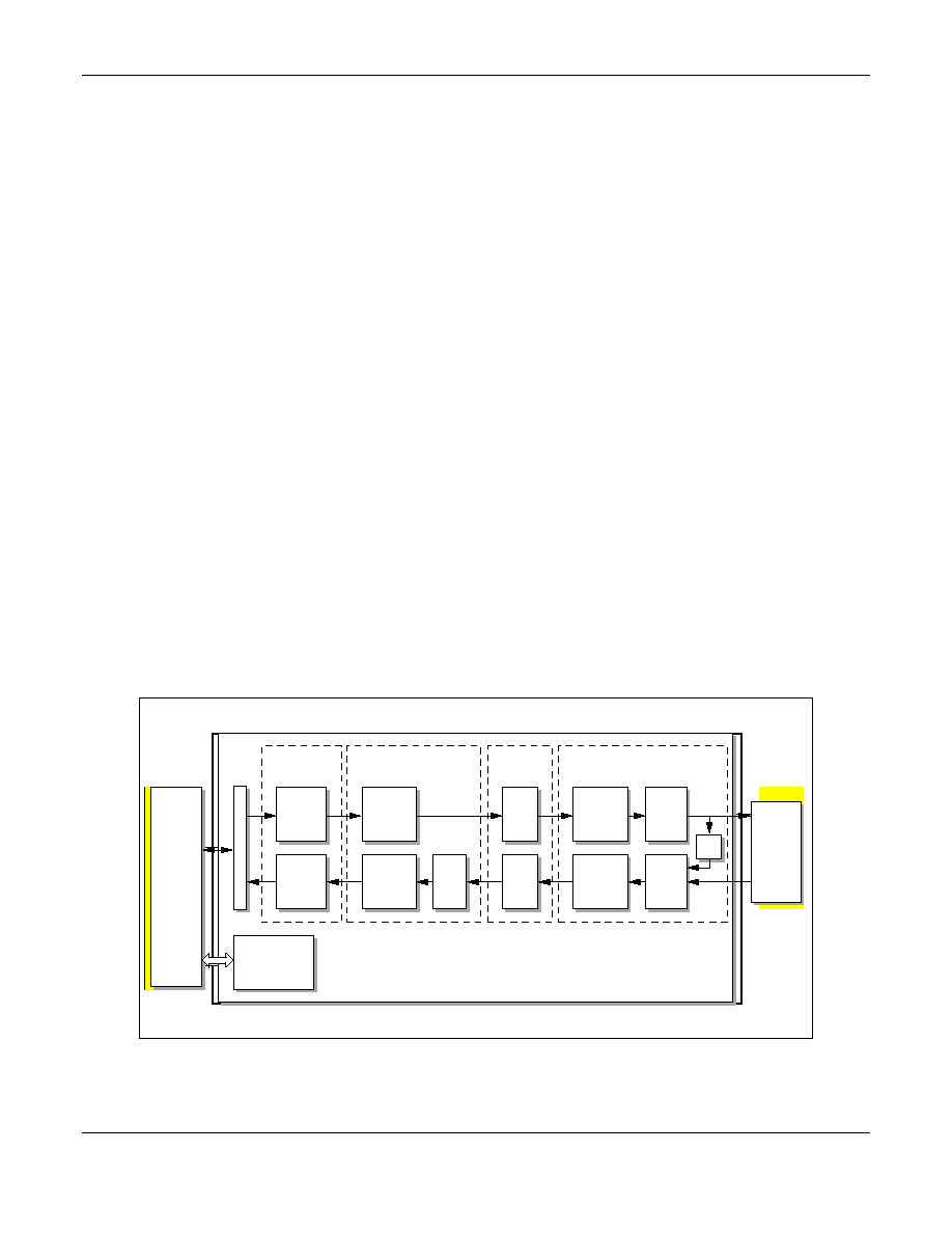
pump are provided in the following sections; refer to
Figure 2.
ATM Transmission Convergence (TC)
In the transmit direction, this block is in charge of
embedding ATM cells into the serial data streams
being fed into the digital interface.
In the receive direction, this block extracts the ATM
cell boundaries from the serial data streams coming
from the digital interface.
To reduce traffic on the PCI bus, the TC block
performs idle cell insertion in the transmit direction
and idle cell deletion and header error correction in
the receive direction.
DSL015002
ATM TC
DI
Transmit
Block
DI
Receive
Block
Digital
Interface (DI)
Bit Parser
and QAM
Encoder
QAM
Decoder
and Bit
Parser
AM EncoderDecoder
FEQ
IFFT
FFT
FFT
Transmit
Filter
Time
Domain
Equalizer
ADC
Intf
AFE Interface
DAC
Intf
PCI
Controller
(P46)
Microcontroller
Interface
AFE
(20431)
DMT Data Pump (11627)
EC
Figure 2. AccessRunner 11627 DMT Data Pump Functional Block Diagram
AccessRunner
Controller-less ADSL Modem Device Set for PCI Applications
4
Conexant
Doc. No. 100394B
Proprietary Information
October 19, 1999
Digital Interface (DI)
The DI Transmit Block performs the following
functions: transmit data multiplexing and buffering,
fast and interleave data stream framing, transmit
data synchronization control, eoc/aoc insertion, CRC
encoding, scrambling, FEC encoding, and data
interleaving.
The DI Receive Block performs the following
functions: data de-interleaving, FEC decoding,
descrambling, CRC check, receive data
synchronization and receive clock generation,
demultiplexing and buffering of receive data and
receive eoc/aoc.
QAM Encoder/Decoder
The QAM Encoder/Decoder performs the following
functions: constellation encoding, clock recovery,
receive gain compensation, frequency domain
equalization (FEQ), slicing, and constellation
decoding. The block also performs other functions
like frequency domain signal processing, signal
power, error power averaging and computations
related to frequency domain training.
FFT
The FFT performs IFFT for modulation of the
transmit symbol, and FFT for demodulation of the
receive symbol.
Analog Front End (AFE) Interface
The AFE Interface performs the following functions:
transmit signal filtering, time domain equalization,
and time domain signal power averaging, and echo
cancellation (EC).
Microcontroller Interface
The microcontroller interface enables the host
computer via the PCI controller to set parameters to
control DSP sequencing and to read/write
coefficients or data.
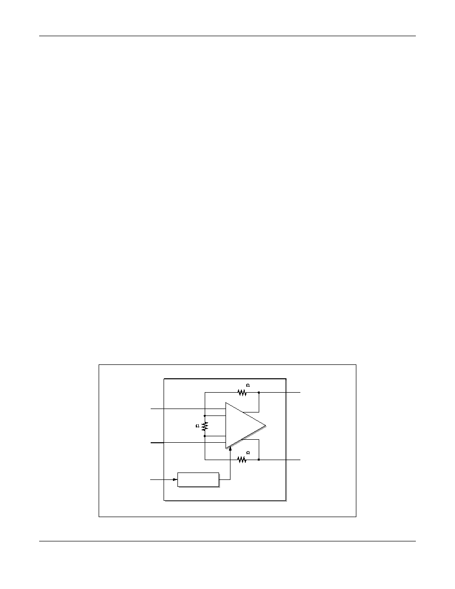
20441 Line Driver
The 20441 line driver is designed for use in full-rate
and G.lite (G.992.2) ADSL modems. It is optimized
for ideal ADSL performance providing low noise,
high bandwidth, and superior linearity. The 20441
line driver transmits a DMT modulated signal in the
25 � 132 kHz band. It operates from a single 5V
�
TBD% supply, refer to
Figure 3.
The driver is optimized for ADSL performance: it has
a very low noise figure, high bandwidth and good
linearity.
(
)
Current Control
Block
Line Driver
(20441)
+
+
+
248.4
248.4
400
OUTP_DRV
OUTM_DRV
INP_DRV
INM_DRV
RBIAS
DSL015_003
Figure 3. AccessRunner 20441 Line Driver
Controller-less ADSL Modem Device Set for PCI Applications
AccessRunner
Doc. No. 100394B
Conexant
5
October 19, 1999
Proprietary Information
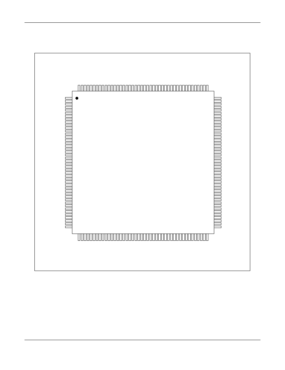
P46 PCI Bus Interface Device Hardware Pins and Signals
The pin assignments for the P46 are shown in Figure 4 and listed in Table 1. The signals are defined in Table 2.
45
46
47
48
49
50
51
52
53
54
55
56
57
58
59
60
61
62
63
64
65
66
67
68
69
70
71
72
73
74
75
76
77
78
79
80
81
82
83
84
85
86
87
88
1 3 2
1 3 1
1 3 0
1 2 9
1 2 8
1 2 7
1 2 6
1 2 5
1 2 4
1 2 3
1 2 2
1 2 1
1 2 0
1 1 9
1 1 8
1 1 7
1 1 6
1 1 5
1 1 4
1 1 3
1 1 2
1 1 1
1 1 0
1 0 9
1 0 8
1 0 7
1 0 6
1 0 5
1 0 4
1 0 3
1 0 2
1 0 1
1 0 0
9 9
9 8
9 7
9 6
9 5
9 4
9 3
9 2
9 1
9 0
8 9
1
2
3
4
5
6
7
8
9
1 0
1 1
1 2
1 3
1 4
1 5
1 6
1 7
1 8
1 9
2 0
2 1
2 2
2 3
2 4
2 5
2 6
2 7
2 8
2 9
3 0
3 1
3 2
3 3
3 4
3 5
3 6
3 7
3 8
3 9
4 0
4 1
4 2
4 3
4 4
176
175
174
173
172
171
170
169
168
167
166
165
164
163
162
161
160
159
158
157
156
155
154
153
152
151
150
149
148
147
146
145
144
143
142
141
140
139
138
137
136
135
134
133
VDD
DP_WR#
DP_A[0]
DP_A[1]
DP_A[2]
DP_A[3]
DP_A[4]
DP_A[5]
DP_A[6]
DP_A[7]
GND
DP_A[8]
DP_A[9]
VDD
DP_IRQ#[0]
DP_IRQ#[1]
AFE_WAKEUP
AFE_CTRLOUT
AFE_CTRLIN
AFE_STB
AFE_SCLK
GND
DP_RDATAS0
DP_RXSOC0
VDD
DP_RCLKAS0
DP_TDATLS0
DP_TXSOC0
DP_TCLKLS0
GND
NC
VDD
PCI_VAUXDET
PCI_VPCIDET
NC
PCI_VAUXEN#
PCI_VPCIEN#
NC
SCANMODE
SCANEN
GND
NC
NC
NC
V D D
PCI_AD[7]
PCI_AD[6]
G N D
PCI_AD[5]
PCI_AD[4]
V D D
PCI_AD[3]
PCI_AD[2]
G N D
PCI_AD[1]
PCI_AD[0]
V D D
P C I _ P M E
E E P R O M _ D I N
E E P R O M _ D O U T
E E P R O M _ C L K
E E P R O M _ C S
V D D
V G G 2
DP_D[0]
DP_D[1]
G N D
DP_D[2]
DP_D[3]
G N D
DP_D[4]
DP_D[5]
V D D
DP_D[6]
DP_D[7]
DP_D[8]
DP_D[9]
DP_D[10]
DP_D[11]
G N D
DP_D[12]
DP_D[13]
V D D
DP_D[14]
DP_D[15]
D P _ C S #
D P _ R D #
G N D
VDD
PCI_AD[24]
PCI_CBE#[3]
PCI_IDSEL
GND
PCI_AD[23]
PCI_AD[22]
VDD
PCI_AD[21]
PCI_AD[20]
GND
PCI_AD[19]
PCI_AD[18]
VDD
PCI_AD[17]
PCI_AD[16]
GND
PCI_AD[15]
PCI_CBE#[2]
VDD
PCI_FRAME#
PCI_IRDY#
GND
PCI_TRDY#
PCI_DEVSEL#
PCI_STOP#
PCI_PERR#
VDD
PCI_SERR#
PCI_PAR
PCI_CBE#[1]
GND
PCI_AD[14]
PCI_AD[13]
VDD
PCI_AD[12]
PCI_AD[11]
GND
PCI_AD[10]
PCI_AD[9]
VDD
PCI_AD[8]
PCI_CBE#[0]
GND
P C I _ I N T A #
P C I _ R S T #
V D D
P C I _ C L K
G N D
P C I _ G N T #
P C I _ R E Q #
PCI_AD[31]
V D D
PCI_AD[30]
PCI_AD[29]
G N D
PCI_AD[28]
PCI_AD[27]
V D D
PCI_AD[26]
PCI_AD[25]
G N D
V G G 1
V D D
G P I N 0
G P I N 1
GPIO[0]
GPIO[1]
GPIO[2]
GPIO[3]
G N D
V D D
GPIO[4]
GPIO[5]
GPIO[6]
GPIO[7]
G N D
V D D
GPIO[8]
G N D
TDI_GPIO[9]
T M S _ G P I O [ 1 0 ]
V D D
T R S T N _ G P I O [ 1 1 ]
R E F C L K
P C I _ V P C I P R E F E R
T C K
T D O
DSL015004
Figure 4. P46 Pinout Diagram