Data Sheet
N8370DSE
June 30, 1999
Bt8370/8375/8376
Fully Integrated T1/E1 Framer and Line Interface
The Bt8370/8375/8376 is a family of single chip transceivers for T1/E1 and Integrated
Service Digital Network (ISDN) primary rate interfaces, operating at 1.544 Mbps or
2.048 Mbps. These devices combine a sophisticated framer, transmit and receive slip
buffers, and an on-chip physical line interface to provide a complete T1/E1 transceiver.
The fully featured Bt8370 and short-haul Bt8375 and Bt8376 devices provide a
programmable clock rate adapter for simplifying system bus interfacing. The adapter
synthesizes standard clock signals from the receive or transmit line rate clocks or from an
external reference.
Operations are controlled through memory-mapped registers accessible via a parallel
microprocessor port. Current ANSI, ETSI, ITU-T, and Bellcore standards are supported for
alarm and error monitoring, signaling supervision (e.g., LAPD/SS7), per-channel trunk
conditioning, and Facility Data Link (FDL) maintenance. A serial Time Division Multiplexed
(TDM) system bus interface allows the backplane Pulse Code Modulation (PCM) data
highway to operate at rates from 1.536 to 8.192 Mbps. Extensive test and diagnostic
functions include a full set of digital and analog loopbacks, PRBS test pattern generation,
BER meter, and forced error insertion.
The physical line interface circuit recovers clock and data from analog signals with +3 to
≠43 dB cable attenuation, appropriate for both short (≠18 dB) and long-haul T1/E1
applications. Receive line equalization (EQ) and transmit Line Build Out (LBO) filters are
implemented using Digital Signal Processor (DSP) circuits for reliable performance. Data
and/or clock jitter attenuation can be inserted on either the receive or transmit path. The
transmit section includes precision pulse shaping and amplitude pre-emphasis for cross
connect applications, as well as a set of LBO filters for long-haul Channel Service Unit
(CSU) applications. A complementary driver output is provided to couple 75/100/120
lines via an external transformer.
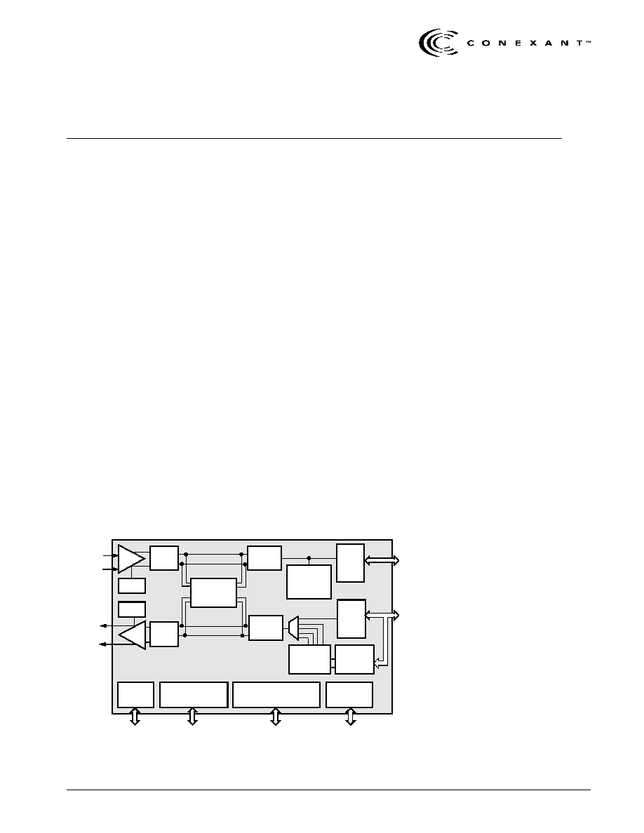
Functional Block Diagram
Receive
System
Bus
Transmit
System
Bus
CLAD I/O
Dual-Rail/NRZ/
External DL3
Motorola/Intel
Processor Bus
Test Port
Receive
Analog
Transmit
Analog
T1/E1
Transmit
Framer
TX
Slip
Buffer
RX
Slip
Buffer
T1/E1
Receive
Framer
Overhead
Insertion
Clock Rate
Adaptor
Control/Status
Registers
JTAG
Data Link Controllers
DL1 + DL2
EQ
RPLL
Pulse
LBO
TPLL
TX or RX
Jitter
Attenuator
ZCS
Decode
ZCS
Encode
RX
TX
Distinguishing Features
∑
Single-chip T1/E1 framer with
short/long-haul physical line
interface
∑
Frames to popular T1/E1 standards:
≠ T1: SF, ESF, SLC
96, T1DM
≠ E1: PCM
-
30, G.704, G.706, G.732
ISDN primary rate
∑
On-chip physical line interface
compatible with:
≠ DSX-1/E1 short-haul signals
≠ DS-1 (T1.403) and ETSI long-haul
signals
∑
Two-frame transmit and receive PCM
slip buffers
∑
Clock rate adapter synthesizes jitter
attenuated system clocks from an
internal or external reference
∑
Parallel 8-bit microprocessor port
supports Intel or Motorola buses
∑
Automated Facility Data Link (FDL)
management
∑
BERT generation and counting
∑
Two full-duplex HDLC controllers for
data link and LAPD/SS7 signaling
∑
B8ZS/HDB3/Bit 7 zero suppression
∑
80-pin MQFP surface-mount package
∑
Operates from a single +5 Vdc ±5%
power supply
∑
Low-power CMOS technology
Applications
∑
T1/E1 Channel Service Unit/Data
Service Unit (CSU/DSU)
∑
Digital Access Cross-Connect
Systems (DACS)
∑
T1/E1 Multiplexer (MUX)
∑
PBXs and PCM channel bank
∑
T1/E1 HDSL terminal unit
∑
ISDN Primary Rate Access (PRA)
N8370DSE
Conexant
Information provided by Conexant Systems, Inc. (Conexant) is believed to be accurate and reliable. However, no responsibility is
assumed by Conexant for its use, nor any infringement of patents or other rights of third parties which may result from its use. No
license is granted by implication or otherwise under any patent rights of Conexant other than for circuitry embodied in Conexant
products. Conexant reserves the right to change circuitry at any time without notice. This document is subject to change without
notice.
Conexant and "What's Next in Communications Technologies" are trademarks of Conexant Systems, Inc.
Product names or services listed in this publication are for identification purposes only, and may be trademarks or registered
trademarks of their respective companies. All other marks mentioned herein are the property of their respective holders.
© 1999 Conexant Systems, Inc.
Printed in U.S.A.
All Rights Reserved
Reader Response: To improve the quality of our publications, we welcome your feedback. Please send comments or
suggestions via e-mail to
Conexant Reader Response@conexant.com
. Sorry, we can't answer your technical
questions at this address. Please contact your local Conexant
sales office
or applications engineer if you have
technical questions.
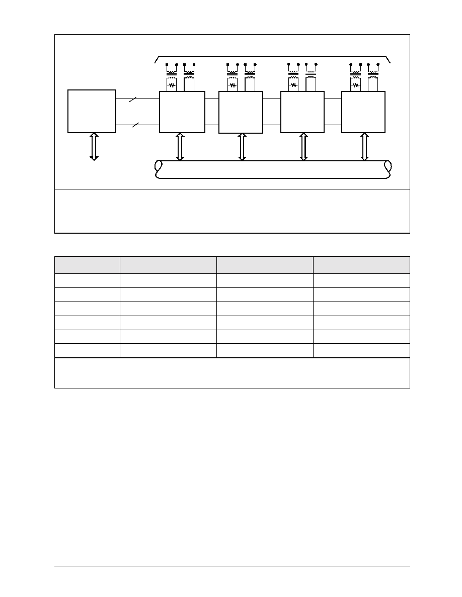
Bt8370EVM--Bt8370 Evaluation Module, Quad T1/E1 ISDN PRI Board
Ordering Information
An evaluation module is available and provides a convenient platform to test and evaluate Bt8370 performance and fea-
tures. The Bt8370EVM provides up to four T1/E1 transceivers, all necessary line interface circuitry for T1 and E1 con-
nections, and a simple RS232 serial user interface for setting device parameters and displaying status information on
any VT100 compatible terminal. Contact the local sales representative for ordering information and pricing.
Model Number
Package
Operating Temperature
Reduced Features
(1)
Bt8370EPF
80-Pin MQFP
≠40 to 85 ∞C
none
Bt8370KPF
80-Pin MQFP
0 to 70 ∞C
none
Bt8375EPF
80-Pin MQFP
≠40 to 85 ∞C
Short-Haul
Bt8375KPF
80-Pin MQFP
0 to 70 ∞C
Short-Haul
Bt8376EPF
80-Pin MQFP
≠40 to 85 ∞C
Short-Haul, No CLAD output
Bt8376KPF
80-Pin MQFP
0 to 70 ∞C
Short-Haul, No CLAD output
NOTE(S):
(1)
Cost reduced Bt8375 and Bt8376 are pin and register-compatible versions of Bt8370 with reduced features. Contact the local
sales representative for ordering information and pricing.
Bt8370
Local PCM Highway (128 Channel, 8 MHz)
Address
Data Bus
9
8
MC68302
Microprocessor
Bt8370
Bus
T1 or E1 connection at DSX or CSU levels
Bt8370
Bt8370
Bt8370
RS232 User
Interface

N8370DSE
Conexant
iii
Table of Contents
List of Figures
. . . . . . . . . . . . . . . . . . . . . . . . . . . . . . . . . . . . . . . . . . . . . . . . . . . . . . . . . . . . . . . . . . . . . . . . xii
List of Tables
. . . . . . . . . . . . . . . . . . . . . . . . . . . . . . . . . . . . . . . . . . . . . . . . . . . . . . . . . . . . . . . . . . . . . . . . . xv
1.0
Pin Descriptions
. . . . . . . . . . . . . . . . . . . . . . . . . . . . . . . . . . . . . . . . . . . . . . . . . . . . . . . . . . . . . . . . 1-1
1.1
Pin Assignments
. . . . . . . . . . . . . . . . . . . . . . . . . . . . . . . . . . . . . . . . . . . . . . . . . . . . . . . . . . . . 1-1
2.0
Circuit Description
. . . . . . . . . . . . . . . . . . . . . . . . . . . . . . . . . . . . . . . . . . . . . . . . . . . . . . . . . . . . . . 2-1
2.1
Bt8370/8375/8376 Block Diagrams
. . . . . . . . . . . . . . . . . . . . . . . . . . . . . . . . . . . . . . . . . . . . . . 2-1
2.2
Receive Line Interface Unit
. . . . . . . . . . . . . . . . . . . . . . . . . . . . . . . . . . . . . . . . . . . . . . . . . . . . 2-5
2.2.1
Data Recovery
. . . . . . . . . . . . . . . . . . . . . . . . . . . . . . . . . . . . . . . . . . . . . . . . . . . . . . . . 2-7
2.2.1.1
Automatic Gain Control
. . . . . . . . . . . . . . . . . . . . . . . . . . . . . . . . . . . . . . . . . 2-7
2.2.1.2
Variable Gain Amplifier
. . . . . . . . . . . . . . . . . . . . . . . . . . . . . . . . . . . . . . . . . 2-7
2.2.1.3
Adaptive Equalizer
. . . . . . . . . . . . . . . . . . . . . . . . . . . . . . . . . . . . . . . . . . . . . 2-7
2.2.1.4
Data Slicer
. . . . . . . . . . . . . . . . . . . . . . . . . . . . . . . . . . . . . . . . . . . . . . . . . . 2-7
2.2.2
Clock Recovery
. . . . . . . . . . . . . . . . . . . . . . . . . . . . . . . . . . . . . . . . . . . . . . . . . . . . . . . 2-8
2.2.2.1
Phase Locked Loop
. . . . . . . . . . . . . . . . . . . . . . . . . . . . . . . . . . . . . . . . . . . . 2-8
2.3
Jitter Attenuator
. . . . . . . . . . . . . . . . . . . . . . . . . . . . . . . . . . . . . . . . . . . . . . . . . . . . . . . . . . . . 2-9
2.3.1
Elastic Store
. . . . . . . . . . . . . . . . . . . . . . . . . . . . . . . . . . . . . . . . . . . . . . . . . . . . . . . . . 2-10
2.4
Receiver
. . . . . . . . . . . . . . . . . . . . . . . . . . . . . . . . . . . . . . . . . . . . . . . . . . . . . . . . . . . . . . . . . 2-14
2.4.1
ZCS Decoder
. . . . . . . . . . . . . . . . . . . . . . . . . . . . . . . . . . . . . . . . . . . . . . . . . . . . . . . . 2-15
2.4.2
In-Band Loopback Code Detection
. . . . . . . . . . . . . . . . . . . . . . . . . . . . . . . . . . . . . . . . 2-15
2.4.3
Error Counters
. . . . . . . . . . . . . . . . . . . . . . . . . . . . . . . . . . . . . . . . . . . . . . . . . . . . . . . 2-16
2.4.3.1
Frame Bit Error Counter
. . . . . . . . . . . . . . . . . . . . . . . . . . . . . . . . . . . . . . . . 2-16
2.4.3.2
CRC Error Counter
. . . . . . . . . . . . . . . . . . . . . . . . . . . . . . . . . . . . . . . . . . . 2-16
2.4.3.3
LCV Error Counter
. . . . . . . . . . . . . . . . . . . . . . . . . . . . . . . . . . . . . . . . . . . . 2-16
2.4.3.4
FEBE Counter
. . . . . . . . . . . . . . . . . . . . . . . . . . . . . . . . . . . . . . . . . . . . . . . 2-16
2.4.4
Error Monitor
. . . . . . . . . . . . . . . . . . . . . . . . . . . . . . . . . . . . . . . . . . . . . . . . . . . . . . . . 2-17

Table of Contents
Bt8370/8375/8376
Fully Integrated T1/E1 Framer and Line Interface
iv
Conexant
N8370DSE
2.4.5
Alarm Monitor
. . . . . . . . . . . . . . . . . . . . . . . . . . . . . . . . . . . . . . . . . . . . . . . . . . . . . . . 2-18
2.4.5.1
Loss of Frame
. . . . . . . . . . . . . . . . . . . . . . . . . . . . . . . . . . . . . . . . . . . . . . . 2-18
2.4.5.2
Loss of Signal
. . . . . . . . . . . . . . . . . . . . . . . . . . . . . . . . . . . . . . . . . . . . . . . 2-18
2.4.5.3
Analog Loss of Signal
. . . . . . . . . . . . . . . . . . . . . . . . . . . . . . . . . . . . . . . . . 2-19
2.4.5.4
Alarm Indication Signal
. . . . . . . . . . . . . . . . . . . . . . . . . . . . . . . . . . . . . . . . 2-19
2.4.5.5
Yellow Alarm
. . . . . . . . . . . . . . . . . . . . . . . . . . . . . . . . . . . . . . . . . . . . . . . . 2-19
2.4.5.6
Multiframe YEL
. . . . . . . . . . . . . . . . . . . . . . . . . . . . . . . . . . . . . . . . . . . . . . 2-19
2.4.5.7
Severely Errored Frame
. . . . . . . . . . . . . . . . . . . . . . . . . . . . . . . . . . . . . . . . 2-19
2.4.5.8
Change of Frame Alignment
. . . . . . . . . . . . . . . . . . . . . . . . . . . . . . . . . . . . . 2-19
2.4.5.9
Receive Multiframe AIS
. . . . . . . . . . . . . . . . . . . . . . . . . . . . . . . . . . . . . . . . 2-19
2.4.6
Test Pattern Receiver
. . . . . . . . . . . . . . . . . . . . . . . . . . . . . . . . . . . . . . . . . . . . . . . . . . 2-20
2.4.7
Receive Framing
. . . . . . . . . . . . . . . . . . . . . . . . . . . . . . . . . . . . . . . . . . . . . . . . . . . . . . 2-21
2.4.8
External Receive Data Link
. . . . . . . . . . . . . . . . . . . . . . . . . . . . . . . . . . . . . . . . . . . . . . 2-26
2.4.9
Sa-Byte Receive Buffers
. . . . . . . . . . . . . . . . . . . . . . . . . . . . . . . . . . . . . . . . . . . . . . . . 2-26
2.4.10
Receive Data Link
. . . . . . . . . . . . . . . . . . . . . . . . . . . . . . . . . . . . . . . . . . . . . . . . . . . . . 2-26
2.4.10.1
Data Link Controllers
. . . . . . . . . . . . . . . . . . . . . . . . . . . . . . . . . . . . . . . . . . 2-27
2.4.10.2
RBOP Receiver
. . . . . . . . . . . . . . . . . . . . . . . . . . . . . . . . . . . . . . . . . . . . . . 2-31
2.5
Receive System Bus
. . . . . . . . . . . . . . . . . . . . . . . . . . . . . . . . . . . . . . . . . . . . . . . . . . . . . . . . 2-32
2.5.1
Timebase
. . . . . . . . . . . . . . . . . . . . . . . . . . . . . . . . . . . . . . . . . . . . . . . . . . . . . . . . . . . 2-35
2.5.2
Slip Buffer
. . . . . . . . . . . . . . . . . . . . . . . . . . . . . . . . . . . . . . . . . . . . . . . . . . . . . . . . . . 2-36
2.5.3
Signaling Buffer
. . . . . . . . . . . . . . . . . . . . . . . . . . . . . . . . . . . . . . . . . . . . . . . . . . . . . . 2-37
2.5.4
Signaling Stack
. . . . . . . . . . . . . . . . . . . . . . . . . . . . . . . . . . . . . . . . . . . . . . . . . . . . . . 2-38
2.5.5
Embedded Framing
. . . . . . . . . . . . . . . . . . . . . . . . . . . . . . . . . . . . . . . . . . . . . . . . . . . 2-38
2.6
Clock Rate Adapter
. . . . . . . . . . . . . . . . . . . . . . . . . . . . . . . . . . . . . . . . . . . . . . . . . . . . . . . . . 2-39
2.6.1
Configuring the CLAD Registers
. . . . . . . . . . . . . . . . . . . . . . . . . . . . . . . . . . . . . . . . . . 2-43
2.7
Transmit System Bus
. . . . . . . . . . . . . . . . . . . . . . . . . . . . . . . . . . . . . . . . . . . . . . . . . . . . . . . . 2-46
2.7.1
Timebase
. . . . . . . . . . . . . . . . . . . . . . . . . . . . . . . . . . . . . . . . . . . . . . . . . . . . . . . . . . . 2-48
2.7.2
Slip Buffer
. . . . . . . . . . . . . . . . . . . . . . . . . . . . . . . . . . . . . . . . . . . . . . . . . . . . . . . . . . 2-48
2.7.3
Signaling Buffer
. . . . . . . . . . . . . . . . . . . . . . . . . . . . . . . . . . . . . . . . . . . . . . . . . . . . . . 2-49
2.7.4
Transmit Framing
. . . . . . . . . . . . . . . . . . . . . . . . . . . . . . . . . . . . . . . . . . . . . . . . . . . . . 2-50
2.7.5
Embedded Framing
. . . . . . . . . . . . . . . . . . . . . . . . . . . . . . . . . . . . . . . . . . . . . . . . . . . 2-52
2.8
Transmitter
. . . . . . . . . . . . . . . . . . . . . . . . . . . . . . . . . . . . . . . . . . . . . . . . . . . . . . . . . . . . . . . 2-53
2.8.1
External Transmit Data Link
. . . . . . . . . . . . . . . . . . . . . . . . . . . . . . . . . . . . . . . . . . . . . 2-54
2.8.2
Transmit Data Links
. . . . . . . . . . . . . . . . . . . . . . . . . . . . . . . . . . . . . . . . . . . . . . . . . . . 2-54
2.8.2.1
Data Link Controllers
. . . . . . . . . . . . . . . . . . . . . . . . . . . . . . . . . . . . . . . . . . 2-54
2.8.2.2
PRM Generator
. . . . . . . . . . . . . . . . . . . . . . . . . . . . . . . . . . . . . . . . . . . . . . 2-59
2.8.3
Sa-Byte Overwrite Buffer
. . . . . . . . . . . . . . . . . . . . . . . . . . . . . . . . . . . . . . . . . . . . . . . 2-59
2.8.4
Overhead Pattern Generator
. . . . . . . . . . . . . . . . . . . . . . . . . . . . . . . . . . . . . . . . . . . . . 2-60
2.8.4.1
Framing Pattern Generation
. . . . . . . . . . . . . . . . . . . . . . . . . . . . . . . . . . . . . 2-60
2.8.4.2
Alarm Generator
. . . . . . . . . . . . . . . . . . . . . . . . . . . . . . . . . . . . . . . . . . . . . 2-60
2.8.4.3
CRC Generation
. . . . . . . . . . . . . . . . . . . . . . . . . . . . . . . . . . . . . . . . . . . . . 2-63
2.8.4.4
Far-End Block Error Generation
. . . . . . . . . . . . . . . . . . . . . . . . . . . . . . . . . . 2-63

Bt8370/8375/8376
Table of Contents
Fully Integrated T1/E1 Framer and Line Interface
N8370DSE
Conexant
v
2.8.5
Test Pattern Generator
. . . . . . . . . . . . . . . . . . . . . . . . . . . . . . . . . . . . . . . . . . . . . . . . . 2-63
2.8.6
Transmit Error Insertion
. . . . . . . . . . . . . . . . . . . . . . . . . . . . . . . . . . . . . . . . . . . . . . . . 2-64
2.8.7
In-Band Loopback Code Generator
. . . . . . . . . . . . . . . . . . . . . . . . . . . . . . . . . . . . . . . . 2-65
2.8.8
ZCS Encoder
. . . . . . . . . . . . . . . . . . . . . . . . . . . . . . . . . . . . . . . . . . . . . . . . . . . . . . . . 2-65
2.9
Transmit Line Interface Unit
. . . . . . . . . . . . . . . . . . . . . . . . . . . . . . . . . . . . . . . . . . . . . . . . . . 2-68
2.9.1
Pulse Shape
. . . . . . . . . . . . . . . . . . . . . . . . . . . . . . . . . . . . . . . . . . . . . . . . . . . . . . . . . 2-70
2.9.2
Transmit Phase Lock Loop
. . . . . . . . . . . . . . . . . . . . . . . . . . . . . . . . . . . . . . . . . . . . . . 2-76
2.9.2.1
Clock Reference
. . . . . . . . . . . . . . . . . . . . . . . . . . . . . . . . . . . . . . . . . . . . . 2-76
2.9.2.2
Output Jitter
. . . . . . . . . . . . . . . . . . . . . . . . . . . . . . . . . . . . . . . . . . . . . . . . 2-77
2.9.3
Line Build Out
. . . . . . . . . . . . . . . . . . . . . . . . . . . . . . . . . . . . . . . . . . . . . . . . . . . . . . . 2-77
2.9.4
Line Driver
. . . . . . . . . . . . . . . . . . . . . . . . . . . . . . . . . . . . . . . . . . . . . . . . . . . . . . . . . . 2-80
2.9.4.1
Termination Impedance
. . . . . . . . . . . . . . . . . . . . . . . . . . . . . . . . . . . . . . . . 2-80
2.9.4.2
Return Loss
. . . . . . . . . . . . . . . . . . . . . . . . . . . . . . . . . . . . . . . . . . . . . . . . 2-81
2.9.4.3
Output Enable
. . . . . . . . . . . . . . . . . . . . . . . . . . . . . . . . . . . . . . . . . . . . . . . 2-82
2.9.5
Pulse Imbalance
. . . . . . . . . . . . . . . . . . . . . . . . . . . . . . . . . . . . . . . . . . . . . . . . . . . . . . 2-82
2.10 Microprocessor Interface
. . . . . . . . . . . . . . . . . . . . . . . . . . . . . . . . . . . . . . . . . . . . . . . . . . . . 2-83
2.10.1
Address/Data Bus
. . . . . . . . . . . . . . . . . . . . . . . . . . . . . . . . . . . . . . . . . . . . . . . . . . . . . 2-84
2.10.2
Bus Control Signals
. . . . . . . . . . . . . . . . . . . . . . . . . . . . . . . . . . . . . . . . . . . . . . . . . . . 2-84
2.10.3
Interrupt Requests
. . . . . . . . . . . . . . . . . . . . . . . . . . . . . . . . . . . . . . . . . . . . . . . . . . . . 2-84
2.10.4
Device Reset
. . . . . . . . . . . . . . . . . . . . . . . . . . . . . . . . . . . . . . . . . . . . . . . . . . . . . . . . 2-85
2.10.4.1
Power-On Reset (POR)
. . . . . . . . . . . . . . . . . . . . . . . . . . . . . . . . . . . . . . . . 2-85
2.10.4.2
Hardware Reset
. . . . . . . . . . . . . . . . . . . . . . . . . . . . . . . . . . . . . . . . . . . . . 2-85
2.10.4.3
Software Reset
. . . . . . . . . . . . . . . . . . . . . . . . . . . . . . . . . . . . . . . . . . . . . . 2-85
2.11 Loopbacks
. . . . . . . . . . . . . . . . . . . . . . . . . . . . . . . . . . . . . . . . . . . . . . . . . . . . . . . . . . . . . . . . 2-86
2.11.1
Remote Line Loopback
. . . . . . . . . . . . . . . . . . . . . . . . . . . . . . . . . . . . . . . . . . . . . . . . . 2-86
2.11.2
Remote Payload Loopback
. . . . . . . . . . . . . . . . . . . . . . . . . . . . . . . . . . . . . . . . . . . . . . 2-86
2.11.3
Remote Per-Channel Loopbacks
. . . . . . . . . . . . . . . . . . . . . . . . . . . . . . . . . . . . . . . . . . 2-86
2.11.4
Local Analog Loopback
. . . . . . . . . . . . . . . . . . . . . . . . . . . . . . . . . . . . . . . . . . . . . . . . 2-87
2.11.5
Local Framer Loopback
. . . . . . . . . . . . . . . . . . . . . . . . . . . . . . . . . . . . . . . . . . . . . . . . 2-87
2.11.6
Local Per-Channel Loopback
. . . . . . . . . . . . . . . . . . . . . . . . . . . . . . . . . . . . . . . . . . . . . 2-87
2.12 Joint Test Access Group
. . . . . . . . . . . . . . . . . . . . . . . . . . . . . . . . . . . . . . . . . . . . . . . . . . . . . 2-88
2.12.1
Instructions
. . . . . . . . . . . . . . . . . . . . . . . . . . . . . . . . . . . . . . . . . . . . . . . . . . . . . . . . . 2-88
2.12.2
Device Identification Register
. . . . . . . . . . . . . . . . . . . . . . . . . . . . . . . . . . . . . . . . . . . . 2-89