
TM
Virtual Components for the Converging World
Amphion continues to expand its family of application-specific cores
1
See http://www.amphion.com for a current list of products
CS2410
8-1024 Point FFT/IFFT
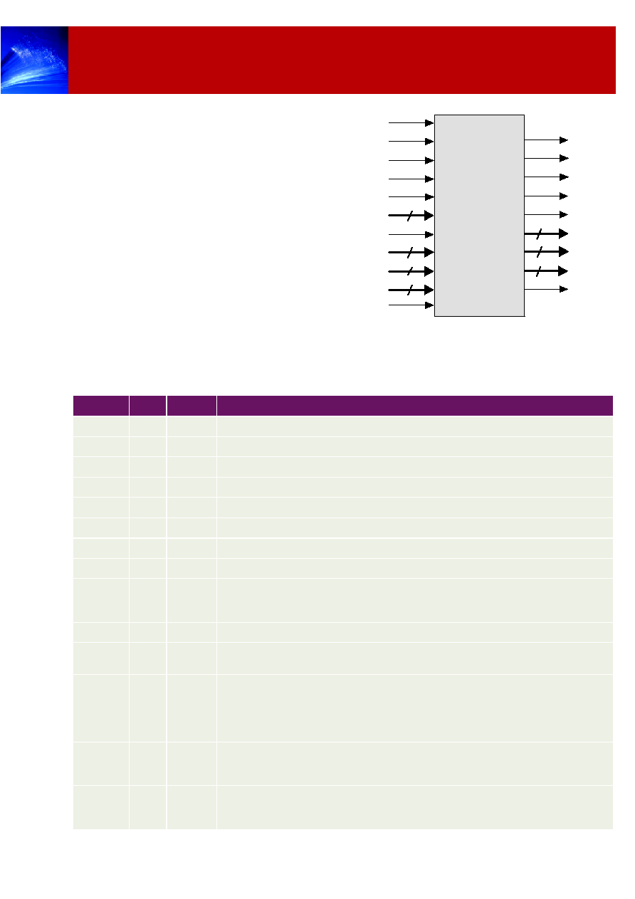
The CS2410 is an online programmable 8 - 1024-point FFT/IFFT core. It is based on the radix-4 algorithm and
performs 8-point to 1024-point FFT/IFFT computation in multiple computation passes. A block diagram of the
core is given in Figure 1.
Figure 1: CS2410 Block Diagram
Radix-4 Processor
Radix-4
Butterfly
Radix-4/
Radix-2
Selectable
Butterfly
1024-word
dual-port
memory
I/O interface and transform control
Memory
controller
X
Mux
Twiddle
LUT
Complex
Number
Multiplier
Y
FEATURES
On-line programmable FFT/IFFT core
16-bit complex input/output in two's
complement format (32-bit complex word)
16-bit twiddle factors generated inside the
core
18-bit internal accuracy
Block-floating point arithmetic achieving high
accuracy and dynamic range
Mixed radix-4/radix-8/radix-16 architecture
Both input and output in normal order
Built-in block-floating point to fixed point
converter
No external memory required
Optimized for both ASIC and FPGA
technologies with the same functionality
KEY METRICS
Logic:
39k gates
Memory:
<0.7mm
2
Total area:
<1.1mm
2
See Table 6 - 8 for more details.
APPLICATIONS
Image processing
Atmospheric imaging
Spectral representation
OFDM modulation scheme for:
-
ADSL (up to 256 point) Ref: ANSI T1.413
-
802.11a (64 point) Ref: IEEE 802.11a
2
CS2410
8-1024 Point FFT/IFFT
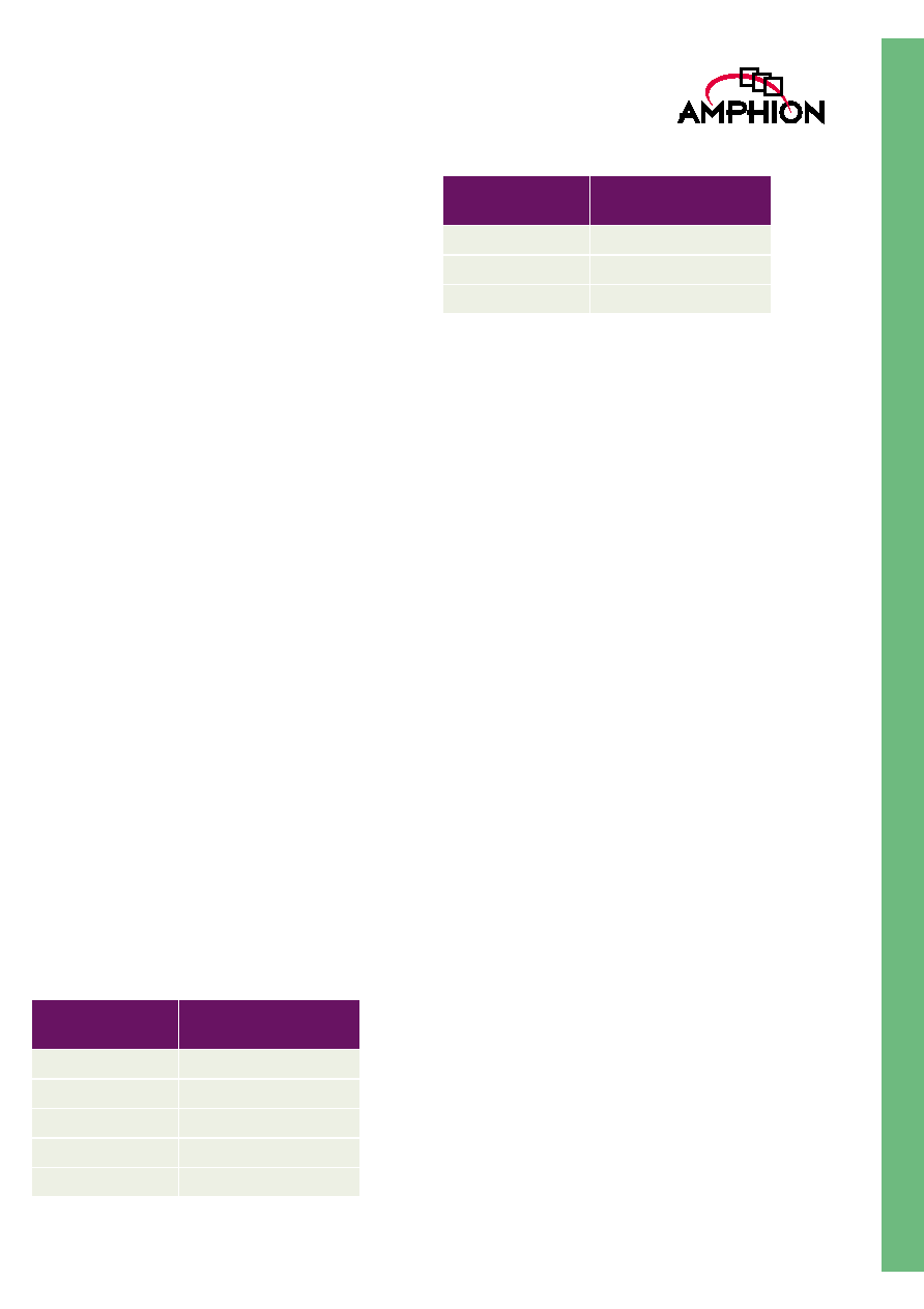
CS2310 I/O SIGNAL DESCRIPTION
Table 1 provides a description of the input and output ports
(shown graphically in Figure 2) of the CS2410 Programmable
8-1024 Point FFT/IFFT core. Unless otherwise stated all signals
are active High, and bit (0) is the least significant bit
.
Figure 2: CS2410 Symbol
CS2410
8- 1024pt
FFT/IFFT
CLK
NotRST
CLR
IFFT
OpMode
CFG
3
XRe
16
XBS
XIm
16
YSC
4
BIP
YRe
16
YIm
16
YExp
4
YBS
YAV
YOV
Busy
Done
YEnab
Table 1: CS2410 I/O Description
Name
I/O
Width
Description
CLK
I
1
Clock signal, rising edge active
NotRST
I
1
Asynchronous global reset signal, active LOW
CLR
I
1
Clear (synchronous reset) and programming signal, active HIGH
IFFT
I
1
Programming signal specifying the transform type, loaded when CLR is active
CFG
I
3
Programming signal specifying the transform size, loaded when CLR is active
OpMode
I
1
Programming signal specifying the output mode, loaded when CLR is active
XRe
I
16
Real component of input data X, in two's complement format
XIm
I
16
Imaginary component of input data X, in two's complement format
XBS
I
1
Input data X block start signal, active HIGH, associated with the first input data of the N-
point block. The remaining N-1 data of the N-point data block are loaded into the core in the
following N-1 clock cycles in the natural order.
YEnab
I
1
Output data Y enable control, active HIGH, applicable to separate I/O mode only.
YSC
I
4
Output data Y scaling control, in unsigned binary format, the difference between YSC and
YExp indicating the number of bits of the output mantissa components are shifted.
BIP
O
1
Output signal indicating loading X block or downloading Y block is in Progress. When load-
ing, BIP goes to HIGH the next clock cycle when XBS is active and returns to LOW when
the last data of the N-point block is loaded into the core. When downloading, BIP goes to
HIGH when the core starts reading the transformed result from its memory and returns to
LOW when the reading is completed. XBS is ignored when it is HIGH.
Busy
O
1
Output signal indicating the transform in progress (busy). It goes to HIGH the next clock
cycle when the last data of the N-point block is loaded into the core and returns to LOW
when the transform is completed. XBS is ignored when it is HIGH.
Done
O
1
Output signal indicating the transform completed. It goes to HIGH when the transform is
completed and returns to LOW when loading a new data block or downloading the trans-
formed result is started.

3
TM
GENERAL DESCRIPTION
The CS2410 performs N-point FFT/IFFT following the
equations below:
Where N is 8, 16, 32... or 1024, S is a scaling factor, X(n) is the
complex input data and Y(k) the complex output data. For
transforms of 8-, 32-, 128- and 512-point, the scaling factor S is
2. For transforms of other sizes, the scaling factor S is 4.
Both the real and imaginary components of input X(n) are in
two's complement format. The output Y(k) is in the block-
floating point format, that is, it consists of three components,
namely, the common exponential component for the N-point
data block, the real and the imaginary mantissa components
for every Y(k) of the N-point data block. This format enables
the core to maintain the dynamic range of the transform result
in computation without much loss of accuracy.
The CS2410 uses one Radix-4 FFT processor and one Radix-2/
Radix-4 selectable butterfly to perform the transform in
multiple passes. For example, when performing a 128-point
transform, the core uses three passes to complete the
computation. In the first two passes, the radix-4 operation is
performed and the Radix-4/Radix-2 selectable butterfly is
bypassed. In the final pass, the selectable butterfly is enabled.
It performs a radix-2 operation on the result generated by the
radix-4 processor. Therefore, the radix-8 computation actually
takes place in the final pass.
Programming CS2410 is performed when the synchronous
reset signal CLR is active. The programming signals, namely,
IFFT, CFG and OpMode, are loaded into the core. These set up
the transform type, transform size and data I/O mode.
The CS2410 computes the transform using block-floating
point arithmetic to handle the possible wordlength growth
during the computation. This achieves the maximal accuracy
possible while maintaining the full dynamic range for the
output.
The input data is burst in and the transformed result is burst
out from CS2410 on block-by-block basis. CS2410 has two I/O
modes: simultaneous I/O mode and separate I/O mode. In the
simultaneous I/O mode, the transformed result is
downloaded from the core while the data for the next
transform is loaded. This reduces the waiting time of the core
and is suitable for applications where high throughput rate is
required. In the separate I/O mode, loading input data and
downloading transformed result are performed separately
under the control of two input signals. This is suitable for
systems where only one data bus is available.
Block-floating point to fixed-point converters have been built
inside the CS2410 core. When the transformed result is
downloaded from the core, the conversion is performed
automatically, according to the control signal YSC.
YBS
O
1
Output data Y block start signal, active HIGH, asserted when the first data of the N-point
transformed block is on the output port. The remaining N-1 data of the N-point data block
come out of the core in the following N-1 clock cycles in the natural order.
YAV
O
1
Output data Y available indicator, active HIGH, asserted with every data of the N-point
transform result block
YRe
O
16
Real mantissa component of output data Y, in two's complement format, valid only when
YAV is HIGH
YIm
O
16
Imaginary mantissa component of output data Y, in two's complement format, valid only
when YAV is HIGH
YExp
O
4
Block exponential component of output data Y, in unsigned binary format, valid only when
output signals Done or YBS is HIGH
YOV
O
1
Output data Y scaling overflow signal, active HIGH, asserted when overflow occurs on the
output data because of the scaling specified by input signal YSC. The overflow data is sat-
urated.
Table 1: CS2410 I/O Description
Name
I/O
Width
Description
Y k
( )
1
S
---
X n
( )W
N
nk
�
,k=0, 1, 2,...N-1 [1]
n
0
=
N 1
�
=
Y k
( )
1
S
---
X n
( )W
N
nk
,k=0, 1, 2,...N-1 [2]
n
0
=
N 1
�
=

4
CS2410
8-1024 Point FFT/IFFT
FUNCTIONAL DESCRIPTION
GENERAL
The CS2410 performs a mixed decimation in frequency (DIF),
radix-4, radix-8 and radix-16, forward or inverse Fast Fourier
Transform on complex data. The computation is done in
multiple passes. Data is loaded into the workspace in normal
sequential (natural) order. The transformed data comes out
from the core also in the natural order.
The core is on-line programmable on the transform type,
transform size and the I/O mode. The input and output data
and the twiddle factor wordlengths are selected such that it
can be used in a wide range of applications.
The core computes the transform using block-floating point
arithmetic to handle the possible wordlength growth in the
transform. This achieves the maximal accuracy possible while
maintaining the full dynamic range for the output.
The core is a synchronous design with all the flip-flops being
triggered at the rising edge of the clock signal CLK.
PROGRAMMING
Programming CS2410 is performed when the core is reset.
This is done through asserting signal CLR and setting signal
IFFT, CFG and OpMode to appropriated values, as listed in
Table 2 and Table 3
.
Table 2: Programming Transform Type and Size
Transform Type
Transform Size
Signal IFFT
Signal CFG
FFT
8-point
0
000
FFT
16-point
0
001
FFT
32-point
0
010
FFT
64-point
0
011
FFT
128-point
0
100
FFT
256-point
0
101
FFT
512-point
0
110
FFT
1024-point
0
111
IFFT
8-point
1
000
IFFT
16-point
1
001
IFFT
32-point
1
010
IFFT
64-point
1
011
IFFT
128-point
1
100
IFFT
256-point
1
101
IFFT
512-point
1
110
IFFT
1024-point
1
111
Table 3: Programming Input/Output Mode
Mode
Description
Signal OpMode
Simultaneous I/O
Loading input and downloading transform result
are performed simultaneously
0
Separate I/O
Loading input and downloading transform result
are performed separately
1
5
TM
DATA FORMAT AND ARITHMETIC
OPERATIONS
The input complex number data is represented by 16-bit real
and imaginary components, namely XRe and XIm, in the
two's complement format.
CS2410 uses block floating-point arithmetic to perform the
transform. The mantissa wordlength of the block floating-
point number is 18 bits. The twiddle factor (sine and cosine
values), which is generated by the core internally, is 16 bits.
The transform result is represented by three outputs, namely
the block exponential component YExp, the real mantissa
component YRe and the imaginary mantissa component YIm.
YExp is 4-bit wide in the unsigned binary format. It is applied
to all the data of the N-point block. YRe and YIm are 16-bit
numbers in the two's complement format.
CS2410 employs a Cooley-Tukey radix-4 decimation-in-
frequency (DIF) to compute the FFT/IFFT. This algorithm
requires the calculation of radix-4 butterflies and twiddle
multiplications in multiple passes. Theoretically the
intermediate result value of a radix-4 butterfly with twiddle
operation may grow by a factor of up to 5.657. This represents
up to three-bit wordlength growth.
CS2410 computes the transform using block-floating point
arithmetic to handle the possible wordlength growth. In this
computation, the butterfly and twiddle operations are
performed using conventional fixed-point two's complement
arithmetic, with 18-bit wordlength. The core keeps a record of
the maximal value for the input data when it is loaded and for
all the results of the N-point data block during each
computation pass. In the successive pass, this record is used to
determine if the results from the preceding pass will possibly
result in overflow. If overflow is possible, the fixed-point
results from the previous pass are scaled down and the block
exponential value is increased. The exponential value is
presented on port YExp when the transform is completed. The
maximal exponential values possible for different transform
sizes are listed in Table 4.
In the last pass radix-8 or radix-16 operations are effectively
performed. This will possibly result in additional one or two
bit wordlength growth. The core performs one or two bit
right-shift on the intermediate results unconditionally in the
last pass, according to the transform size programmed. The
scaling factor S in equation [1,2] represents this shifting.
The rounding technique is employed to achieve the maximal
computation accuracy possible. When the intermediate value
is derived from the twiddle multiplication result, or the input
to the butterfly is scaled down, round-to-the-nearest operation
is performed. This gives the maximal computation accuracy
possible for the given wordlength.
The core provides a mechanism to scale the mantissa
components of the transform result, which is equivalent to
converting the block floating-point output to fixed-point one.
The scaling is performed during the downloading process and
controlled by input signal YSC. YSC is loaded into the core
when signal Done is HIGH, which indicates the transform has
been completed and the YExp on port is valid. The difference
between YExp and YSC determines how the scaling is
performed. If YSC > YExp, scaling down by (YSC-YExp) bits is
performed. If YSC < YExp, scaling up by (YExp-YSC) is
performed. If YSC = YExp (YSC is directly connected to YExp),
no scaling is performed. By setting YSC, the output mantissa
components YRe and YIm can be regarded as conventional
fixed-point results and can be directly used in applications
where fixed-point results are desired.
The core guarantees that there is no overflow during the
transform computation. However, the scaling operation when
the output YRe and Yim are generated may result in overflow
when YSC is smaller than YExp. If this happens, the core
asserts the output signal YOV and saturates the
corresponding output. It is noted that YOV is associated with
the overflow value instead of the whole N-point block.
Table 4: Maximum Exponential Values
Transform Size
Maximal Exponen-
tial value
8-point
3
16-point
3
32-point
5
64-point
5
128-point
7
256-point
7
512-point
9
1024-point
9
Table 4: Maximum Exponential Values
Transform Size
Maximal Exponen-
tial value