TM
Virtual Components for the Converging World
Amphion continues to expand its family of application-specific cores
1
See http://www.amphion.com for a current list of products
CS2411
1024 Point Block Based FFT/IFFT
Preliminary Datasheet
The CS2411 is an online programmable, block-based architecture 1024-point FFT/IFFT core. It is based on a radix-
4 / radix-16 algorithm that performs FFT/IFFT computation in four computation passes. This highly integrated
application specific silicon core is available in both ASIC and FPGA versions that have been handcrafted by
Amphion for maximum performance while minimizing power consumption and silicon area.
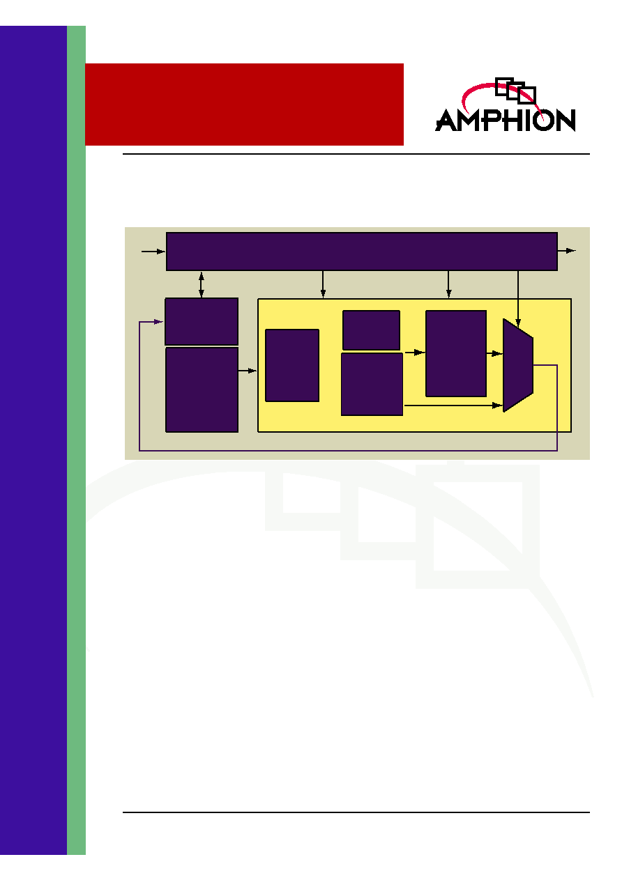
Figure 1: CS2411 Block Diagram
Mux
Y
X
Processing Unit
Radix-4/
Selectable
Butterfly
Complex
Number
Multiplier
Twiddle
LUT
Radix-4
Butterfly
Memory
Controller
1024-word
dual-port
memory
I/O interface and transform control
FEATURES
On-line programmable FFT/IFFT core
13-bit complex input/output in two's
complement format (26-bit complex word)
13-bit twiddle factors generated inside the
core
16-bit fixed-point internal arithmetic operation
Programmable shift down control
Mixed radix-4 - radix-16 architecture
Transform performed in four computation
passes with zero-waiting
Simultaneous loading/downloading
supported
Both input and output in normal order
No external memory required
Optimized for both ASIC and FPGA
technologies with the same functionality
Fully synchronous design
KEY METRICS
Logic Area:
34K gates
Memory Area:
51K RAM
Input Clock:
108 MHz
APPLICATIONS
Communications modulation schemes
Image processing
Atmospheric imaging
Spectral representation
2
CS2411
1024 Point FFT/IFFT
FAST FOURIER TRANSFORM
FFT (Fast Fourier Transform) and IFFT (Inverse Fast Fourier
Transform) are algorithms computing 2
p
-point discrete
Fourier transform and inverse discrete Fourier transform, as
defined below.
FFT: [1]
IFFT:
[2]
Where N=2
P
and
.
The computational complexity of FFT and IFFT is
proportional to Nlog
R
N, where R is the radix base on which
FFT/IFFT is performed. The higher the radix, the less number
of multiplication is required, however the more simultaneous
multiple data access is required which causes the circuits to be
more complicated. The radix-4 algorithm offers a balance
between the computational and circuit complexity and is often
used in construction of higher radix FFT computation units
when designing high performance FFT/IFFT hardware.
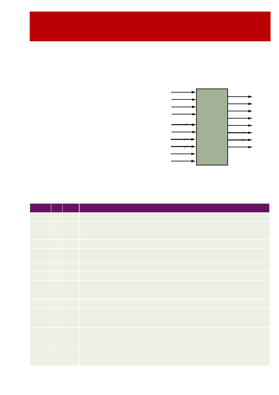
CS2411 SYMBOL
AND PIN DESCRIPTION
Table 1 describes input and output ports (shown graphically
in Figure 2) of the CS2411 1024-point FFT/IFFT core. Unless
otherwise stated, all signals are active high and bit(0) is the
least significant bit.
Figure 2: CS2411 Symbol
Y k
( )
X n
( )
n
0
=
N 1
�
W
nk
�
N
=
, k=0, 1, 3, ...N-1
Y k
( )
1
N
----
X n
( )
n
0
=
N 1
�
W
nk
N
=
, k=0, 1, 3, ...N-+1
e
j2
�
N
/
CS2411
1024-pt
FFT/IFFT
Ylm
YRe
YOV
Xlm
CLK
NotRST
STE*
YEnab
13
XRe
13
XBS
SDC
3
IFFT
CLR
13
13
XBIP
Busy
YBS
Done
YAV
Table 1: CS2411 - 1024 Point FFT / IFFT Interface Signal Definitions
Name
I/O Width
Description
CLK
I
1
Clock signal, rising edge active
NotRST
I
1
Asynchronous global reset signal, active LOW
CLR
I
1
Clear (synchronous reset) and programming signal, active HIGH
IFFT
I
1
Programming signal specifying the transform type, loaded when CLR is active
SDC
I
3
Programming signal specifying the number of bits for the additional scaling down operation, loaded
when CLR is active
XRe
I
13
Real component of input data X, in two's complement format
XIm
I
13
Imaginary component of input data X, in two's complement format
XBS
I
1
Input data X block start signal, active HIGH, associated with the first input data of the 1024-point
block. The remaining data of the 1024-point data block is loaded into the core in the following clock
cycles in the natural order.
YEnab
I
1
Output data Y enable control, active HIGH
STE*
I
1
Scan Test Enable Signal � ASIC version only
During scan testing the memory block needs to be bypassed to allow the scan test to be performed.
During test STE is set HIGH and the memory is bypassed. During normal operation STE is set LOW.
XBIP
O
1
Output signal indicating loading X is in Progress. XBIP goes to HIGH the next clock cycle when XBS
is active and returns to LOW when the last data of the 1024-point block is loaded into the core. XBS is
ignored when it is HIGH.
Busy
O
1
Output signal indicating the transform in progress (busy). It goes to HIGH the next clock cycle when
the last data of the 1024-point block is loaded into the core and returns to LOW when the core is ready
to accept the next input data block. XBS is ignored when it is HIGH.

3
TM
FUNCTIONAL DESCRIPTION
The CS2411 performs a mixed decimation in frequency (DIF),
radix-4, forward or inverse Fast Fourier Transforms on a 1024-
point complex data block. The transform is scheduled in four
computation passes. Data is loaded into the core in normal
sequential (natural) order. The transform result comes out
from the core in the natural order also. The core is on-line
programmable on the transform type and scaling down
control. The input and output data and the twiddle factor
wordlengths have been chosen such that it can be used in a
wide range of applications such as audio, video and
communications.
The core computes the transform using fixed-point arithmetic
with programmable shift down control on each computation
passes to handle the possible wordlength growth and
overflow in the transform. This achieves the maximal
accuracy possible while maintaining the desired dynamic
range for the output. The core is a synchronous design with all
the flip-flops being triggered at the rising edge of the clock
signal CLK.
PROGRAMMING THE CORE
Programming CS2411 is performed when the core is
synchronously reset. This is done through asserting signal
CLR and applying appropriate signals to the input ports IFFT
and SDC. Port IFFT specifies the transform type i.e. FFT/IFFT
Table 2 lists the FFT/IFFT value for programming the core to
appropriate transform type.
The core performs 4-bit unconditional shifting down on the
internal data during the 1024-point transform. However,
theoretically the 1024-point FFT may have up to a total of 11-
bits word growth. The CS2411 core can perform up to 4-bit
unconditional shifting down and 7-bit controlled shifting
down operation to avoid possible overflow and also to allow
the transform gain to be controlled. This is programmed
through port SDC. The total number of shift down bits
decides the transform scaling down factor. Table 3 lists the
SDC values for programming the scaling factor.
Done
O
1
Output signal indicating the transform result is available. It goes to HIGH when the core is ready to
output transform result and returns to LOW when YEnab is asserted to download the result.
YBS
O
1
Output data Y block start signal, active HIGH, asserted when the first data of the 1024-point trans-
formed block is available on the output port. The remaining data of the 1024-point transform result is
available at the output of the core in the following clock cycles in natural order.
YAV
O
1
Output data Y available indicator, active HIGH, asserted with valid data of the 1024-point transform
result
YRe
O
13
Real component of output data Y, in two's complement format, valid only when YAV is HIGH
YIm
O
13
Imaginary component of output data Y, in two's complement format, valid only when YAV is HIGH
YOV
O
1
Output data Y overflow signal, active HIGH, asserted when overflow occurs when the transform is
performed. It is reset when a new transform starts and is associated with the 1024-point block.
Table 1: CS2411 - 1024 Point FFT / IFFT Interface Signal Definitions
Name
I/O Width
Description
Table 2: Programming Transform Type
Port IFFT
Transform Type
0
FFT
1
IFFT
Table 3: Programming Scaling Factor
Port SDC
Fixed
Shifting
(Bits)
Additional
Shifting
(Bits)
Scaling
Factor
(2
-(7+SDC)
)
000
4
0
1/16
001
4
1
1/32
010
4
2
1/64
011
4
3
1/128
100
4
4
1/256
101
4
5
1/512
110
4
6
1/1024
111
4
7
1/2048

4
CS2411
1024 Point FFT/IFFT
After the global asynchronous reset signal, RST is applied, the
core is reset to the default mode: 1024-point FFT without the
additional shifting operation. Programming the core can be
performed at any time subsequently. The programming
signals are valid only when CLR is asserted. This is illustrated
in Figure 3. It is noted that when CLR is applied the core is
reset as well.
Figure 3: Configuration Timing
INPUT AND OUTPUT DATA FORMAT
The input complex number data is represented by 13-bit real
and imaginary components, namely XRe and XIm, in the
two's complement format. The input data is loaded into the
core in the normal order, i.e., X(0) enters the core first,
followed by X(1) in the next clock cycle, and then X(2) in the
following cycle, etc. In total it takes 1024 clock cycles for a data
block to enter the core for FFT/IFFT processing.
The transform data is represented by complex numbers
which consist of a 13-bit real component YRe and a 13-bit
imaginary component YIm both in the two's complement
format. The output data is burst out from the core when the
transform has been performed to the stage that allows the
result to be output and the output port is enabled. The result
from the core is also in the normal order, i.e., Y(0) first,
followed by Y(1), Y(2) and so on.
TRANSFORM COMPUTATION
The transform is scheduled to complete in four passes. In each
pass the controller fetches the intermediate data from the
internal dual port memory, sends it to the processing unit,
fetches the computation results from the processing unit and
writes the result back to memory for the next pass or for the
output. The CS2411 employs a Cooley-Tukey radix-4
decimation-in-frequency (DIF) to compute the FFT/IFFT. This
algorithm requires the calculation of radix-4 butterflies and
twiddle multiplications in multiple passes. Theoretically the
intermediate result value of a radix-4 butterfly with twiddle
operation may grow by a factor of up to 5.657. This represents
up to three-bit wordlength growth. In the last pass radix-16
operations are effectively performed. This will possibly result
in additional one bit wordlength growth. The core performs
one bit right-shift on the intermediate result unconditionally
in the four passes. A rounding technique is employed to
achieve the maximal computation accuracy possible. When
the intermediate value is derived from the twiddle
multiplication result, or the input to the butterfly is scaled
down, round-to-the-nearest operation is performed. This
gives the maximal computation accuracy possible for the
given wordlength.
The CS2411 core performs scaling down operation by right
shifting the intermediate result in the four passes, according to
the scaling down control programmed. Table 5 lists the
relationship between the programming input signal SDC and
the number of scaling down bits performed in the four passes.
It is noted that there is no overflow in the computation when
the total number of shifting bits is equal to 11 bits.
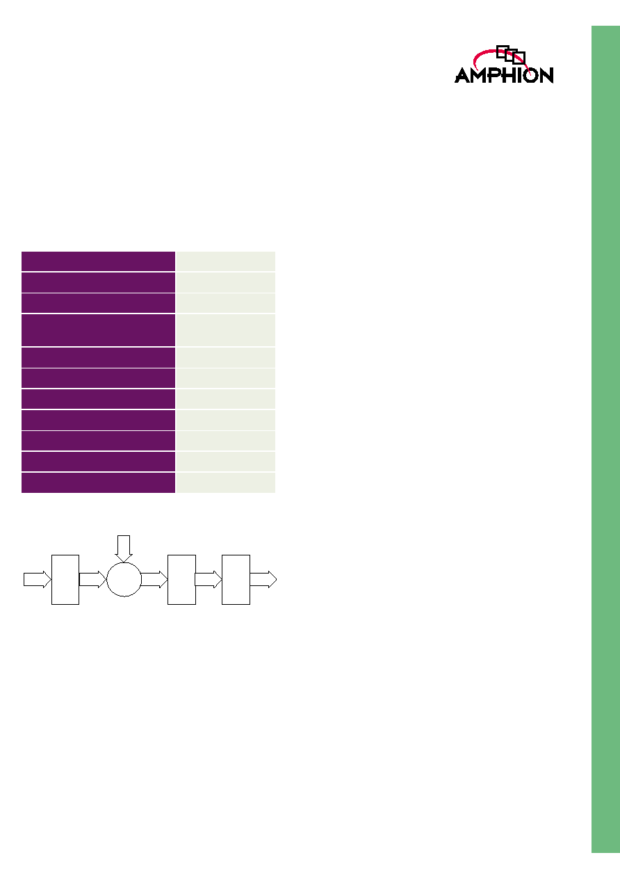
FIXED WORD LENGTH AND ACCURACY
The CS2411 core uses fixed-point arithmetic to perform the
transform. The twiddle factors (Sine and Cosine values),
which are generated by the core internally, have 13-bit
accuracy. At the end of each computation pass, the result is
rounded to 13 bits. Figure 4 illustrates the word lengths at
various computation stages in the CS2411 core.
The rounding technique is employed to achieve the maximal
computation accuracy possible for the given word lengths.
When the intermediate value is derived from the twiddle
multiplication result, the output from the butterflies is scaled
down, or the intermediate result is right shifted, the core
performs the round-to-the-nearest operation to keep the loss
of accuracy minimal.
CLK
RST
CLR
IFFT
SDC
Table 4: Transform Operations in Each Pass
Transform
Size
Pass 1
Pass 2
Pass 3
Pass 4
1024-point
Radix-4
Radix-4
Radix-4
Radix-16
Table 5: Number of Right Shifting Bits in Each Pass
SDC
Pass 1 Pass 2 Pass 3 Pass 4
Total
000
1
1
1
1
4
001
2
1
1
1
5
010
2
2
1
1
6
011
2
2
1
1
7
100
3
2
2
1
8
101
3
2
2
2
9
110
3
2
2
3
10
111
3
2
2
4
11
5
TM
Table 6 gives the simulation results on the transform accuracy
of CS2411 core. These results are obtained by applying 64
blocks of 13-bit random input data to the core and the scaling
down control is set such that there is just no overflow in the
computation. For example, the output magnitude is
maximized while no overflow occurs. The 13-bit output data
from the core is compared with the result of double precision
FFT model. The error is measured in terms of the output LSB
weight. It is noted that when overflow occurs the transform
accuracy will be decreased severely.
Figure 4: Word Length In Arithmetic Operations
LOADING INPUT AND DOWNLOADING
RESULT
Loading the input data is performed under the control of XBS
signal. The XBS signal should be asserted when the output
signal XBIP and BUSY are LOW. It indicates the first data of
the 1024-point data block. The data is clocked in on the clock
rising edge. The remaining data of the 1024-point data block is
loaded in on the rising edge of the clock in natural order
successively.
When the core starts to load a 1024-point data block, signals
XBIP and BUSY are asserted to indicate that loading of a data
block is in progress. Signal XBS will be ignored when XBIP is
HIGH. When the last data of the block is loaded into the core,
XBIP signal returns to LOW and signal BUSY stays HIGH to
indicate the transform computation is in progress. Signal XBS
is still ignored in this case until Busy returns to LOW.
The CS2411 core starts the transform prior to the completion
of loading the 1024-point data block when the required data
has been loaded, i.e., the input data loading is overlapped
with the first computation pass. This compensates the latency
introduced by the pipelined computation units so that the
input data loading and the four computation passes can be
completed in 5*1024 clock cycles. Signal Done goes to HIGH
when the transform result is available (after 5093 cycles).
Downloading of the transform result is started by asserting
the input signal YEnab when Done is HIGH. Signal Done
returns to LOW when downloading is started. The first
sample of the transform result comes out from the core in the
natural order two clock cycles later after YEnab is asserted.
Output signal YAV is asserted when the data on port YRe and
YIm are valid and output signal YBS is asserted when the first
sample of the 1024-point result is on the output port. The
output data burst out from the core in 1024 clock cycles.
Downloading the result can be overlapped with the 4th
computation pass to achieve 5*1024 clock cycles operation, if
input signal YEnab is asserted as soon as the output signal
Done goes to HIGH. The loading of the next data block can be
started as soon as output signal Busy is de-asserted. Figure 5
shows the functional timing for the 5*1024 clock cycle I/O and
transform operation. It is noted that the input signal YEnab
can be constantly asserted and if so the transform result will
be automatically downloaded when available.
It should be noted that the core waits for YEnab being asserted
when signal Done goes HIGH to start the downloading
process, allowing the user to control the transform data flow.
The system clock rate is not restricted to the 5*1024 cycles and
can be any rate higher than 5X the data rate. In this case if the
downloading result has been completed but loading the next
block is not started, signal Done will go to HIGH again to
indicate that the transform result is still available in the
internal memory and can be downloaded again. This feature
can be utilized in C-OFDM modulation systems to perform
the guard interval insertion. Figure 6 shows the operating
flowchart for the CS2411 core.
Table 6: Simulation Results of Transform Accuracy
Transform Size
1024-point
SDC setting
3
Scaling Factor
1/(2^7)
Number of complex data
samples compared
64K
Maximal output Magnitude
2624
Maximal Error (Re)
7
Maximal Error (Imag)
7
Average Absolute Output
472.134
Average Absolute Error
0.851654
Mean Square Error
1.3474
Average SNR
54.876 dB
Shift
Round
Overflow
Detect
Radix-4
Butterfly
Radix-4
Butterfly
13 bits
13 bits
13 bits
15 bits
16 bits
twiddle
Multiply
17 bits