
TM
Virtual Components for the Converging World
Amphion continues to expand its family of application-specific cores
1
See http://www.amphion.com for a current list of products
CS2412
1024-Point Pipelined FFT/IFFT
Preliminary Datasheet
The CS2412 is an online programmable, pipelined architecture 1024-point FFT/IFFT core. It is capable of
processing continuous data streams with high data throughput rate of up to 50 Msamples/Sec. This highly
integrated application specific silicon core is the pipelined version of CS2411 and is available in both ASIC and
FPGA versions that have been handcrafted by Amphion for maximum performance while minimizing power
consumption and silicon area.
Figure 1: CS2412 Architecture
(768+
1024)
32-bit
word
Input
Buffer
Radix-4
Butterfly &
Twiddle
Multiplication
(192+
256)
32-bit
word
Input
Buffer
Radix-4
Butterfly &
Twiddle
Multiplication
Radix-4
Butterfly &
Twiddle
Multiplication
Radix-4
Butterfly &
Twiddle
Multiplication
Radix-4
Butterfly
(48+
64)
32-bit
word
Buffer
(12+
16)
32-bit
word
Buffer
(3+4)
32-bit
word
Buffer
1024
32-bit
word
Re-order
Buffer
Control Logic
FEATURES
On-line programmable FFT/IFFT core
Pipelined architecture
16-bit complex input/output in two's
complement format (32-bit complex word)
16-bit twiddle factors generated inside the
core
18-bit internal accuracy
Programmable shift down control
Radix-4 architecture
Simultaneous loading/downloading
supported
Both input and output in normal order
No external memory required
Optimized for both ASIC and FPGA
technologies with the same functionality
Fully synchronous design
APPLICATIONS
Communications modulation schemes
Image processing
Atmospheric imaging
Spectral representation

2
CS2412
1024-Point Pipelined FFT/IFFT
FAST FOURIER TRANSFORM
FFT (Fast Fourier Transform) and IFFT (Inverse Fast Fourier
Transform) are algorithms computing 2
P
-point discrete
Fourier transform and inverse discrete Fourier transform, as
defined below
FFT
, k = 0, 1, 2... N-1
[1]
IFFT:
, k = 0, 1, 2... N-1
[2]
Where N=2
p
and W
N
= e
-j2
/N
The computational complexity of FFT and IFFT is
proportional to Nlog
R
N, where R is the radix base on which
FFT/IFFT is performed. The higher the radix, the less number
of multiplication is required, however the more simultaneous
multiple data access is required which causes the circuits to be
more complicated. The radix-4 algorithm offers a balance
between the computational and circuit complexity and is often
used in construction of higher radix FFT computation units
when designing high performance FFT/IFFT hardware.
CS2412 SYMBOL
AND PIN DESCRIPTION
Table 1 describes input and output ports (shown graphically
in Figure 2) of the CS2412 1024-point FFT/IFFT core. Unless
otherwise stated, all signals are active high and bit(0) is the
least significant bit.
Figure 2: CS2412 Symbol
Y k
( )
X n
( )W
nk
�
N
n
0
=
N 1
�
=
Y k
( )
1
N
----
=
X n
( )W
nk
N
n
0
=
N 1
�
CS2412
1024-pt
FFT/IFFT
Ylm
YRe
YOV
Xlm
CLK
NotRST
16
XRe
16
XBS
SDC
3
TType
16
16
XBIP
YBS
YAV
YSDC
3
Table 1: CS2412 1024-Point FFT/IFFT Interface Signal Definitions
Name
I/O
Width
Description
CLK
I
1
Data clock signal, rising edge active
NotRST
I
1
Asynchronous global reset signal, active LOW
TType
I
1
Static signal specifying the transform type,
0: FFT,
1: IFFT
SDC
I
3
Input signal specifying the number of bits for the additional scaling down operation, loaded
when XBS is active and associated with the 1024-point block indicated by XBS.
Xre
I
16
Real component of input data X, in two's complement format
Xim
I
16
Imaginary component of input data X, in two's complement format
XBS
I
1
Input data X block start signal, active HIGH, associated with the first input data of the N-point
block. The remaining N-1 data of the N-point data block are loaded into the core in the follow-
ing N-1 data clock cycles in the natural order.
XBIP
O
1
Output signal indicating loading X is in Progress. XBIP goes to HIGH the next clock cycle
when XBS is active and returns to LOW when the last data of the N-point block is loaded into
the core. XBS is ignored when it is HIGH.
YBS
O
1
Output data Y block start signal, active HIGH, asserted when the first data of the N-point
transformed block is on the output port. The remaining N-1 data of the N-point transform
result come out of the core in the following N-1 clock cycles in the natural order.
3
TM
FUNCTIONAL DESCRIPTION
The CS2412 performs decimation in frequency (DIF) radix-4
forward or inverse Fast Fourier Transforms on complex data.
Data is loaded into its workspace in normal sequential
(natural) order. The transformed data is returned in normal
sequential order. It performs 1024-point FFT/IFFT using the
following equations:
FFT:
, k = 0, 1, 2 ... N-1
[3]
IFFT:
, k = 0, 1, 2 ... N-1
[4]
Where N is equal to 1024, SDC is the scaling down control
signal, X(n) is the complex input data and Y(k) the complex
output data. Both the real and imaginary components of input
X(n) and output Y(k) are 16-bit numbers in two's complement
format.
The CS2412 achieves high data throughput rates of up to 50
Msamples/Sec by employing a pipelined architecture with
fixed-point arithmetic operations and pre-scaling strategy to
handle possible overflow in computation. The core has 4-bit
unconditional scaling down operations and 7-bit controlled
scaling down operations specified by input signal SDC, giving
the user the necessary gain control required in a specific
application. The CS2412 core uses radix-4 decimation in
frequency (DIF) algorithm to perform the transform. It
consists of five radix-4 pipelined stages with reshuffle buffers
between stages and is capable of processing continuous data
stream. Both the input and output are in the normal order (the
ordinary time order).
The Selection of transform (FFT/IFFT) is controlled by a static
signal. However, the scaling down control is applied on a
block-by-block basis. The core detects possible overflow
during computation and saturates overflow data accordingly.
In order to minimize the device size, CS2412 uses a 2 x clock
internally. For example, the input data is clocked in using the
data clock while the core operates on the 2 x clock. The output
data is also clocked out on the 2xclock although it changes
only on every 2 cycles of the 2 x clock. When implemented on
FPGA devices, The 2 x clock is generated by the on-chip PLL
of Apex 20KE device or DLL of Virtex devices.
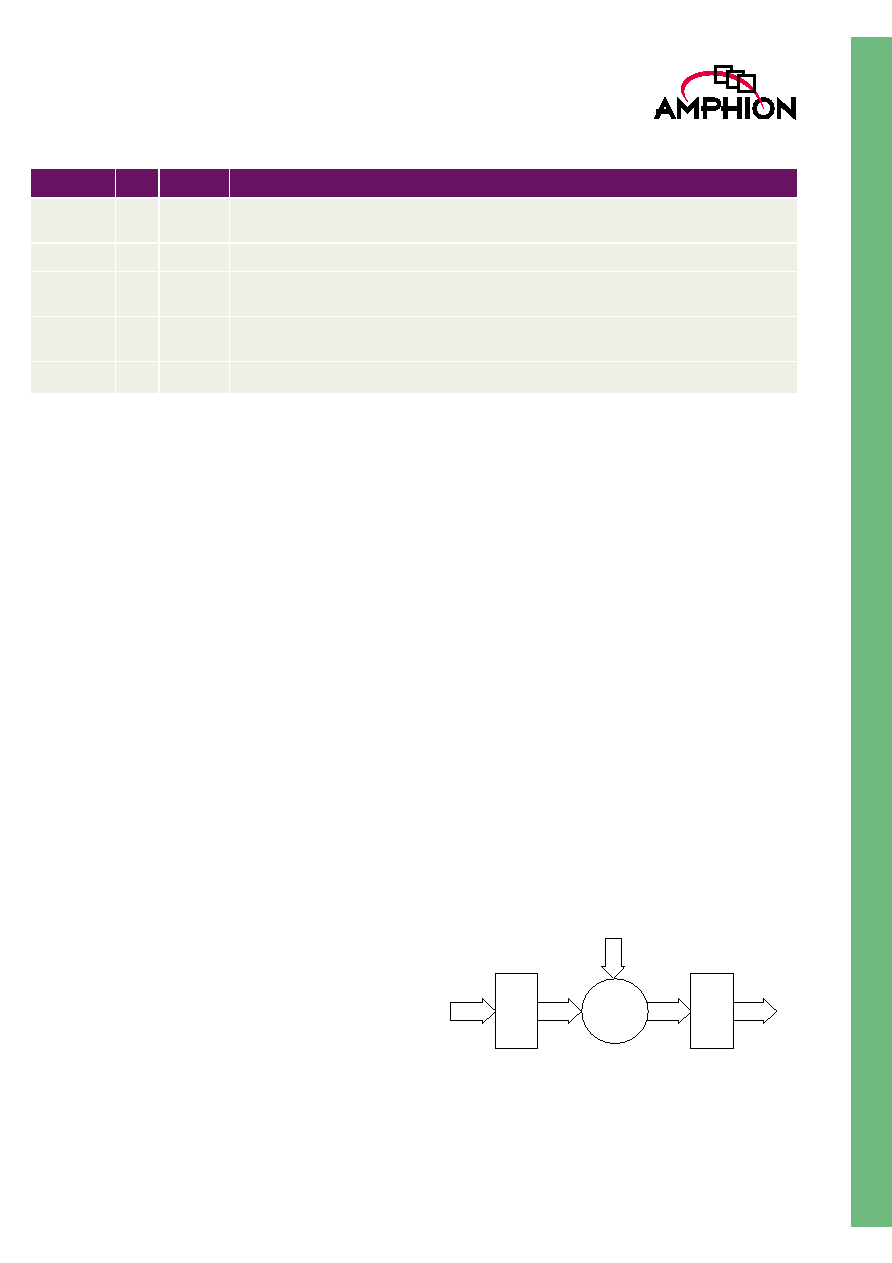
WORD LENGTH
The internal wordlength of each radix-4 operation of CS2412
is specified by Figure 3. The intermediate data stored in the
reshuffle buffers are 16-bit wide (32 bits for complex
numbers). The wordlength grows to 18 bits after the radix-4
butterfly. The twiddle multiplier takes the 18-bit butterfly
output and 16-bit twiddle factors, generating 34-bit product.
The product is then scaled and rounded to 16 bits for the next
stage radix-4 operation.
Figure 3: Wordlength Specification
YAV
O
1
Output data Y available indicator, active HIGH, asserted with all data of the N-point transform
result
YRe
O
16
Real component of output data Y, in two's complement format, valid only when YAV is HIGH
YIm
O
16
Imaginary component of output data Y, in two's complement format, valid only when YAV is
HIGH
YOV
O
1
Output data Y overflow signal, active HIGH, asserted when overflow occurs during the trans-
form of the output data block.
YSDC
O
3
Output signal indicating the SDC of the output data block
Table 1: CS2412 1024-Point FFT/IFFT Interface Signal Definitions
Name
I/O
Width
Description
Y k
( )
1
2
4 SDC
+
--------------------
X n
( )
n
0
=
N 1
�
W
nk
�
N
=
Y k
( )
1
2
4 SDC
+
--------------------
X n
( )
n
0
=
N 1
�
W
nk
N
=
16 bits
18 bits
34 bits
16 bits Twiddle factor
Radix-4
Butterfly
16 bits
Twiddle
Multiply
Scaling &
Rounding
Radix-4
Butterfly

4
CS2412
1024-Point Pipelined FFT/IFFT
FUNCTIONAL OPERATION
The core is capable of processing continuous data stream.
Loading the input data is performed under the control of
signal XBS. Signal XBS is asserted when the output signal
XBIP is de-asserted. It indicates the first data of the 1024-point
data block and the data is clocked in on the clock rising edge.
The rest of the 1023-points of data are loaded in the successive
1023 clock cycles in the natural order. When the last data is
loaded signal XBIP returns to LOW. Loading of the next data
block can be started by asserting XBS at any time from the
next clock cycle after XBIP returns to LOW.
Signal YBS is asserted, when the first of the result data
appears on the output port. The rest of the result data will be
continuously clocked out in the following 1023 clock cycles.
Signal YAV will be asserted during the period of the result
being output. Figure 4 illustrates the functional timing of the
I / O signals.
Figure 4: Input/Output Functional Timing
CLK
XBS
0
1
2
1023
XRE
XIM
XBIP
0
1
n-1
n
n+1
n+2
n+3
0
1
2
3
YRE
YIM
YBS
YAV
2040 cycles
SDC
YSDC
5
TM
SHIFTING CONTROL
The kernel operation for 1024-point transform consists of
radix-4 butterfly followed by a twiddle multiplication.
Theoretically in the worst case the result value may grow by a
factor of up to 5.657 in the first stage. This occurs when the
four input data to the radix-4 computation have the maximal
absolute value and the twiddle angle is
/
4
. The final result
reaching stage 5 may grow by a factor of up to 1303.793. This
represents a possible wordlength growth of 11 bits. As the
output is 16-bit value and fixed-point arithmetic is employed
in the core, it is necessary to be able to scale the result to avoid
overflow while still obtaining a good dynamic range.
Since the input word length is 16 bits and the output 16 bits,
zero bit growth can be allowed. Thus, the megafunction must
have the capability of up to 11-bit right shifting of the internal
result to enable overflow to be avoided. The total of 11 bit
scaling down operation is assigned to each stage according to
Table 2. When SDC is set to the maximal value, there will be
no overflow for any input data.
The first 4-bits of shift control are mandatory. The remaining
7-bits are applied at the discretion of the user under the
control of SDC.
COMPUTATION ACCURACY
A rounding technique is employed to achieve the maximal
computation accuracy possible for the given word lengths.
The core performs the round-to-the-nearest operation to keep
the loss in accuracy minimal. When the intermediate value, for
instance from the twiddle multiplication result, is required to
scale down, the most significant bit of the portion to be
rounded off is added to the word which remains. This is a
compromise between true rounding and truncation.
Compared with the technique that unconditionally sets the
bottom bit to '1', the partial rounding scheme achieves better
accuracy and guarantees to generate an all-zero output block
for an all-zero input block.
CS2412 detects overflow at each computation stage and uses
the following procedure to saturate output overflow samples:
If (X >= 32768) X = 32767;
If (X <= -32768) X = -32767;
The bit accurate C model provided checks of the output error
with respect to SDC signal. Table 3 represents the output error
with respect to SDC signal.
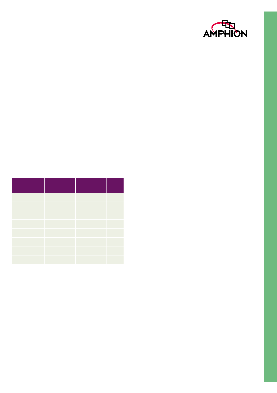
Table 2: Number of Shifting Bits in Each Stage
SDC Stage
1
Stage
2
Stage
3
Stage
4
Stage
5
Total
000
1
1
1
1
0
4
001
2
1
1
1
0
5
010
2
2
1
1
0
6
011
3
2
1
1
0
7
100
3
2
2
1
0
8
101
3
2
2
1
1
9
110
3
2
2
2
1
10
111
3
2
2
2
2
11