 | –≠–ª–µ–∫—Ç—Ä–æ–Ω–Ω—ã–π –∫–æ–º–ø–æ–Ω–µ–Ω—Ç: CS2420XV | –°–∫–∞—á–∞—Ç—å:  PDF PDF  ZIP ZIP |

TM
Virtual Components for the Converging World
Amphion continues to expand its family of application-specific cores
1
See http://www.amphion.com for a current list of products
CS2420
2048/4096/8192 Point FFT/IFFT
The CS2420 is an online programmable 2048 - 8192-point FFT/IFFT core. It is based on the radix-4 algorithm and
performs 2048-point to 8192-point FFT/IFFT computation in three computation passes. A block diagram of the
core is shown in.
Figure 1: CS2420 Block Diagram
I/O Interface and Transform Control
Memory
Controller
4096x32
Dual-port
Memory
Processing Unit 1
Radix-4
Butterfly
X
Y
Processing Unit 2
4096x32
Dual-port
Memory
Radix-2/
Radix-4
Butterfly
Complex
Number
Multiplier
8/16-point
Twiddle
LUT
2048, 4096 &
8192-point
Twiddle Factor
generator
Complex
Number
Multiplier
Radix-2
Butterfly
FEATURES
On-line programmable FFT/IFFT core
16-bit complex input/output in two's
complement format (32-bit complex word)
16-bit twiddle factors generated inside the
core
18-bit internal accuracy
Programmable shift down control
Mixed radix-8/radix-16/radix-32 architecture
Simultaneous loading/downloading
supported
Both input and output in normal order
No external memory required
Optimized for both ASIC and FPGA
technologies with the same functionality
KEY METRICS
Logic:
59k gates
Memory:
<3.9mm
2
Total area:
<4.5mm
2
See Table 8 - 10 for more details
APPLICATIONS
Image processing
Atmospheric imaging
Spectral representation
OFDM modulation scheme for DVB-T (Ref:
ETS 300 744)

2
CS2420
2048/4096/8192 Point FFT/IFFT
CS2420 I/O DESCRIPTION
Table 1 describes the input/output ports (shown graphically in
Figure 2) for the CS2420 FFT/IFFT core. Unless otherwise
stated all signals are active High, and bit (0) is the least
significant bit.
Figure 2: CS2420 Symbol
CS2420
2048-
8192pt
FFT/IFFT
CLK
NotRST
CLR
IFFT
CFG
2
XRe
16
XBS
XIm
16
XBIP
YRe
16
YIm
16
YBS
YAV
YOV
Busy
Done
YEnab
SDC
3
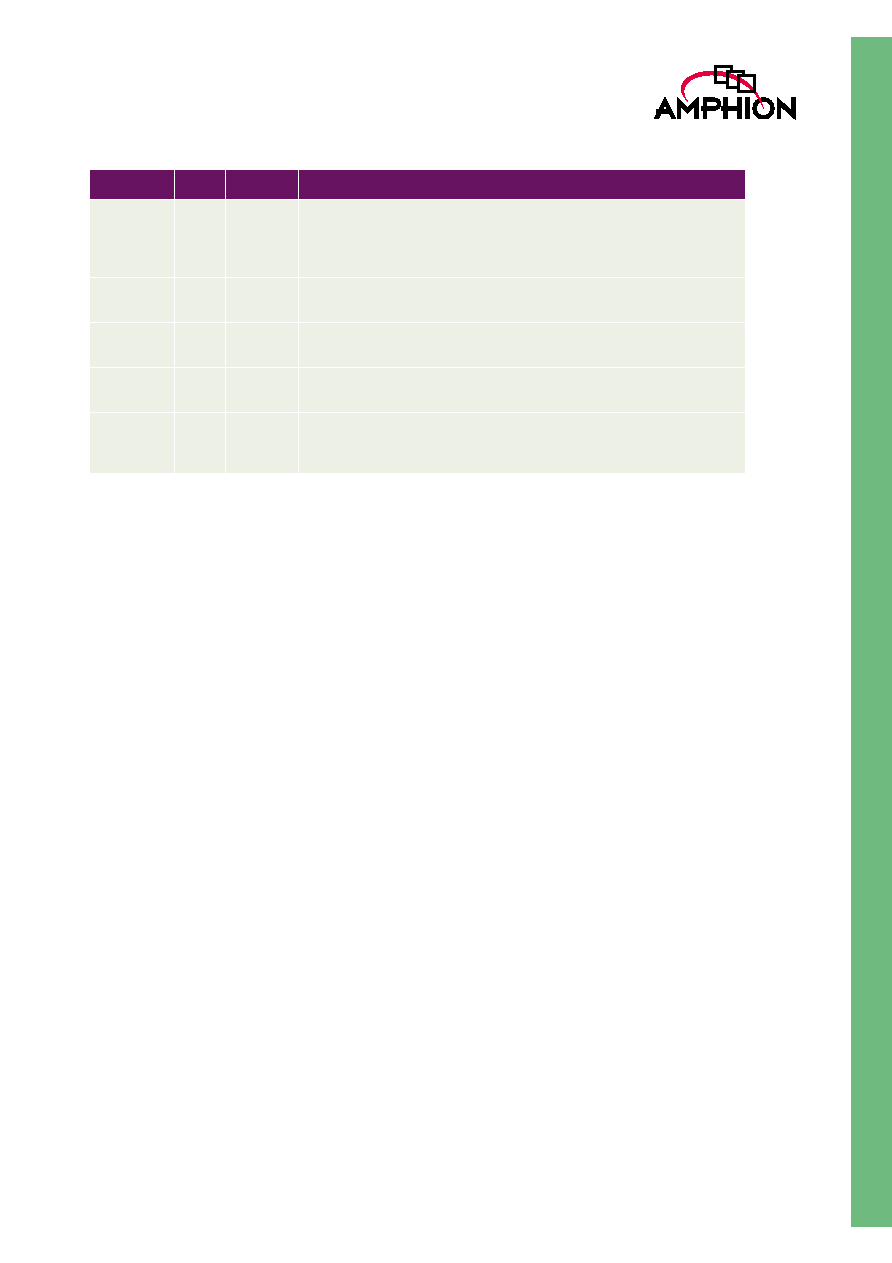
Table 1: I/O Description for the CS2420
Name
I/O
Width
Description
CLK
I
1
Clock signal, rising edge active
NotRST
I
1
Asynchronous global reset signal, active LOW
CLR
I
1
Clear (synchronous reset) and programming signal, active HIGH
IFFT
I
1
Programming signal specifying the transform type, loaded when CLR is
active. 1:IFFT; 0:FFT
CFG
I
2
Programming signal specifying the transform size, loaded when CLR is
active. 01:2k; 10:4k; 11:8k
SDC
I
3
Programming signal specifying the number of bits for the additional scal-
ing down operation, loaded when CLR is active
XRe
I
16
Real component of input data X, in two's complement format
XIm
I
16
Imaginary component of input data X, in two's complement format
XBS
I
1
Input data X block start signal, active HIGH, associated with the first
input data of the N-point block. The remaining N-1 data of the N-point
data block are loaded into the core in the following N-1 clock cycles in
the natural order.
YEnab
I
1
Output data Y enable control, active HIGH
XBIP
O
1
Output signal indicating loading X is in Progress. XBIP goes to HIGH the
next clock cycle when XBS is active and returns to LOW when the last
data of the N-point block is loaded into the core. XBS is ignored when it
is HIGH.
Busy
O
1
Output signal indicating the transform in progress (busy). It goes to
HIGH the next clock cycle when XBS is active and returns to LOW when
the core is ready to accept the next input data block. XBS is ignored
when it is HIGH.
Done
O
1
Output signal indicating the transform result is available. It goes to HIGH
when the core is ready to output transform result and returns to LOW
when YEnab is asserted to download the result.
3
TM
GENERAL DESCRIPTION
The CS2420 performs N-point FFT/IFFT following the
equations below:
Where N is 2048, 4096 or 8192, SDC is the scaling down
control signal, X(n) is the complex input data and Y(k) the
complex output data. Both the real and imaginary
components of input X(n) and output Y(k) are 16-bit two's
complement numbers.
In order to achieve highest data throughput rate possible,
CS2420 employs fixed-point arithmetic operations and pre-
scaling strategy to handle possible overflow in computation.
The core has 7-bit unconditional scaling down operations and
7-bit controlled scaling down operations specified by input
signal SDC, giving the user the necessary gain control means
required in the application.
CS2420 employs two computation units in pipeline to perform
the transform in three passes, using a mixed radix-8/radix-16
and radix-32 algorithm. Processing unit 1 consists of a radix-4
butterfly, an 8-point/16-point twiddle LUT, a complex number
multiplier and a selectable radix-2/radix-4 butterfly. It
performs one 16-point transform or two 8-point transforms in
16 clock cycles according to the control signals from the
transform controller. Processing unit 2 consists of a 2048/4092/
8192-point twiddle factor generator, a complex number
multiplier and a radix-2 butterfly. In the first two passes of the
computation, it takes the output of processing unit 1 and
performs twiddle operation. In the last pass, it either directs
the output of processing unit 1 to the controller when the core
is in 2048- or 4096-point transform mode or performs 32-point
twiddle and radix-2 operations when the core is in 8192-point
mode.
Programming CS2420 is performed when the synchronous
reset signal CLR is active. The programming signals, namely,
IFFT, CFG and SDC, are loaded into the core. These set up the
transform type, transform size and scaling down controls.
CS2420 performs the three computation passes continuously
in a pipelined manner without wasting any clock cycle, due to
the fixed-point arithmetic and pre-scaling strategy used. The
core can perform the transform and loading input data/
downloading transform result with a 4x clock. For example,
an 8192-point transform with data/IO can be performed with
32768 clock cycles.
The scaling down operation is spread into various computing
passes and computation units. The two processing units use
18-bit arithmetic operations and detect the possible overflow
in computation. When overflow occurs, the processing units
flag it to the controller and saturate the overflow results on the
fly.
The core has separate I/O indicator and control signals to
support simultaneous or separate loading input data and
downloading the transform result. The input data is burst in
to and the transformed result is burst out from CS2420 on
block-by-block basis.
YBS
O
1
Output data Y block start signal, active HIGH, asserted when the first
data of the N-point transformed block is on the output port. The remain-
ing N-1 data of the N-point transform result come out of the core in the
following N-1 clock cycles in the natural order.
YAV
O
1
Output data Y available indicator, active HIGH, asserted with every data
of the N-point transform result
YRe
O
16
Real component of output data Y, in two's complement format, valid only
when YAV is HIGH
YIm
O
16
Imaginary component of output data Y, in two's complement format,
valid only when YAV is HIGH
YOV
O
1
Output data Y overflow signal, active HIGH, asserted when overflow
occurs when the transform is performed. It is reset when a new trans-
form starts and is associated with the N-point block.
Table 1: I/O Description for the CS2420
Name
I/O
Width
Description
FFT: Y k
( )
1
2
7 SDC
+
--------------------
X n
( )
W
N
nk
≠
,k=0, 1, 2,.. [1]
n
0
=
N 1
≠
=
IFFT Y k
( )
1
2
7 SDC
+
--------------------
X n
( )
W
N
nk
,k=0, 1, 2, [2]
n
0
=
N 1
≠
=

4
CS2420
2048/4096/8192 Point FFT/IFFT
FUNCTIONAL DESCRIPTION
GENERAL
CS2420 performs a mixed decimation in frequency (DIF),
radix-8, radix-16 and radix-32, forward or inverse Fast Fourier
Transform on 2048-point, 4096-point or 8192-point complex
data block. The transform is scheduled in three computation
passes. Data is loaded into the core in normal sequential
(natural) order. The transform result comes out from the core
also in the natural order.
The core is on-line programmable on the transform type,
transform size and scaling down control. The input and
output data and the twiddle factor wordlengths are selected
such that it can be used in a wide range of applications.
The core computes the transform using fixed-point arithmetic
with programmable shift down control on each computation
pass to handle the possible wordlength growth and overflow
in the transform. This achieves the maximal accuracy possible
while maintaining the desired dynamic range for the output.
The internal 8K 32-bit word dual port memory is organised in
two banks with 4K words each. In 2048-point and 4096-point
transform mode, only one bank is enabled. This is to improve
power consumption of the core when it is operating for the
smaller transform size.
The core is a synchronous design with all the flip-flops being
triggered at the rising edge of the clock signal CLK.
PROGRAMMING THE CORE
Programming CS2420 is performed when the core is
synchronously reset. This is done through asserting signal
CLR and applying appropriate values to input ports CFG,
IFFT and SDC.
Port CFG and IFFT specify the transform size and transform
type. Table 2 lists the CFG and IFFT value for programming
the core to different transform sizes and types.
The core performs 7-bit unconditional shifting down on the
internal data during the transform. However, theoretically the
2048-point, 4096-point and 8192-point FFT may have up to 12,
13 and 14 bit word growth in total, respectively. The CS2420
core can perform up to 7 bits controlled shift down operation
to avoid possible overflow and to allow the transform gain to
be controlled. This is programmed through port SDC. The
total number of shift down bits decides the transform scaling
down factor. Table 3 lists the SDC values for programming the
scaling factor.
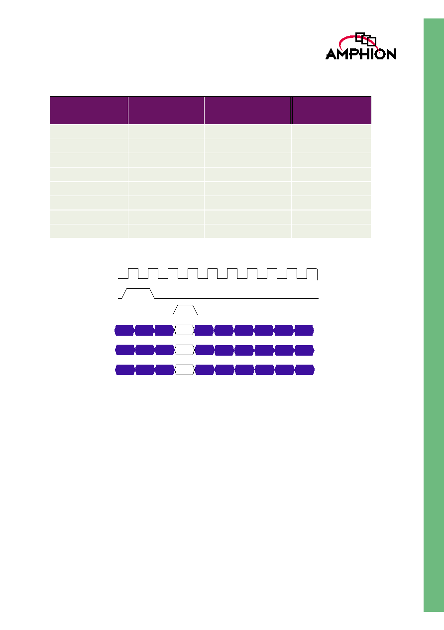
After the global asynchronous reset signal RST is applied, the
core is reset to the default mode: 2048-point FFT without the
additional shifting operation. Programming the core can be
performed at any time subsequently. The programming
signals are valid only when CLR is HIGH. This is illustrated
in Figure 3. It is noted that when CLR is applied the core is
reset as well.
Table 2: Programming Transform Type and Size
Port CFG
Port IFFT
Transform Type
Transform Size
00
0
Reserved
Reserved
00
1
Reserved
Reserved
01
0
FFT
2048-point
01
1
IFFT
2048-point
10
0
FFT
4096-point
10
1
IFFT
4096-point
11
0
FFT
8192-point
11
1
IFFT
8192-point
5
TM
Figure 3: Configuration Timing
INPUT AND OUTPUT DATA FORMAT
The input complex number data is represented by 16-bit real
and imaginary components, namely XRe and XIm, in the
two's complement format.
The input data is burst into the core in the normal order, i.e.,
X(0) enters the core first, followed immediately in the next
clock cycle by X(1), and then X(2), and so on so forth. It takes
2048, 4096 and 8192 clock cycles for a data block to enter the
core for transforms of 2048-point, 4096-point and 8192-point,
respectively.
The transform result is also complex numbers. They are
represented by 16-bit real components YRe and imaginary
components YIm in the two's complement format.
The output data is burst out from the core when the transform
has been performed to the stage that allows the result to be
output and the output port is enabled. The result from the
core is also in the normal order, i.e., Y(0) first, followed by
Y(1), Y(2) and so on so forth.
TRANSFORM COMPUTATION
The transform is scheduled to complete in three passes. In
each pass the controller fetches the intermediate data from the
internal dual port memory, sends it to the two processing
units, collects the computation results from the processing
units and writes them back to the memory for the next pass or
for the output.
In the first two passes, Processing Unit 1 performs 16-point
FFT on the intermediate data from the memory, using a
Cooley-Tukey radix-4 decimation-in-frequency (DIF)
algorithm. This involves two radix-4 butterflies and a 16-point
twiddle operation. The intermediate result value may grow by
a factor of up to 4*5.657, representing 4 to 5 bits word length
growth. Processing Unit 2 performs twiddle operations on the
Table 3: Programming Scaling Factor
Port SDC
Fixed Shifting
(bits)
Additional Shifting
(bits)
Scaling Factor
(
)
000
7
0
1/128
001
7
1
1/256
010
7
2
1/512
011
7
3
1/1024
100
7
4
1/2048
101
7
5
1/4096
110
7
6
1/8192
111
7
7
1/16384
2
7 SDC
+
(
)
≠
CLK
RST
CLR
CFG
IFFT
SDC