
TM
Virtual Components for the Converging World
Amphion continues to expand its family of application-specific cores
1
See http://www.amphion.com for a current list of products
CS2421
2048/8192-Point IFFT
Preliminary Datasheet
The CS2421 is an online programmable, 2048/8192-point Inverse Fast Fourier Transform (IFFT) core. This highly
integrated application specific silicon core is based on the radix-4 algorithm and performs 2048-point or 8192-
point IFFT algorithms in three computation passes. The CS2421 IFFT core is available in both ASIC and FPGA
versions that have been handcrafted by Amphion for maximum performance while minimizing power
consumption and silicon area.
Figure 1: CS2421 Architecture
Y
X
Processing Unit 1
Radix-2 /
Radix-4
Butterfly
Complex
Number
Multiplier
8/16
Point
Twiddle
Radix-4
Butterfly
Memory
Controller
I/O Interface and Transform Control
4096 x 32
Dual Port
Memory
4096 x 32
Dual Port
Memory
Processing Unit 2
Radix-2
Butterfly
Complex
Number
Multiplier
2048, 4096,
8192-point
Twiddle
Factor
Output
Buffer
CS2420
Guard
Control
CS2421
FEATURES
On-line programmable 2048/8192-point IFFT
core
16-bit complex input/output in two's
complement format (32-bit complex word)
16-bit twiddle factors generated inside the
core
18-bit fixed-point internal arithmetic operation
Programmable shift down control
Programmable guard interval control (1/32,
1/16, 1/8, 1/4)
Mixed radix-8/radix-16/radix-32 architecture
Transform performed in three computation
passes with zero-waiting
Simultaneous loading/downloading
supported
Burst input format
Burst or continuous output with guard
interval insertion
Both input and output in normal order
No external memory required
All synchronous design
Optimized for both ASIC and FPGA
technologies with the same functionality
APPLICATIONS
OFDM modulation scheme for DVB-T
(Ref: ETS 300 -744)
Image processing
Atmospheric imaging
Spectral representation
2
CS2421
2048/8192-Point IFFT
INVERSE FAST FOURIER TRANSFORM
IFFT (Inverse Fast Fourier Transform) is an algorithm
computing 2
P
-point inverse discrete Fourier transform, as
defined below:
IFFT:
, k = 0, 1, 2...N-1
[1]
Where N=2
P
and
.
The computational complexity of IFFT is proportional to
Nlog
R
N, where R is the radix base on which IFFT is
performed. The higher the radix, the less number of
multiplication is required, however the more simultaneous
multiple data access is required which causes the circuits to be
more complicated. The radix-4 algorithm offers a balance
between the computational and circuit complexity and is often
used in construction of higher radix FFT computation units
when designing high performance IFFT hardware.
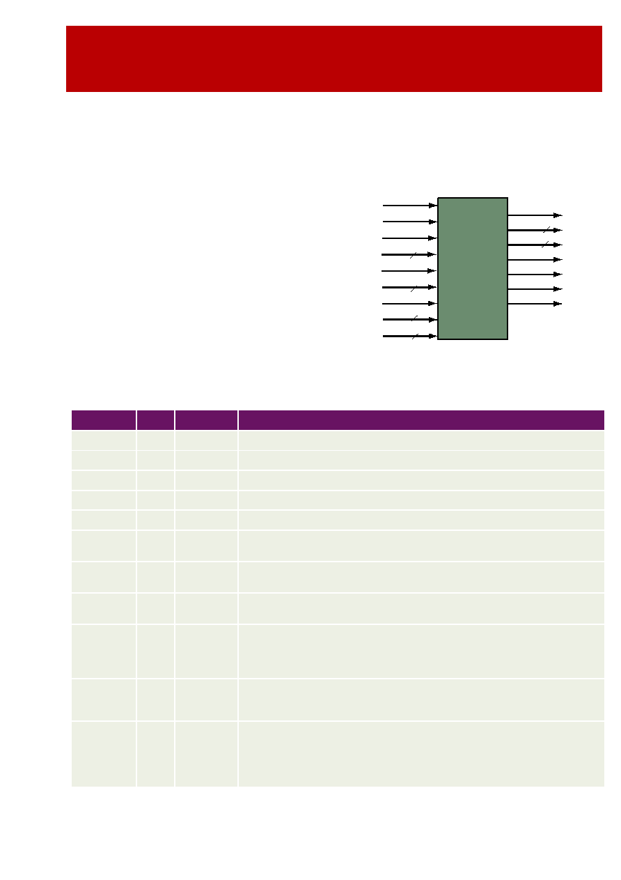
CS2421 SYMBOL
AND PIN DESCRIPTION
Table 1 describes input and output ports (shown graphically
in Figure 2) of the CS2421 2048/8192-point IFFT core. Unless
otherwise stated, all signals are active high and bit(0) is the
least significant bit.
Figure 2: CS2421 Symbol
Y k
( )
1
N
----
X n
( )
n
0
=
N 1
�
W
nk
N
=
e
j2
�
N
/
CS2421
2048/8192
Point
IFFT
Ylm
YRe
YS
Xlm
CLK
NotRST
16
XRe
16
CFG
GUARD
2
16
16
XBIP
Busy
YG
CLR
XBS
SDC
3
YOV
Table 1: CS2421 - 2048/8192 Point IFFT Interface Signal Definitions
Name
I/O
Width
Description
CLK
I
1
Clock signal, rising edge active
NotRST
I
1
Asynchronous global reset signal, active LOW
CLR
I
1
Clear (synchronous reset) and programming signal, active HIGH
GUARD
I
2
Programming signal specifying the guard interval, loaded when CLR is active
CFG
I
1
Programming signal specifying the transform size, loaded when CLR is active
SDC
I
3
Programming signal specifying the number of bits for the additional scaling down
operation, loaded when CLR is active
XRe
I
16
Real component of input data X, in two's complement format, burst into core on a
block by block scheme
XIm
I
16
Imaginary component of input data X, in two's complement format, burst into core on
a block by block scheme
XBS
I
1
Input data X block start signal, active HIGH, associated with the first input data of the
N-point block. The rest N-1 data of the N-point data block are loaded into the core in
the following N-1 clock cycles in the natural order. XBS must be asserted only on the
cycle after BUSY goes LOW to maintain correct guard interval insertion.
XBIP
O
1
Output signal indicating loading X is in Progress. XBIP goes to HIGH the next clock
cycle when XBS is active and returns to LOW when the last data of the N-point block
is loaded into the core. XBS is ignored when it is HIGH.
Busy
O
1
Output signal indicating the transform in progress (busy). It goes HIGH when the first
data of the N-point block is loaded into the core and returns to LOW when the core is
ready to accept the next input data block in the next clock cycle. XBS must be
asserted only on the cycle after BUSY goes LOW to maintain correct guard interval
insertion.

3
TM
FUNCTIONAL DESCRIPTION
CS2421 performs a mixed decimation in frequency (DIF),
radix-8, radix-16 and radix-32, inverse Fast Fourier
Transforms on 2048-point or 8192-point complex data block.
The transform is scheduled in three computation passes. Data
is loaded into the core in normal sequential (natural) order.
The transform result comes out from the core also in the
natural order. The core is on-line programmable on the guard
interval, transform size and scaling down control. The input
and output data and the twiddle factor wordlengths are
selected such that it can be used in a wide range of
applications. The core computes the transform using fixed-
point arithmetic with programmable shift down control on
each computation passes to handle the possible wordlength
growth and overflow in the transform. This achieves the
maximal accuracy possible while maintaining the desired
dynamic range for the output. The internal 8K 32-bit word
dual port memory is organized in two banks with 4K words
each. In 2048-point and 8192-point transform mode, only one
bank is enabled. This is to improve power consumption of the
core when it is operating for the smaller transform size. The
core is a synchronous design with all the flip-flops being
triggered at the rising edge of the clock signal CLK.
PROGRAMMING THE CORE
Programming CS2421 is performed when the core is
synchronously reset. This is done through asserting signal
CLR, applying to input ports CFG, GUARD and SDC. Port
CFG and GUARD specify the transform size and guard
interval. Table 2 lists the CFG and GUARD value for
programming the core to different transform size and guard
intervals.
The core performs 7-bit unconditional shifting down on the
internal data during the transform. However, theoretically the
2048-point and 8192-point IFFT may have up to 12 and 14 bit
word growth in total, respectively. The CS2421 core can
perform up to 7 bits controlled shift down operation to avoid
possible overflow and to allow the transform gain to be
controlled. This is programmed through port SDC. The total
number of shift down bits decides the transform scaling down
factor. Table 3 lists the SDC values for programming the
scaling factor.
After the global asynchronous reset signal RST is applied, the
core is reset to the default mode: 2048-point IFFT, 1/32 guard
interval. Programming the core can be performed at any time
subsequently. The programming signals are valid only when
CLR is HIGH. This is illustrated in Figure 3. It is noted that
when CLR is applied the core is reset as well.
YG
O
1
Output data Y guard indicator, active HIGH, asserted for the duration of the guard
interval and de-asserted during output symbol
YS
O
1
Output data Y symbol indicator, active HIGH, asserted for the duration of the output
symbol and de-asserted during the guard interval
YRe
O
16
Real component of output data Y, in two's complement format, continuously output
from core
YIm
O
16
Imaginary component of output data Y, in two's complement format, continuously out-
put from core
YOV
O
1
Output data Y overflow signal, active HIGH, asserted when overflow occurs when the
transform is performed. It is reset when a new transform starts and is associated with
the N-point block.
Table 1: CS2421 - 2048/8192 Point IFFT Interface Signal Definitions
Name
I/O
Width
Description
Table 2: Programming Transform Type and Size
Port CFG
Port GUARD
Guard
Interval
Transform
Size
0
00
1/32
2048-point
0
01
1/16
2048-point
0
10
1/8
2048-point
0
11
1/4
2048-point
1
00
1/32
8192-point
1
01
1/16
8192-point
1
10
1/8
8192-point
1
11
1/4
8192-point

4
CS2421
2048/8192-Point IFFT
Figure 3: Configuration Timing
INPUT AND OUTPUT DATA FORMAT
The input complex number data is represented by 16-bit real
and imaginary components, namely XRe and XIm, in the
two's complement format.
The input data is burst into the core in the normal order, i.e.,
X(0) enters the core first, followed immediately in the next
clock cycle by X(1), and then X(2), and so on. It takes 2048 and
8192 clock cycles for a data block to enter the core for
transforms of 2048-point and 8192-point, respectively. The
transform result is also complex numbers. They are
represented by 16-bit real component YRe and imaginary
components YIm in the two's complement format.
The output data is continuously output from the core when
the first input block transform has been performed to the
stage that allows the guard interval to be output. The result
from the core is also in the normal order with the guard being
output as Y(N-G), Y(N-(G-1)) to Y(N). Subsequently the
output symbol is Y(0) first, followed by Y(1), Y(2) etc.
TRANSFORM COMPUTATION
The transform is scheduled to complete in three passes. In
each pass the controller obtains the intermediate data from the
internal dual port memory, sends it to the two processing
units, collects the computation results from the processing
units and writes them back to the memory for the next pass or
for the output.
In the first two passes, Processing Unit 1 performs 16-point
IFFT on the intermediate data from the memory, using a
Cooley-Tukey radix-4 decimation-in-frequency (DIF)
algorithm. This involves two radix-4 butterflies and a 16-point
twiddle operation. The intermediate result value may grow by
a factor of up to 4*5.657, representing 4 to 5 bits word length
growth. Processing Unit 2 performs twiddle operations on the
16-point IFFT result from Processing Unit 1 for the
programmed transform size. In the third pass, Processing Unit
1 performs 16-point IFFT when the transform size is 8192-
point, using the same algorithm as that used in the first two
passes. It performs 8-point IFFT when the transform size is
2048-point, using a mixed radix-4 and radix-2 DIF algorithm.
For 8192-point transform, Processing Unit 2 performs 32-point
twiddle operation and a further radix-2 operation on the
result from Processing Unit 1. This, together with the
operations of Processing Unit 1, effectively forms a radix-32
operation. For 2048-point transform, Processing Unit 2
performs no operation in the third pass. The transform
operation performed in each pass is summarized in Table 4.
CS2421 performs scaling down operation by right shifting the
intermediate result in the three passes, according to the
scaling down control programmed. Table 5 lists the
relationship between the programming input signal SDC and
the number of scaling down bits performed in the three
passes. It is noted that for 2048-point and 8192-point
transform, there is no overflow in the computation when the
total number of shifting bits is equal to or more than 12, and
14 bits, respectively.
Table 3: Programming Scaling Factor
Port SDC
Fixed
Shifting
(bits)
Additional
Shifting
(bits)
Scaling Fac-
tor
(2
-(7+SDC)
)
000
7
0
1/128
001
7
1
1/256
010
7
2
1/512
011
7
3
1/1024
100
7
4
1/2048
101
7
5
1/4096
110
7
6
1/8192
111
7
7
1/16384
CLK
RST
CLR
CFG
SDC
GUARD
Table 4: Transform Operations in Each Pass
Transform
Size
Pass 1
Pass 2
Pass 3
2048-point
Radix-16
Radix-16
Radix-8
8192-point
Radix-16
Radix-16
Radix-32

5
TM
FIXED WORD LENGTH AND ACCURACY
CS2421 uses fixed-point arithmetic to perform the transform.
All the arithmetic operations involved have 16 bits or higher
accuracy. The twiddle factors (Sine and Cosine values), which
are generated by the core internally, have 16-bit accuracy. At
the end of each computation pass, the result is rounded to 16
bits. Figure 5 illustrates the word lengths at various
computation stages in the CS2421 core.
The rounding technique is employed to achieve the maximal
computation accuracy possible for the given word lengths.
When the intermediate value is derived from the twiddle
multiplication result, the output from the butterflies is scaled
down, or the intermediate result is right shifted, the core
performs the round-to-the-nearest operation to keep the loss
of accuracy minimal. Table 6 illustrates the simulation results
on the transform accuracy of CS2421 core. The results are
obtained by applying 100 blocks of 16-bit random input data
to the core while the scaling down control is set such that
there is just no overflow in the computation. For example, the
output magnitude is maximized while no overflow occurs.
The 16-bit output data from the core is compared with the
result of double precision IFFT model. The error is measured
in terms of the output LSB weight. It is noted that when
overflow occurs the transform accuracy will be decreased
severely.
Figure 4: Word Length in Arithmetic Operations
Table 5: Number of Right Shifting Bits in Each Pass
SDC
Pass 1
Pass 2
Pass 3
Total
000
3
3
1
7
001
4
3
1
8
010
4
3
2
9
011
5
3
2
10
100
5
4
2
11
101
5
4
3
12
110
5
4
4
13
111
5
4
5
14
Table 6: Simulation Result of Transform Accuracy
Transform Size
2048-point
8192-point
SCD setting
001
010
Scaling Factor
1/256
1/512
Number of complex data
samples compared
204800
819200
Maximal output Magni-
tude
15329
17935
Maximal Error
6
12
Average Absolute Output
2667
2670
Average Absolute Error
0.526
0.587
Mean Square Error
0.607
0.726
Average SNR
74.1dB
73.2dB
16 bits
18 bits
18 bits
16 bits
Radix-4
Butterfly
18 bits
16 or 18-point
Twiddle
Multiply
Radix-4
Butterfly
Radix-4
Butterfly
18 bits
16 bits
Radix-4
Butterfly
16 bits
Main
Twiddle
Multiply
Radix-2
Butterfly
(8192-pt)