
TM
Virtual Components for the Converging World
Amphion continues to expand its family of application-specific cores
1
See http://www.amphion.com for a current list of products
CS3114
High Speed G.709/G.975 Compliant
Reed-Solomon Encoder
The CS3114 Reed-Solomon Encoder is designed to provide high performance solutions for forward error
correction requirements and meets the ITU G.709 standard for Optical Transport Networks (OTN) providing
data rates higher than 10 Gbps. This core is developed for high performance digital video and audio, satellite
broadcast or data storage and retrieval applications and is fully compliant with the ITU G.709 standard. The
CS3114 RS encoder is available for both ASIC and programmable logic versions that have been handcrafted by
Amphion to deliver high performance while minimizing power consumption and silicon area.
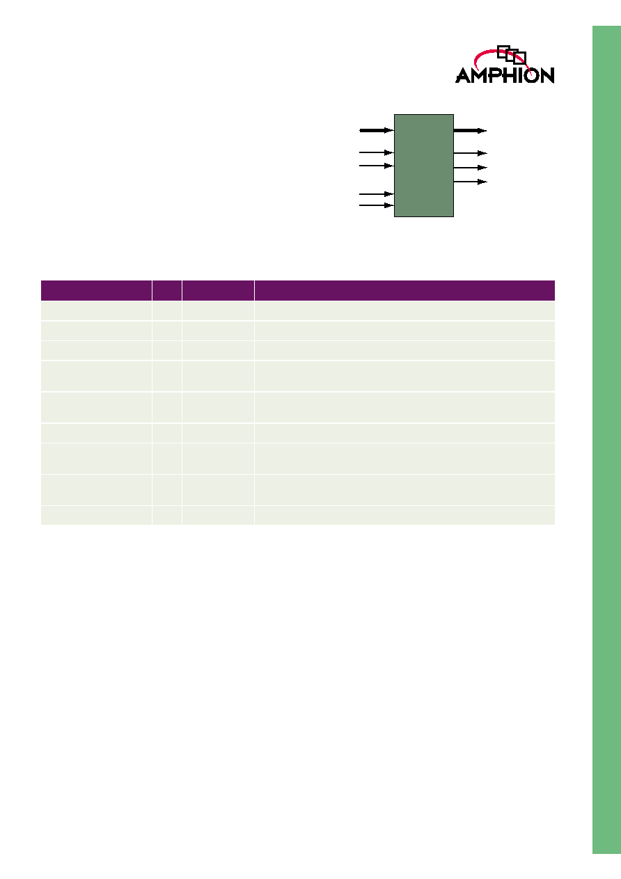
Figure 1: CS3114 Function
Input Data Steam
K
2
K
1
Output Data Stream
CS3114
RS Encoder
K
2
K
1
Parity
ENCODER FEATURES
Fully compliant with a ITU G.709/G.975
standard
High data rates > 2.4 Gbps in a single
instantiation
Total number of message symbols per block
k = 239
Number of check bytes per block (n-k) = 16
Capable of continuous or burst processing of
data blocks
Symbol wide input and output, clocked by a
single symbol rate clock
Simple core interface allows easy integration
into larger systems
Support of the following combinations of
generator polynomial, g(x), and field
polynomial, f(x):
where
is 02
HEX
KEY METRICS
Logic area:
2.8K Gates (STD Cells)
Performance:
>300 MSamples/sec
Input clock:
300 MHz (130nm, TSMC)
BENEFITS
Increases the performance of existing optical
networks
Lowers the number of repeaters in optical
networks
Increases the bandwidth for optical networks
APPLICATIONS
ITU G.709/G.975 compliant transport networks
SONET/SDH applications
High performance digital video and audio
High-rate LAN/MAN applications
Cable and satellite broadcast
g x
( )
x 1
+
(
) x
+
(
) x
2
+
(
)... x
2t 1
�
(
)
+
(
)
=
f x
( )
x
8
x
4
x
3
x
2
1
+
+
+
+
=

2
CS3114
High Speed G.709/G.975 Compliant Reed-Solomon Encoder
BLOCK CODES
FOR ERROR CORRECTION
The purpose of channel coding in digital communications
systems, is to introduce controlled redundancy into an
information sequence, which can be exploited by the receiver
to overcome the effects of data corruption caused by channel
distortions and noise. The encoding process generally
involves taking k information bits or symbols and mapping
them to a longer, unique sequence of n bits or symbols,
referred to as a code word. The amount of redundancy added
by the encoder is measured by the ratio n/k, and the reciprocal
of this value, namely k/n, is known as the coding rate.
Intuitively, lower coding rates imply greater degrees of added
redundancy, and hence greater robustness against errors. This
robustness is generally achieved at the expense of bandwidth
expansion, since a higher transmission rate must be
maintained for channel-coded data, due to the redundant data
added by the encoding process. The redundancy introduced
can be utilised to detect the occurrence of errors and request
retransmission (ARQ scheme) and/or correct errors (FEC
scheme).
Block codes are characterised by the independent coding of
successive blocks of information bits, or multi-bit symbols. For
each block, the values of the n coded bits or symbols are
computed solely from the values of the k information bits or
symbols. There are no dependencies between successive
blocks, and hence block codes for error detection and
correction are considered memoryless. If the information
sequence is coded as a sequence of bits, the code is binary,
while non-binary codes encode data as groups of symbols,
where a single symbol contains several bits. Reed-Solomon
codes are a particularly powerful type of non-binary linear
block code. A systematic (n, k) Reed-Solomon code takes k
information symbols and appends n-k redundant check (or
parity) symbols. This allows unassisted correction of up to [(n-
k) / 2] symbol errors per block of n symbols, and hence Reed-
Solomon coding is particularly effective against burst errors
introduced by the communications channel. In addition to the
number of added check symbols, a Reed-Solomon code is
characterised by a field polynomial and generator polynomial.
The coefficients of the field polynomial define a particular
finite field, which is an integral part of the mathematical
operations carried out during coding. The coefficients of the
generator polynomial are used to determine the check symbol
values for a particular information sequence.
CS3114 FUNCTIONAL DESCRIPTION
Figure 2 represents the main functional blocks and interfaces
for the CS3114 Reed Solomon encoder.
The CS3114 RS encoder consists of 3 primary blocks as shown
in Figure 2. A section of storage is reserved for the generator
polynomial coefficients for each of the 16 parity number
formats, the total number of symbols in the code word (code
word length), and the number of appended check symbols
(parity length).
The parity symbol calculation block is responsible for
producing the parity values from the input data sequence and
the generator polynomial coefficients. The count and control
circuitry performs internal control operations, and switches
the output data stream between the input information data
stream and the generated parity values.
Since the encoder is systematic, the first k output symbols are
identical to the input information sequence, and the n-k parity
symbols are then appended.
Figure 2: CS3114 Overview Diagram
Codeword
Generator
Coeffients
Parity (redundancy) calculation
Control Cirtuitry
DATA_OUT
DATA_VALID_OUT
FRAME_START_OUT
I_PO
CLK
RESn
DATA_IN
FRAME_START_IN
DATA_VALID_IN
3
TM
CS3114 SYMBOL
AND PIN DESCRIPTION
Table 1 describes input and output ports (shown graphically
in Figure 3) of the CS3114 G.709 compliant RS encoder. Unless
otherwise stated, all signals are active high and bit(0) is the
least significant bit.
Figure 3: CS3114 Symbol
CS3114
RS
ENCODER
DATA_IN
FRAME_START_IN
DATA_VALID_IN
CLK
RESn
DATA_OUT
I_PO
DATA_VALID_OUT
FRAME_START_OUT
Table 1: CS3114 RS Encoder Interface Signal Definitions
Signal
I/O
Width (Bits)
Description
Clk
I
1
Symbol rate clock, rising edge active
RESn
I
1
Asynchronous Master Reset, active low
DATA_IN
I
8
Input data symbol, 8 bits wide
FRAME_START_IN
I
1
When high, indicates the data on DATA_IN is the first symbol in a new
codeword sequence
DATA_VALID_IN
I
1
When high, signifies that the signals at the DATA_IN and
FRAME_START_IN ports contain valid information
DATA_OUT
O
8
Output data symbol, 8 bits wide.
FRAME_START_OUT
O
1
When high, indicates the data on DATA_OUT is the first symbol in a
new coded block
DATA_VALID_OUT
O
1
When high, signifies that the signals at the DATA_OUT and
FRAME_START_OUT ports contain valid information
I_PO
O
1
Indicates the present symbol is message (1) or parity (0) data.

4
CS3114
High Speed G.709/G.975 Compliant Reed-Solomon Encoder
OPERATIONAL DESCRIPTION
The following sections describe the operation of the Reed
Solomon encoder.
RESET AND CLOCKING STRATEGY
All synchronous elements in the RS encoder are clocked using
the rising edge of the CLK signal. Additionally, all I/O signals
are registered on the rising edge of CLK, with the exception of
RESn. When the reset signal RESn is asserted, all registers will
be set to their default reset value.
INPUT DATA INTERFACE
DATA_VALID_IN
The DATA_VALID_IN signal should be asserted whenever
valid data is present on DATA_IN and appropriate flags are
driven at the FRAME_START_IN input. DATA_VALID--_IN
acts as a clock enable for the input codeword and if de-
asserted, the encoder will not sample the signals at
FRAME_START_IN and DATA_IN. Therefore, there is no
requirement for the codeword sequence to be input in a
continuous stream. If DATA_VALID_IN is de-asserted after a
complete message sequence has been input, the encoder
continues to process the received message and output the
corrected message, despite the fact that the input data flow
has stalled. Symbols placed on DATA_IN will be ignored
when DATA_VALID_IN is de-asserted.
FRAME_START_IN
FRAME_START_IN should be asserted for one clock cycle at
the same time as the first information symbol in a new
sequence is applied to DATA_IN simultaneously with
DATA_VALID_IN asserted.
If FRAME_START_IN is asserted at the beginning of a
codeword and subsequently reasserted before the message
has completely entered the encoder, the partially entered
message will be discarded and processing begun again at the
latest assertion of FRAME_START_IN.
OUTPUT DATA INTERFACE
DATA_OUT
The encoded Reed Solomon symbols are output on the
DATA_OUT port latency clock cycles after the equivalent Reed
Solomon symbols were clocked in on the DATA_IN port. All
valid data output from this port is marked as such by the
simultaneous assertion of the DATA_VALID_OUT signal. The
first symbol of an output message is marked as such by the
simultaneous assertion of the FRAME_START_OUT signal.
FRAME_START_OUT
FRAME_START_OUT is asserted high for one clock cycle
duration at the same time as the first code word symbol of the
encoder output appears on DATA_OUT.
DATA_VALID_OUT
When valid information symbols are present on DATA_OUT,
the output DATA_VALID_OUT signal is asserted high. Once a
complete codeword has been output from the encoder
DATA_VALID_OUT is de-asserted until the next encoded
message is output.
I_PO
When the symbols being output from the encoder are message
symbols, flag I_PO will be asserted high and when the
symbols being output are parity symbols, flag I_PO will be
asserted low. Therefore I_PO will be high for the first 239
symbols of the output codeword and low for the remaining 16
output codeword symbols.

5
TM
TIMING DIAGRAMS
Figure 4 shows the functional timing of the CS3114 RS
encoder:
Figure 4: CS3114 RS Encoder Functional Timing Diagram
CLK
DATA_IN
FRAME_START_IN
DATA_VALID_IN
k symbols
DATA_OUT
FRAME_START_OUT
DATA_VALID_OUT
I_PO
n symbols
k symbols