
TM
Virtual Components for the Converging World
Amphion continues to expand its family of application-specific cores
1
See http://www.amphion.com for a current list of products
CS3210/12
Reed-Solomon Decoders
The CS3210 and CS3212 Reed-Solomon decoders are designed to provide high performance solutions for a broad
range of applications requiring forward error correction. These application specific virtual components (ASVCs)
are developed for high data rate digital video and audio, satellite broadcast or data storage and retrieval
applications, and are fully compliant with the European DVB (CS3210) and IntelSat (CS3212). The ASVCs are
configurable Reed-Solomon decoders featuring user-selectable codeword length (50-255 symbols) and number of
parity symbols (0-20 symbols), providing up to 880Mbits per second data throughput. The CS3210 and CS3212
are available in both ASIC and programmable logic versions that have been handcrafted by Amphion for optimal
performance while minimizing power consumption and silicon area.
Figure 1: CS3210/12
Input Data Steam
symbols
N=50-255
K
2
K
1
Output Data Stream
symbols
N=50-255
CS3210
or
CS3212
K
2
K
1
Parity
DECODER FEATURES
Configurable Codeword Length (N) and
Number of Parity Symbols (T)
-
N = 50 � 255 symbols
-
T = 0 � 20 symbols
-
Single implementation supports any valid
block length and parity length
High Performance Solution for High Data Rate
Reed-Solomon Decoding
-
Can process burst and continuous data
-
Low latency
Supports a Range of Standards Including
Intelsat, European DVB Telecommunication
Standards ETS 300-421 and ETS 300-429
Byte-Wide Input and Output, Clocked by a
Single Symbol Rate Clock
Ease of Integration
-
Tapeout-ReadyTM firm-IP targeted netlist
-
Simple core interface for easy integration into
larger systems
KEY METRICS
AND SPECIFICATIONS
Size:
104k Gates
Maximum Frequency:
110 MHz
1
8 Bits per Symbol Yields 880 Mbits/second
1
Throughput
CS3210 (DVB Compliant)
-
Generator Polynomial:
g(x)=(x+1)(x+a)(x+a
2
). . .(x+a
(2t-1)
) [
2
]
-
Field Polynomial: f(x)=x
8
+x
4
+x
3
+x
2
+1
CS3212 (Intelsat Compliant)
-
Generator Polynomial:
g(x)=(x+a
120
)(x+a
121
). . .(x+a
120+(2t-1)
)
-
Field Polynomial: f(x)=x
8
+x
7
+x
2
+x+1
APPLICATIONS
Digital video and Audio Broadcast
Digital Satellite Broadcast
Data Storage and Retrieval Systems
(e.g. Hard Disk Drives, CD-ROM, DVD, etc.)
1.
Performance is dependent on the silicon process and libraries selected. 110MHz/880Mbps operation is representative of 0.18-micron silicon using standard cell libraries.
2.
"t" represents the number of correctable symbol errors (excluding erasures) and equals one-half the number of parity symbols "T".

2
CS3210/12
Reed-Solomon Decoders
BLOCK CODES FOR ERROR CORRECTION
In digital communications systems, channel coding is used to
introduce controlled redundancy into a data sequence on the
transmission (encode) side of a communications channel. The
receiver (decoder) uses this redundant information to
overcome the effects of data corrupting channel distortions
and noise. Block codes are a type of channel coding scheme
characterized by the independent coding of successive
discrete blocks or groups of information bits with no
dependencies between successive blocks of data. Binary codes
operate on sequences of bits, whereas non-binary codes
decode data as multi-bit symbols � 8 bits per symbol for most
applications. Reed-Solomon codes are a particularly powerful
type of non-binary, linear block code.
The CS3210 and CS3212 are designed to provide high
performance forward error correction (FEC) compliant with
digital video broadcast (DVB) standards and other
applications using the Reed-Solomon technique. The core is
capable of processing both burst and continuous data streams
and input and out-put will be symbol wide, clocked by a
single symbol rate clock. The implementation is low latency
and the simple core interface allows easy integration into
larger systems.
The decoder accepts an input block consisting of data with
appended parity symbols and outputs the corrected (if
necessary) code block. As shown in Figure 1, the length of the
input data stream "N" ranges between 50 and 255 symbols and
is a function of the original code block "K" and parity symbols
"T". K ranges between 50 to 255 symbols. Between T/2 and T
errors can be detected and corrected by the decoder,
depending on the specific mix of erasure and random errors.
CS3210/CS3212 OPERATION
Within the Reed-Solomon decoder structure, there are 7
primary blocks as shown in Figure 2. Operation of key
individual blocks is described below. User programmable
registers are provided which allow the codeword length and
number of parity symbols to be defined. These are
programmed via a standard microprocessor type interface.
DECODER
The decoding calculation is subdivided into 5 components
performing the decoding calculation along with a FIFO used
to store codewords input to the core. The operation of the
FIFO is to present uncorrected codewords for the application
of correction symbols calculated in the main body of the
decoder. A description of the individual functional blocks
follows.
SYNDROME CALCULATION
The Syndrome Calculation Block contains control circuitry to
ensure that complete and valid codewords are applied to the
decoder. For a code with NCB ("number of check bytes")
parity symbols, a set of NCB syndromes are produced. The
values of these syndromes are subsequently forwarded to
error location and evaluation circuitry to resolve the positions
and magnitudes of codeword errors.
ERASURE CALCULATION
Operating in parallel with the Syndrome calculator is the
Erasure Calculator. Forward error correction systems often
include concatenated schemes to provide higher coding gains
than are achievable with a Reed-Solomon correction system in
isolation. These concatenated systems provide the Reed-
Solomon decoder with information regarding symbols that
are suspected of being received erroneously. Known as
erasures, such symbols are flagged as potentially incorrect; the
ability of the decoder to repair erased symbols extends its
correction ability. Normally the number of corrected symbols
is limited to half the number of parity symbols, while using
the Erasure Calculator means that up to twice as many erasure
errors may be corrected. For combinations of erasure errors (s)
and random errors (v), the total number of errors correctable
by a (n,k) code is given by
The decoder stores and forwards locations of erased symbols
to the key equation calculation module concurrently with the
syndromes from the Syndrome Calculation Block.
Figure 2: CS3210/CS3212 Block Diagram
s 2v
+
N K
�
Erased
Input
Register
Erasure
Calculation
Syndrome
Calculation
Key Equation
Calculation
Polynomial
Evaluation
Forney
Calculation
Fstart_Out
Code Word FIFO
Fstart_in
Data_Valid_In
Data_In
Data_Out
Data_Valid_Out
up_Dout
up_Din
Add
Wr
Rd
Reset Clk
3
TM
KEY EQUATION BLOCK
Solving the key equation is a complex iterative process, and
this module constitutes the main arithmetic engine of the
CS3210/CS3212. Inputs from the Syndrome and Erasure
Blocks are used to check if the received codeword contains
errors. This is performed by the calculation of polynomials
that describe the positions and values of any errors discovered
in the codeword. The key equation calculation occurs after the
Syndrome Calculation Block signals that a complete Reed-
Solomon codeword has been received and the syndrome and
erasure values are available. The greater the value of (N-K),
the more iterations are necessary to complete the calculations.
It should be noted that this is independent of the number of
actual errors in the received codeword.
It is the processing delay incurred in the solution of the Key
Equation that limits the minimum value of N for a required
number of parity symbols when continuous messages are
received by the CS3210. Smaller values of N may be used, but
messages should then be burst to the core, with appropriate
gaps between the end of one and the start of the next, in order
that the Key Equation calculation may be solved between
subsequent sets of syndromes.
POLYNOMIAL EVALUATION
After the key equation is solved, the Polynomial Evaluation
block finds the roots of the above-mentioned polynomials.
This requires successive Galois Field multiplications and
addition of the resulting components, producing a set of data
that is related to the correction vectors which are then applied
to the received codeword. The presence of a
-1
values in the
location datastream implies a symbol in need of correction.
The evaluation values are used to calculate the value required
to correct the located error.
FORNEY COMPUTATION
The Forney algorithm is used to perform the final evaluation
calculation and the application of the correction vectors to the
received codewords. Often systems using Reed-Solomon
decoding need to know when an uncorrectable block has been
received. Normally it is not possible for the decoder to
determine if it can correct all errors until the complete block
has been processed. In order therefore to flag this condition
(that a block cannot be corrected) simultaneously with the
output of a codeword, it is necessary to perform the
correctability check and buffer the codeword for a codeword
length before applying the correction vectors. Uncorrectable
blocks are flagged as soon as their first symbol is output and
erroneous correction vectors are not applied to uncorrectable
blocks.
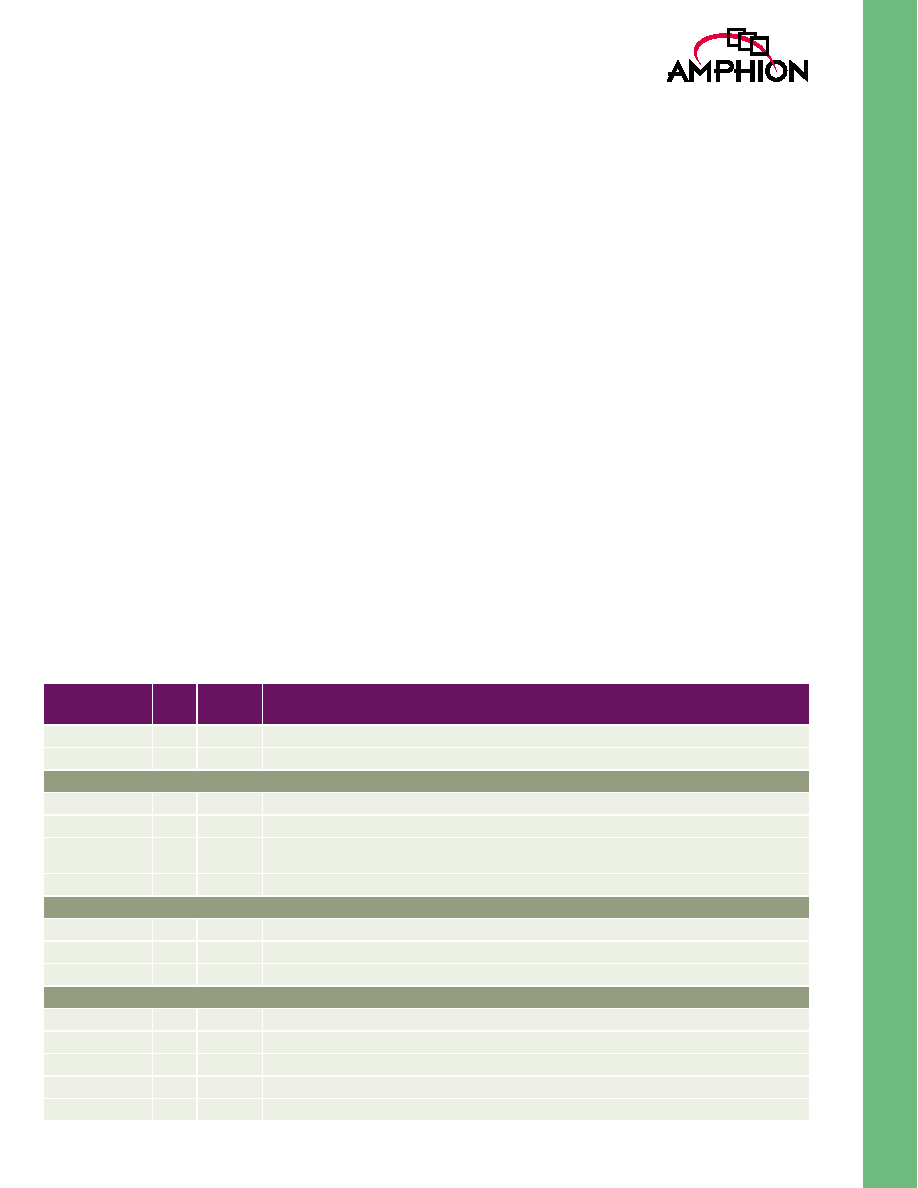
PIN/PORT DESCRIPTION
Table 1 gives the descriptions of the input and output ports of
the CS3210 and CS3212 Reed-Solomon decoders. Unless
otherwise stated, all signals are active high and bit (0) is the
least significant bit.
Table 1: Input and Output Descriptions
Signal
I/O
Width
(Bits)
Description
CLK
I
1
Symbol rate clock, rising edge active
Reset
I
1
Asynchronous Master Reset, active high
Data Stream Input Port
Data_In[7:0]
I
8
Input data symbol, 8 bits wide
FStart_In
I
1
When high, indicates the data on Data_In is the first symbol in a new information sequence
Data_Valid_In
I
1
When high signifies that the signals at the Data_In, Erased and F_Start_In ports contain valid informa-
tion
Erased
I
1
When high, signifies that the data on Data_In has been flagged as an erasure
Data Stream Output Port
Data_Out[7:0]
O
8
Output data symbol, 8 bits wide
FStart_Out
O
1
When high, indicates the data on Data_Out is the first symbol in a new coded block
Data_Valid_Out
O
1
When high, signifies that the signals at the Data_Out and FStart_Out ports contain valid information
Control and Configuration
UP-Din[7:0]
I
8
Data Bus input from microprocessor
Add[1:0]
1
2
Address Bus from microprocessor
RD[1:0]
I
1
Read Enable for Data Bus
WR
I
1
Write Enable for Data Bus
UP_Dout[7:0]
O
8
Data Bus output to microprocessor

4
CS3210/12
Reed-Solomon Decoders
PROCESSOR INTERFACE
Before the decoder can commence operation, the codeword
length and the parity length must be loaded into their
appropriate registers via the microprocessor interface. The
addresses of the respective registers are given in Table 2.
When changing codeword formats the user must ensure that
the there is no partially processed data within the CS3210,
which occurs after the latency has expired. Changing the
codeword format while the core is still processing will cause
unpredictable behavior until such time as the codeword
format is changed in the correct manner.
Values are loaded into their respective registers by applying
the correct address signal to Add, the parameter values to
UP_Din and then asserting the write enable signal. The inputs
Add and UP_Din are sampled on the write signal, WR, rising
edge. Polling the addresses 00 and 01 (CWL_REG and
NCB_REG) will output the current codeword length and
number of check bytes used in the decoder on the rising edge
of RD. Addressing 10 and strobing RD will output the number
of errors corrected in the codeword presently output at
SYMBOL_OUT. In cases where the current codeword is
uncorrectable a value of "11111111" will be output on
UP_DOUT on reading address 10.
CODEWORD FORMATS
The number of symbols within a codeword (N) may be varied
between 50 and 255. The number of these symbols that are
parity (N-K) may be varied between 0 and 20.
It should be noted that not all combinations of codewords are
valid. Due to the processing delay of the decoder it is not
possible to decode continuous messages for small values of N
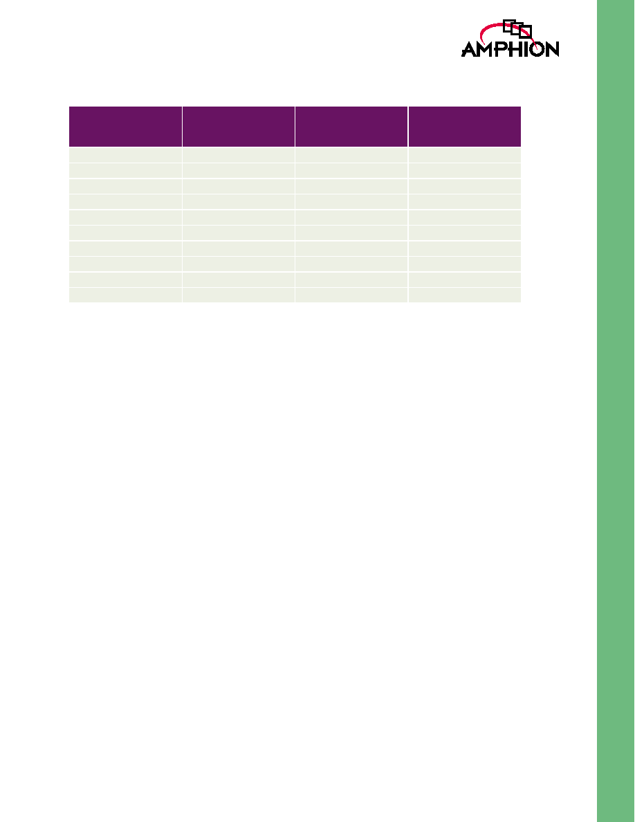
with large values of (N-K). Table 3 outlines the minimum
codeword length allowable for a given number of check
symbols for the processing of continuous messages.
Shorter codeword formats may be used for larger values of N-
K; however, it will be necessary to insert gaps between the
codewords entering the decoder to ensure that the core
operates correctly. This gap must be long enough to allow for
the equivalent number of clock cycles required to extend the
codeword length to the minimum allowed for the required
value of N-K. For example: an application requires a code-
word format of N=100 and N-K=16. From Table 3 it can be
observed that the minimum value of N required for this
number of parity symbols is 155. For this application,
messages in the required format can be processed as long as a
gap of 55 clock cycles is inserted between the last symbol in a
given codeword and the first symbol of the next codeword,
satisfying the minimum processing time of 155 cycles.
Also note that the absolute minimum codeword length is 50
under any conditions.
Table 2: Register Address Contents for Microprocessor Interface
ADDRESS
REGISTER
CONTENTS
CONTENT WIDTH
00
CWL_REG
Codeword Length
8 bits
01
NCB_REG
Number of Check Bytes
8 bits
10
STAT_REG
Statistics Output
8 bits
11
Not used
N/A
5
TM
SETTING THE CODEWORD FORMAT
With Data_Valid_In low (hence values on FStart_In, Data_In
and Erased are ignored), the number of check bytes register
(NCB_REG) should be addressed by placing the 2 bit binary
value "01" on the Add input port. Simultaneously, the required
number of check bytes used in the received code-words
should be placed in binary format on the UP_Din port. With
the values on Add and UP_Din held constant, the WR input
should be strobed high and low for the duration of one clock
cycle.
Once the number of check bytes has been set, the codeword
length may be input. Again with Data_Valid_In remaining low,
the codeword length register can be addressed (CWL_REG)
by placing the 2 bit binary value "00" on the microprocessor
interface port Add. Simultaneously, the required number of
symbols in each codeword of the received messages
(information symbols and parity symbols) should be set on
the UP_Din port. With the values on Add and UP_Din held
constant, the WR input should be strobed high and low for 1
system clock duration. Loading of Reed-Solomon messages
may commence with the following rising clock edge.
RESET AND CLOCKING STRATEGY
All synchronous elements in the decoders are clocked using
the rising edge of the CLK signal. The exceptions to this are the
registers holding the generator polynomial coefficients,
codeword length and parity length. These are written and
read using strobe signals present in the processor interface.
Additionally, all I/O signals are registered on the rising edge
of CLK, with the exception of Reset. When the reset signal
Reset is asserted, all registers will be set to zero value. The
codeword length register will be loaded with the value FF
HEX
(255
10
) and the parity length register will be loaded with the
value 10
HEX
(16
10
). The code generator polynomial registers
are loaded with the corresponding coefficients for the given
parity length. The default code rate is therefore (255, 239).
Table 3: Minimum Allowable Codeword Lengths
NUMBER OF
CHECK BYTES
MINIMUM
CODEWORD
LENGTH
NUMBER OF
CHECK BYTES
MINIMUM
CODEWORD
LENGTH
20
207
19
194
18
180
17
167
16
155
15
142
14
131
13
120
12
110
11
99
10
90
9
81
8
72
7
65
6
57
5
50
4
50
3
50
2
50
1
50