TM
Virtual Components for the Converging World
Amphion continues to expand its family of application-specific cores
1
See http://www.amphion.com for a current list of products
CS3214
High Speed G.709/G,975 Compliant Reed-
Solomon Decoder - Preliminary Datasheet
The CS3214 Reed-Solomon Decoder is designed to provide high performance solutions for forward error
correction requirements and meets the ITU G.709 standard for Optical Transport Networks (OTN) providing
data rates higher than 10 Gbps. This core is developed for high performance digital video and audio, satellite
broadcast or data storage and retrieval applications and is fully compliant with the ITU G.709 standard. The
CS3214 RS decoder is available for both ASIC and programmable logic versions that have been handcrafted by
Amphion to deliver high performance while minimizing power consumption and silicon area.
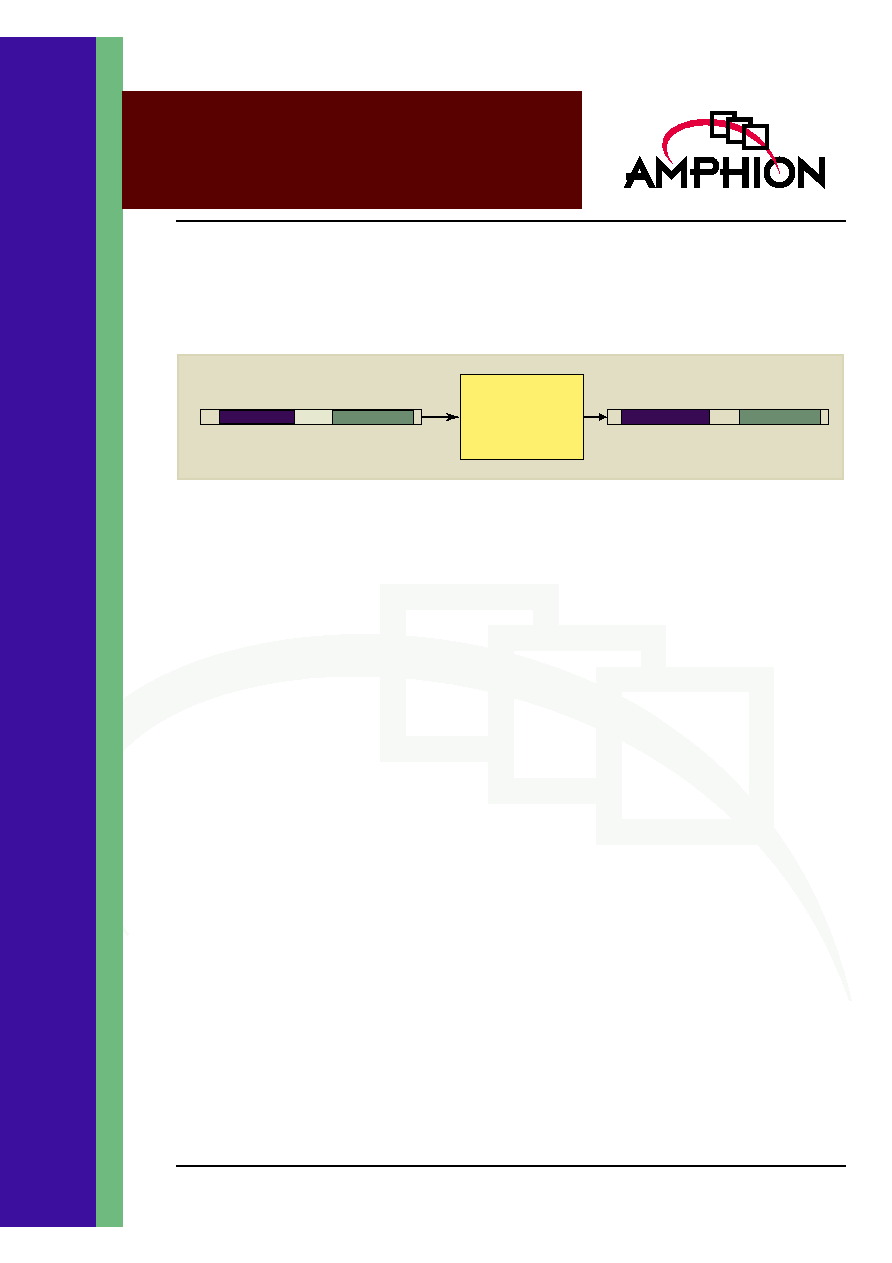
Figure 1: CS3214 Function
Input Data Steam
K
2
K
1
Output Data Stream
CS3214
RS Decoder
K
2
K
1
Parity
ENCODER FEATURES
Fully compliant with the ITU G.709/G.975
standards
High data rates > 2.4 Gbps in a single
instantiation
Total number of message symbols per block
k = 255
Number of check bytes per block (n-k) = 16
Capable of continuous or burst processing of
data blocks
Symbol wide input and output, clocked by a
single symbol rate clock
Simple core interface allows easy integration
into larger systems
Support of the following combinations of
generator polynomial, g(x), and field
polynomial, f(x):
where
is 02
HEX
KEY METRICS
Logic area:
20.6 K Gates (STD Cells)
Memory:
26K gates
Input clock:
300 MHz
BENEFITS
Increases the performance of existing optical
networks
Lowers the number of repeaters in optical
networks
Increases the bandwidth for optical networks
APPLICATIONS
ITU G.709/G.975 compliant transport networks
SONET/SDH applications
High performance digital video and audio
High-rate LAN/MAN applications
Cable and satellite broadcast
g x
( )
x 1
+
(
) x
+
(
) x
2
+
(
)... x
2t 1
+
(
)
+
(
)
=
f x
( )
x
8
x
4
x
3
x
2
1
+
+
+
+
=

2
CS3214
High Speed G.709/G.975 Compliant Reed-Solomon Decoder
BLOCK CODES
FOR ERROR CORRECTION
The purpose of channel coding in digital communications
systems, is to introduce controlled redundancy into an
information sequence, which can be exploited by the receiver
to overcome the effects of data corruption caused by channel
distortions and noise. The encoding process generally
involves taking k information bits or symbols and mapping
them to a longer, unique sequence of n bits or symbols,
referred to as a code word. The amount of redundancy added
by the encoder is measured by the ratio n/k, and the reciprocal
of this value, namely k/n, is known as the coding rate.
Intuitively, lower coding rates imply greater degrees of added
redundancy, and hence greater robustness against errors. This
robustness is generally achieved at the expense of bandwidth
expansion, since a higher transmission rate must be
maintained for channel-coded data, due to the redundant data
added by the encoding process. The redundancy introduced
can be utilised to detect the occurrence of errors and request
retransmission (ARQ scheme) and/or correct errors (FEC
scheme).
Block codes are characterised by the independent coding of
successive blocks of information bits, or multi-bit symbols. For
each block, the values of the n coded bits or symbols are
computed solely from the values of the k information bits or
symbols. There are no dependencies between successive
blocks, and hence block codes for error detection and
correction are considered memoryless. If the information
sequence is coded as a sequence of bits, the code is binary,
while non-binary codes encode data as groups of symbols,
where a single symbol contains several bits. Reed-Solomon
codes are a particularly powerful type of non-binary linear
block code. A systematic (n, k) Reed-Solomon code takes k
information symbols and appends n-k redundant check (or
parity) symbols. This allows unassisted correction of up to [(n-
k) / 2] symbol errors per block of n symbols, and hence Reed-
Solomon coding is particularly effective against burst errors
introduced by the communications channel. In addition to the
number of added check symbols, a Reed-Solomon code is
characterised by a field polynomial and generator polynomial.
The coefficients of the field polynomial define a particular
finite field, which is an integral part of the mathematical
operations carried out during coding. The coefficients of the
generator polynomial are used to determine the check symbol
values for a particular information sequence.
CS3214 FUNCTIONAL DESCRIPTION
Figure 2 represents the main functional blocks and interfaces
for the CS3214 Reed Solomon decoder.
The CS3214 RS decoder consists of 6 primary blocks as shown
in Figure 2. The following sections briefly describe the
functionality of each block.
Figure 2: CS3214 Overview Diagram
Input
Register
Code Word FIFO
DATA_IN
DATA_VALID_IN
Syndrome
Calculation
Key
Equation
Calculation
Polynomial
Evaluation
Forney
Calculation
FRAME_VALID_IN
RESn
CLK
DATA_OUT
I_PO
FRAME_START_OUT
DATA_VALID_OUT
UNCORR
CORR
CORR_VEC

3
TM
RS_DECODER
This block contains the circuitry for the total decoding
calculation and a FIFO to store the codewords input to the
core. The operation of the FIFO is to present uncorrected
codewords for the application of correction symbols
calculated in the main body of the decoder. The decoding
calculation is subdivided into 5 components.
All input signals are registered on the rising edge of the signal
CLK for being input to the core. This eases integration of the
RS decoder with other components and simplifies timing
characterization when performing system level integration.
All output signals are driven from registers on the rising edge
of the signal CLK.
Syndrome Calculation
The Syndrome Calculation block contains control circuitry to
ensure that complete and valid codewords are applied to the
decoder. For a code with (n - k) parity symbols a set of (n - k)
syndromes are produced. The values of these syndromes are
subsequently forwarded to error location and evaluation
circuitry to resolve the positions and magnitude of codeword
errors.
Key Equation Block
Solving the key equation is a complex iterative process and
this block constitutes the main arithmetic engine of the RS
decoder. The syndromes are used to check if the received
codeword contains errors. This is performed by the
calculation of location and evaluation polynomials, which
combine to mathematically describe the positions and values
respectively of any errors discovered in the codeword. The
key equation unit is dormant until the Syndrome calculation
unit signals that a complete Reed Solomon codeword has been
received and the syndrome values are ready to be loaded.
Locator and evaluator polynomials are found by iteration. The
greater (n - k) is, the more iterations are necessary to complete
the calculations. The number of iterations required is
independent of the number of errors in the received
codeword.
Polynomial Evaluation
The following stage of processing (Polynomial Evaluation)
concerns the finding of the roots of the polynomials
mentioned above. This requires the implementation of
successive Galois field multipliers and the addition of the
resulting components to produce a set of datastreams
pertaining to the correction vectors to be applied to the
received codeword. The presence of
-1
(zero) values in the
location datastream implies a symbol in need of correction.
The evaluation datastream may be used to calculate the value
required to correct the located error.
Forney Computation
The Forney algorithm unit is used to perform the final
evaluation calculation and the application of the correction
vectors to the received codewords. Often using Reed Solomon
decoding, the system requires knowledge that an
uncorrectable block has been received. It is not possible to
determine whether a codeword is correctable until the
decoder has completely processed the entire codeword.
Codeword Buffer
The codeword buffer comprises a block of dual port RAM and
associated control circuitry. The buffer operates as to read in
complete codeword messages from the DATA_IN input. On
completion of the decoding operation symbols are read from
the buffer in the FORNEY block in order to be added to the
erroneously received symbols in the codeword under
correction.
Control in the codeword buffer manages the reading and
writing of Reed Solomon symbols. The control logic also
ensures that the decoder can operate correctly even when
operated in an improper manner. Correction of a codeword is
not initiated until that codeword has been completely
received. Hence if a new codeword is begun before the
previous codeword has been completely entered, the
codeword buffer will overwrite the partially received message
giving preference to the new message. Similarly if more than
"n" valid symbols are entered into the decoder between
successive FRAME_START_IN flags the excess symbols are
ignored.
The control logic's effective role in managing the acceptance
only of full codeword messages gives the core the ability to
demonstrate a wide range of flexibility in dealing with
continuous and burst messages, as well as aborted messages.

4
CS3214
High Speed G.709/G.975 Compliant Reed-Solomon Decoder
CS3214 SYMBOL
AND PIN DESCRIPTION
Table 1 describes input and output ports (shown graphically
in Figure 3) of the CS3214 G.709 compliant RS core. Unless
otherwise stated, all signals are active high and bit(0) is the
least significant bit.
Figure 3: CS3214 Symbol
CS3214
RS
DECODER
DATA_IN
FRAME_START_IN
DATA_VALID_IN
CLK
RESn
DATA_OUT
I_PO
DATA_VALID_OUT
FRAME_START_OUT
CORR
UNCORR
CORR_VEC
Table 1: CS3214 RS Decoder Interface Signal Definitions
Signal
I/O
Width (Bits)
Description
CLK
I
1
Symbol rate clock, rising edge active
RESn
I
1
Asynchronous Master Reset, active low
DATA_IN
I
8
Input data symbol, 8 bits wide
FRAME_START_IN
I
1
When high, indicates the data on DATA_IN is the first symbol in a new
codeword sequence
DATA_VALID_IN
I
1
When high, signifies that the signals at the DATA_IN and
FRAME_START_IN ports contain valid information
DATA_OUT
O
8
Output data symbol, 8 bits wide.
FRAME_START_OUT
O
1
When high, indicates the data on DATA_OUT is the first symbol in a
new coded block
DATA_VALID_OUT
O
1
When high, signifies that the signals at the DATA_OUT and
FRAME_START_OUT ports contain valid information
I_PO
O
1
Indicates the present symbol is message (1) or parity (0) data.
CORR
O
1
Flag indicates that the decoder has corrected the data present at
DATA_OUT.
CORR_VEC
O
8
Indicates the value of the error found at the present symbol.
UNCORR
O
1
Flag indicates that the present codeword has been determined uncor-
rectable by the decoder's correction algorithms

5
TM
OPERATIONAL DESCRIPTION
The following sections describe the operation of the Reed Solomon decoder.
RESET AND CLOCKING STRATEGY
All synchronous elements in the RS decoder are clocked using
the rising edge of the CLK signal. Additionally, all I/O signals
are registered on the rising edge of CLK, with the exception of
RESn. When the reset signal RESn is asserted, all registers will
be set to their default reset value.
INPUT DATA INTERFACE
DATA_VALID_IN
The DATA_VALID_IN signal should be asserted when valid
data is present on DATA_IN and appropriate flags are driven
at the FRAME_START_IN input. DATA_VALID_IN acts as a
clock enable for the input codeword and if de-asserted, the
decoder will not sample the signals at FRAME_START_IN and
DATA_IN. Therefore, there is no requirement for the
codeword sequence to be input in a continuous stream. If
DATA_VALID_IN is de-asserted after a complete codeword
sequence has been input, the decoder continues to process the
received message and output the corrected message, despite
the fact that the input data flow has stalled. Symbols placed
on DATA_IN will be ignored when DATA_VALID_IN is de-
asserted.
FRAME_START_IN
FRAME_START_IN should be asserted for one clock cycle at
the same time as the first information symbol in a new
sequence is applied to DATA_IN simultaneously with
DATA_VALID_IN asserted.
Once a complete codeword has been received the entire
codeword is processed through the decoder and output when
the core latency has expired. If FRAME_START_IN is asserted
at the beginning of a codeword and subsequently reasserted
before the codeword has completely entered the decoder, the
partially entered codeword will be discarded and processing
begun again at the latest assertion of FRAME_START_IN.
OUTPUT DATA INTERFACE
DATA_OUT
The decoded Reed Solomon symbols are output on the
DATA_OUT port latency clock cycles after the last Reed
Solomon symbols was clocked in on the DATA_IN port. All
valid data output from this port is marked as such by the
simultaneous assertion of the DATA_VALID_OUT signal. The
first symbol of an output message is marked as such by the
simultaneous assertion of the FRAME_START_OUT signal.
FRAME_START_OUT
FRAME_START_OUT is asserted for one clock cycle duration
at the same time as the first code word symbol of the corrected
decoder output appears on DATA_OUT.
DATA_VALID_OUT
When valid information symbols are present on DATA_OUT,
the output DATA_VALID_OUT signal is asserted. As corrected
messages are output from the decoder continuously once the
decoder latency has expired, under normal operation
DATA_VALID_OUT is asserted for n clock cycles at a time.
Once a complete codeword has been output from the decoder
DATA_VALID_OUT is de-asserted until the next decoded
message is output.
CORR
If the symbol present at DATA_OUT has been determined
incorrect by the correction algorithms and an attempt has
been made to correct it, CORR will be asserted high for the
duration of that symbol.
BLK_ERR
If the codeword being output has been determined
uncorrectable by the correction algorithm, BLK_ERR will be
asserted coincident for the output duration of that codeword.
If BLK_ERR is asserted, no corrections will be attempted on
that codeword, so the data being output will be the same as
that of the input codeword.
CORR_VEC
If the codeword being output has been determined correctable
by the correction algorithms, CORR_VEC signifies the error
value calculated for the symbols the decoder has corrected. If
the codeword has been determined uncorrectable by the
correction algorithms, CORR_VEC will be zero.
I_PO
When the symbols being output from the decoder are message
symbols, flag I_PO will be asserted and when the symbols
being output are parity symbols, flag I_PO will be de-asserted.
Therefore I_PO will be high for the first 239 symbols of the
output codeword and low for the remaining 16 output
codeword symbols.
CORRECTION POWER
The Reed Solomon decoder does not support erasure
decoding and is limited to correcting a maximum of T errors.
T = (n - k) / 2