
TM
Virtual Components for the Converging World
Amphion continues to expand its family of application-specific cores
1
See http://www.amphion.com for a current list of products
CS3311
Convolutional Encoder
The CS3311 Convolutional Encoder is a high performance implementation suitable for a range of Forward Error
Correction applications. This highly integrated application specific core can be used in conjunction with other
FEC related cores available from Amphion to rapidly construct complete FEC solutions. The CS3311
Convolutional Encoder operates in Viterbi mode and provides a wide range of coding rates. The CS3311 is
available in both ASIC and programmable logic versions that have been handcrafted by Amphion to deliver high
performance while minimizing power consumption and silicon area.
Figure 1: Typical Transmission System Model
Data In
CS3311
Convolutional
Encoder
Data Out
CS3411
Viterbi
Decoder
Noise
ENCODER FEATURES
Convolutional encoder (k=7)
Block mode operation
Supports Viterbi mode rate 1/2
Generator polynomials
-
G0 = 171 (octal)
-
G1 = 133 (octal)
Supports INTELSAT standards:
-
IESS-308
-
IESS-309
KEY METRICS
Size: 237 Gates (STD Cells)
Input clock: >100 MHz
APPLICATIONS
Wireless LANs
Digital cellular phones
Satellite communications
2
CS3311
Convolutional Encoder
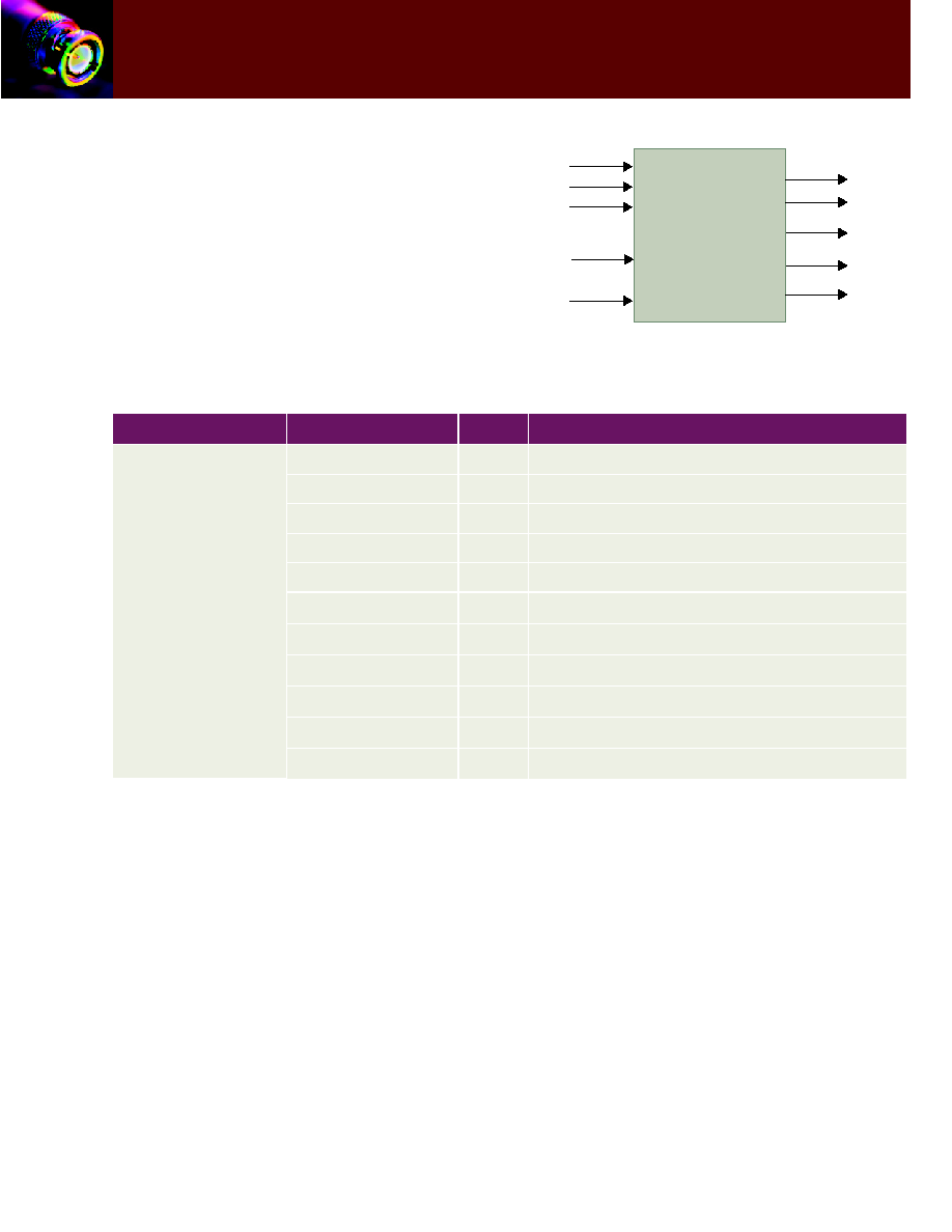
PIN / PORT DESCRIPTION
Table 1 describes
the input and output ports (shown graphically in Figure 2) of
the CS3311 Convolutional Encoder. Unless otherwise stated,
all signals are active high and bit (0) is the least significant bit.
Figure 2: CS3311 Core Pinouts
DVALI
DIN
BLKSTARTI
CLK
BLKSTOPI
QOUT
BLKSTARTO
DVALO
CS3311
BLKSTOPO
IOUT
Table 1: CS3311 - Convolutional Encoder Interface Signal Definitions
Section
Name
Type
Function
Encoder
I/O
Pins
DIN
I
Data Input
CLK
I
Clock
RESETN
I
Asynchronous Reset (Active Low)
DVALI
I
Data Valid In
BLKSTARTI
I
Block Start (Block Mode Only)
BLKSTOPI
I
Block Stop (Block Mode Only)
QOUT
O
Data Output Bit on Q channel
IOUT
O
Data Output Bit on I channel
DVALO
O
Data Valid Out
BLKSTARTO
O
Data Start Out
BLKSTOPO
O
Block Stop Out
3
TM
CONVOLUTIONAL CODES FOR ERROR
CORRECTION
Convolutional error-correction capabilities result from
outputs that depend on past data values. Each coded bit is
generated by convolving the input bit with the previous
uncoded bits. Convolving a signal with itself adds a level of
dependence on the past values. This mechanism provides the
ability to correct (to a certain level) a signal that has been
corrupted with noise such as Additive White Gaussian Noise
(AWGN). Data that is convolutionally encoded can be
decoded through knowledge of the possible state transitions,
created from the dependence of the current symbol on past
data.
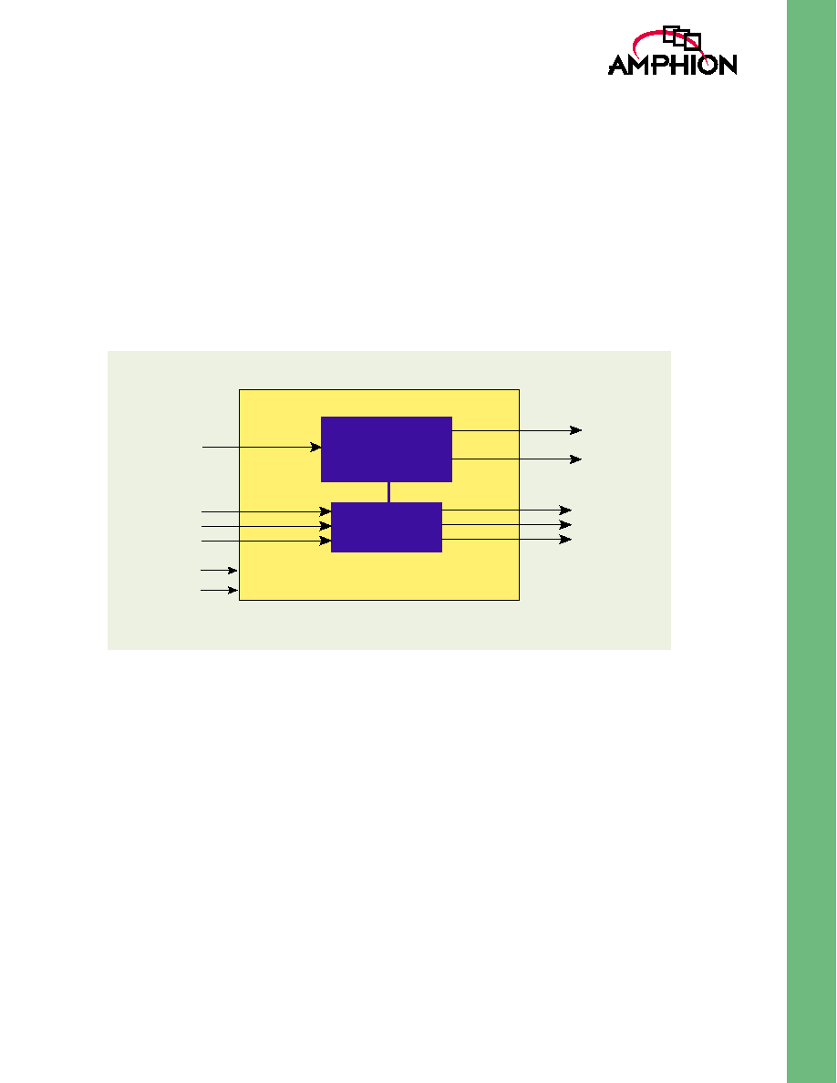
CS3311 FUNCTIONAL DESCRIPTION
The CS3311 core is a highly integrated Convolutional Encoder
suitable for a wide range of reliable communication
applications. The CS3311 Encoder operates in Viterbi mode
and can be used in power-limited applications. The block
diagram in Figure 3 shows the main functional blocks and
interfaces that have been identified for the Convolutional
Encoder. Internally the encoder comprises 2 individual blocks:
Convolutional Encoder block and Control Logic block.
Figure 3: CS3311 Overview Diagram
DIN
RESETN
Rate 1/2
Convolutional
Encoder
Control
Logic
BLKENDI
BLKSTARTI
DVALI
CLK
BLKENDO
BLKSTARTO
DVALO
IOUT
QOUT
4
CS3311
Convolutional Encoder
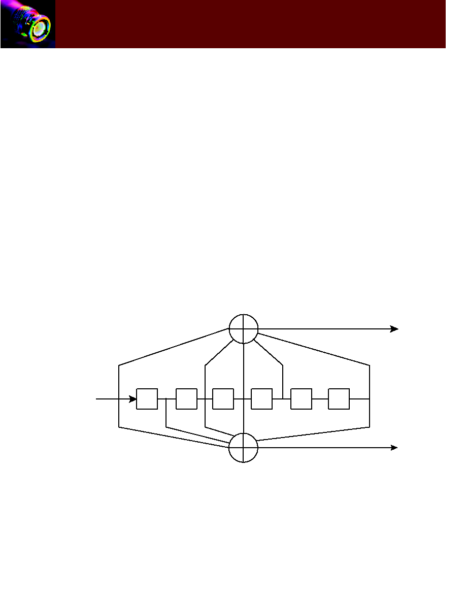
RATE 1/2 CONVOLUTIONAL ENCODER
BLOCK
Figure 4 shows a block diagram of an industry standard
Convolutional Encoder with the constraint length of 7 (k=7).
The generator polynomials for Rate 1/2 are:
�
G (0) = 171 (Octal)
�
G (1) = 133 (Octal)
CONTROL LOGIC BLOCK
This block controls the operation of CS3311. It sets DVALO,
BLKSTARTO and BLKSTOPO according to how DVALI,
BSTARTI and BLKENDI are set.
The BLKSTARTI, BLKENDI and DVALI inputs are used to
enable / disable the core. BLKSTARTI and BLKENDI signals
are only recognized if they are accompanied by a high signal
value on the DVALI input. A further condition on the
BLKENDI signal is that it can only be associated with a valid
BLKSTARTI signal. For example, BLKENDI will only take
effect if a valid BLKSTARTI signal has previously been
clocked into the core.
The beginning of a new block is recognized by the CS3311,
when BLKSTARTI is asserted high and clocked into the core,
accompanied by assertion of DVALI signal. Therefore, the
core will be enabled and prepared for fresh input data. One
clock cycle later DVALO and BLKSTARTO will be set high.
BLKSTARTO will remain high for one clock cycle while
DVALO will remain high as long as DVALI signal is set. The
end of the block is recognized by CS3311, when a valid
BLKENDI signal is subsequently clocked into the core. Six
zeros are placed on the internal data lines to flush the
Convolutional Encoder block such that it is forced into the all-
zero state. This "force-to-zero" mechanism is also utilized by
the decoder (CS3411). Nine clock cycles after the assertion of
BLENDI signal DVALO is cleared. QOUT and IOUT will be
invalid when DVALO goes low. If the DVALI input is de-
asserted while the core is being flushed, the core remains
enabled until the Convolutional Encode block is completely
flushed. BLKSTOPO will be set for the last clock cycle that
DVALO is set.
A valid BLKSTARTI signal will at any time clear the core. If
DVALI goes low during a block (apart from the case where the
core is being flushed) then the core will be disabled and
DVALO signals will go low after one clock cycle. The core will
be enabled once DVALI goes high again.
Figure 4: Block diagram of Implementation of Rate 1/2 Convolutional Encoder
DIN
IOUT
G0
QOUT
G1
5
TM
CORE OPERATION
The CS3311 operates in Viterbi Mode. All registers are
updated on a rising clock edge and the reset is active low.
The DIN signal is the only data input required. Rate 1/2 is
obtained directly from the Convolutional Encoder block and
is output on IOUT and QOUT. Other rates may be obtained
from external puncturing.
A high value on BLKSTARTI indicates the beginning of a
block of data and will clear the core. After one clock cycle,
BLKSTARTO will go high for one clock period. DVALO will
simultaneously go high and will remain high until the
Convolutional Encoder has been cleared by a BLKENDI
signal.
BLKENDI signal goes high to indicate the end of a block.
When an end of block is detected zeros are sequentially
inserted into the Convolutional Encoder block to clear it.
DVALO goes low once the Convolutional Encoder block is
clear. BLKSTOPO goes high during the last clock period that
DVALO is high.
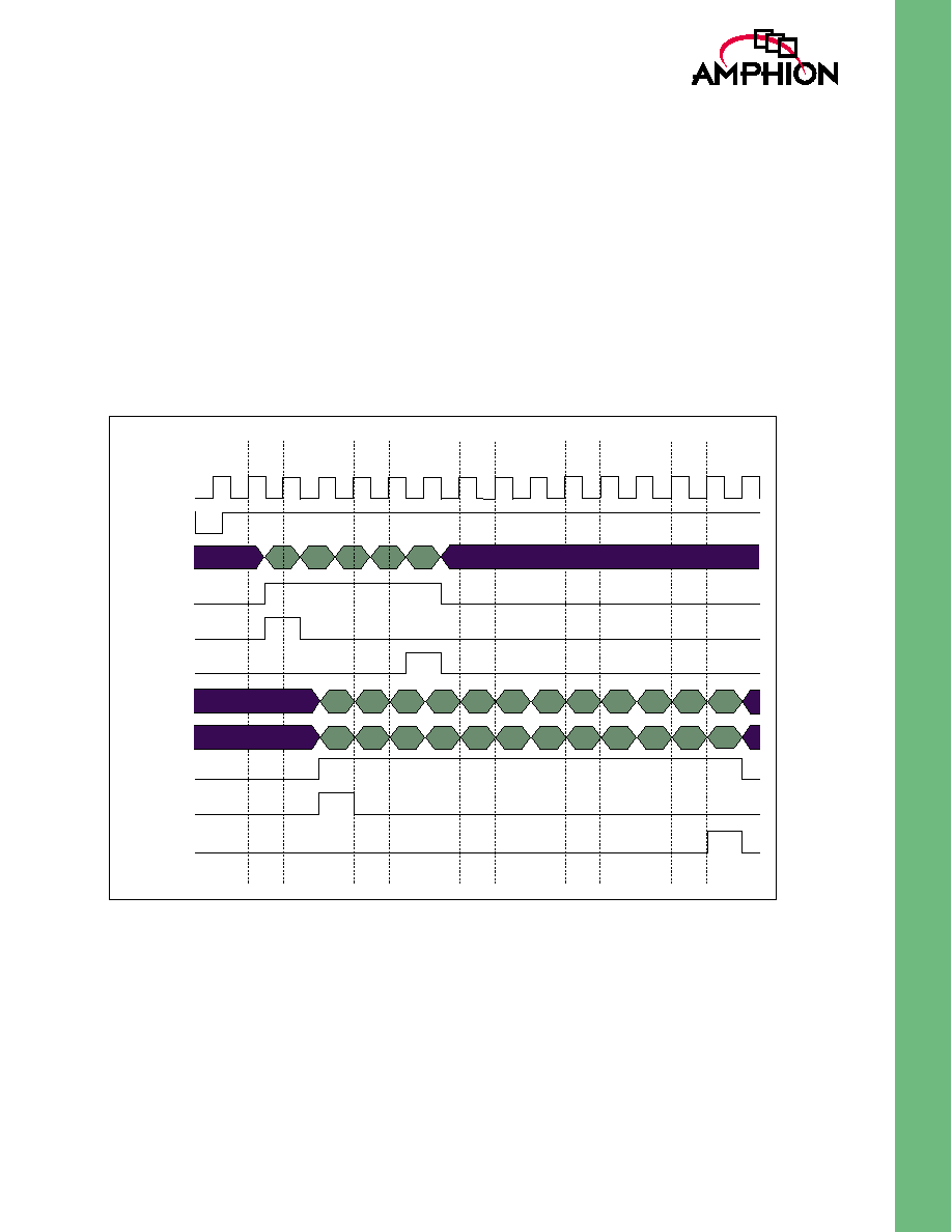
CS3311 I/O TIMING DIAGRAMS
Figure 5 illustrates typical waveforms for the CS3311
Convolutional Encoder.
Figure 5: CS3311 Functional Timing Characteristics
CLK
RESETN
DIN
DVALI
BLKSTARTI
BLKENDI
DOUT1
DOUT0
DVALO
BLKSTARTO
BLKSTOPO