 | –≠–ª–µ–∫—Ç—Ä–æ–Ω–Ω—ã–π –∫–æ–º–ø–æ–Ω–µ–Ω—Ç: CS3710 | –°–∫–∞—á–∞—Ç—å:  PDF PDF  ZIP ZIP |
TM
Virtual Components for the Converging World
Amphion continues to expand its family of application-specific cores
1
See http://www.amphion.com for a current list of products
CS3710
32 QAM Modulator
The CS3710 32 QAM modulator core provides a complete baseband solution for broadband data transmission.
This application specific silicon core has been developed to provide an efficient and highly optimized solution
for wireless data networks. Combined with the CS3810 32 QAM demodulator core, data transmission speeds of
up to 155Mbps can be achieved at low error rates. The CS3710 is suited for application areas such as point to
point WLAN, Metropolitan Area Network, wireless VPN and other data, voice and video applications. This core
combines easily with the CS5200 series of AES cryptography cores to create secure high speed data links.
The CS3710 can accept a continuous stream of user input data and modulate it to a spectrally shaped 32QAM
constellation, suitable for wireless transmission. Error resilience is provided using a concatenated forward error
correction (FEC) scheme including Reed-Solomon coding, interleaving and convolutional coding to provide low
BER at the receiver. The core parameters may be set using an integrated microprocessor interface. This same
interface may also be used to read back the core parameter settings at any particular time.
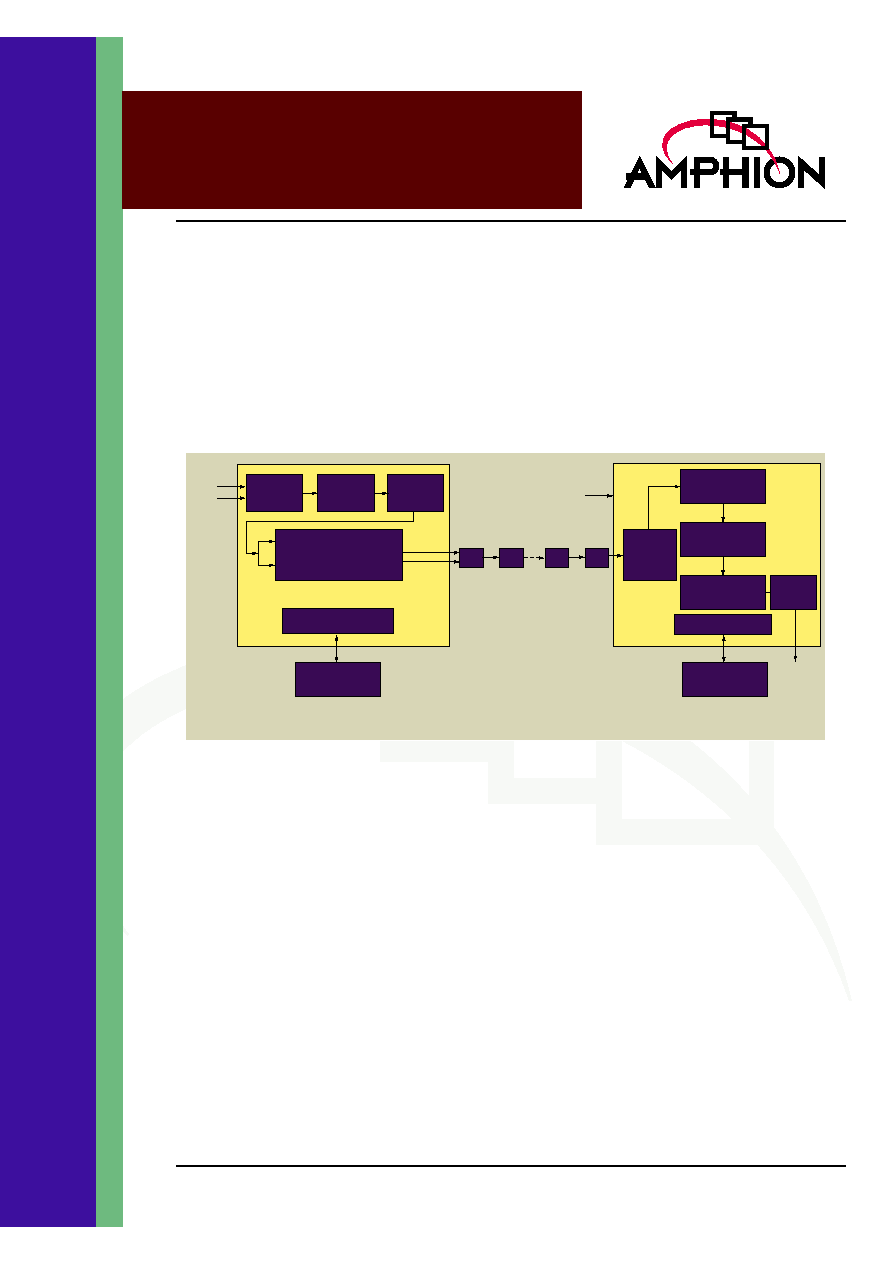
Figure 1: Block Diagram of CS3710/CS3810 Broadband Wireless Modulation/Demodulation Cores
Data
Encoding
Error
Protection
Mapping
Spectral Shaping
Control Registers
TXI_OUT
TXQ_OUT
Data Input
Test Input
Controller/
Processor
CS3710 Broadband Wireless Modulator Core
ADC
Timing/symbol
recovery
Decode &
Synchronisation
Error Correction
& Recovery
Control Registers
Filtering
Controller/
Processor
Test Input
Data Out
CS3810 Broadband Wireless Demodulator Core
Output
formatter
RF
RF
DAC
FEATURES
Fully integrated modulator supports
transmission of voice, data and video up to
155Mbps
Continuous mode operation
32 QAM modulation
Available on FPGA implementation
Parallel microprocessor interface (Motorola
style)
Built in PN data generator
Built in SSB tone generator
Concatenated Convolutional and Reed
Solomon coded error protection
Separate I-Q outputs
Transmitter clock may be slaved to CS3810
32 QAM demodulator recovered clock
Internal byte clock to symbol clock
conversion
APPLICATIONS
Wireless Metropolitan Area Network
Wireless LAN
Secure wireless VPN
Broadband voice, data and video
transmission

2
CS3710
32 QAM Modulator
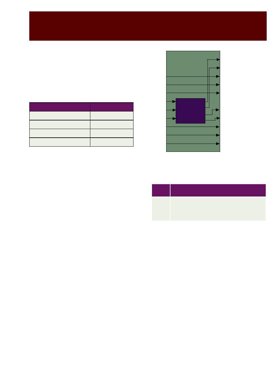
INPUT/OUTPUT DESCRIPTION
Table 1 describes the input and output ports (shown
graphically in Figure 2) of the CS3710 modular core. Unless
otherwise stated, all signals are active high and bit(0) is the
least significant bit.
The internal architecture of the Core is illustrated in Figure 3.
It comprises spectral error protection, synch insertion and
channel coding circuitry. The core is controlled by a bank of
registers accessed through a microprocessor interface.
Figure 2: CS3710 Symbol
Figure 3: Block Diagram of the CS3710
TXDATA[7:0]
TXSYNC
RXDATA[7:0]
RXSYNC
TXUSRCLK
CLK
RESET
TXRX
PRBS
SSBEnab
BPTCM
TWOSCOM
CS3710
32-QAM modulator
TXI_OUT[9:0]
TXQ_OUT[9:0]
TX_Valid
TXFULL
TXEMPTY
TCM_I[4:0]
TCM_Q[4:0]
TCM_Valid
Input
Data
Control Register Bank
Synchro-
nization
Scrambler
RS
Encoder
Unique
Word
Insertion
Inter-
leaver
TCM
SSB
Map
SRRC
filter
Output
PRBS
Table 1: CS3710 32 QAM Modulator Interface Signal Descriptions
Name
I/O
Description
GENERAL I/OS
CLK
I
Clock at 2 x Symbol Rate
RESET
I
Active low asynchronous reset signal ≠ applied to all registers
MODULATOR USER INPUT
TXDATA[7:0]
I
Byte wide data input
TXUSRCLK
I
Byte clock input ≠ rising edge active
TXSYNC
I
Indicates first byte in Frame ≠ asserted during the TXUSRCLK cycle before the
first byte of a frame is on the TXDATA port
MODULATOR CONTROL PIN
TXRX
I
Input data selector: 1: TXDATA or PRBS;
0: RXDATA
PRBS
I
Pseudo Random Binary Sequence generator enable signal, TXRX=1 and
PRBS=1 enable PRBS sequence
SSBEnab
I
High to enable SSB (Single Side Band) stream
BPTCM
I
High to by pass TCM (Trellis Code Modulator) encoder

3
TM
FUNCTIONAL OPERATION
SYSTEM CLOCKS
Each sub-block function in Figure 3 is described in this
section. The CS3710 has two clock signals, namely,
TXUSRCLK and CLK. These two clocks are linked by the
symbol rate, which is 120/63 or 12/7 times TXUSRCLK. The
Input data stream is block based and synchronised by
TXUSRCLK with each block containing 224 bytes. The output
stream consists of the shaped and filtered I and Q samples and
TCM_I and TCM_Q symbols synchronised by CLK.
PRBS
Functions of the PRBS sub-block are:
∑
Register input data TXDATA, RXDATA and all control
signals
∑
Multiplex input data according to input control pin
configuration
Input data TXDATA and RXDATA (loopback mode) are
registered using the TXUSRCLK. The data is multiplexed to
feed BlkSync according to the configuration of the Core. When
TXRX is High, and PRBS is low, the TXDATA is selected,
otherwise if the PRBS is High, the PRBS sequence is selected.
In all cases, the SSB data is generated if SSB is High.
SCRAMBLER
Maximal-length 20 bit scrambler, generating 2
20
-1 patterns,
which follows the IntelSat IESS-308 standard. Generator
polynomial used is:
There is one cycle delay in this module.
REED SOLOMON ENCODER
The Reed-Solomon encoding algorithm is implemented
according to following parameters:
∑ Galois field GF(
).
∑ Primitive polynomial:
∑ Generator polynomial:
The RS encoder supports codewords of the format (240,224).
The 16 parity symbols calculated by the RS encoder are added
to the end of the information bytes that were input. The start
of frame sync flag is also piped through with the same latency
as the data to be fed onto the next module in the chain.
TWOSCOM
I
Output Format: 1: 2's complement, 0: Offset binary
MODULATOR LOOP BACK INPUT
RXDATA[7:0]
I
Byte wide loop back data input
RXSYNC
I
Indicates first byte in Frame ≠ asserted during the TXUSRCLK cycle before the
first byte of a frame is on the loop back RXDATA port
MODULATOR OUTPUT INTERFACE
TXI_OUT[9:0]
O
Output symbol data to I-rail DAC ≠ clocked out on the rising edge of CLK
TXQ_OUT[9:0]
O
Output symbol data to Q-rail DAC ≠ clocked out on the rising edge of CLK
TX_Valid
O
Output data valid indicator signal
TXFULL
O
Mapper FIFO full indicator
TXEMPTY
O
Mapper FIFO empty indicator
TCM_I[4:0]
O
Output TCM/QAM32 symbol data to I-rail≠ clocked out on the rising edge of CLK
TCM_Q[4:0]
O
Output TCM/QAM32 symbol data to Q-rail≠ clocked out on the rising edge of CLK
TCM_Valid
O
Output TCM/QAM32 symbol valid indicator signal
Table 1: CS3710 32 QAM Modulator Interface Signal Descriptions
Name
I/O
Description
p X
( )
1 X
3
X
20
+
+
=
2
8
m X
( )
1 X
2
X
3
X
4
X
+
+
+
8
+
=
g X
( )
X
0
+
(
) X
1
+
(
)... X
2T 1
≠
+
(
)
=
4
CS3710
32 QAM Modulator
UNIQUE WORD INSERTION
The insertion of unique word information for receiver frame
synchronization follows the scheme outlined in the Intelsat
standard IESS-308. The insertion of the unique word occurs
every 16 RS codewords which makes up a superframe. It is
assumed that the first frame input after reset is the first block
of a superframe. The unique word is a 4-byte value with 2
bytes over-writing the final 2 parity bytes in the first 2
successive Reed-Solomon codewords of a superframe. .
INTERLEAVER
The interleaver follows the Intelsat IESS308 scheme, which
involves a block interleaver with a depth of 4 frames and an
offset between each frame of 60 bytes. That is, 4 consecutive
frames are written into the interleaver in row order, but with
successive frames offset from each other by 60 byte locations.
The data is then read out in column order.
TCM ENCODER
The TCM encoder is based on a rate Ω convolutional encoder
with puncture rate 9/10 as shown in Figure 4. The punctured
TCM encoded symbols are then mapped to the 32 QAM
constellation. The TCM coding is performed directly on the
byte wide data that is input from the interleaver. The output
from the TCM encoder is in the form of 5 bit symbols which
are further coded to 3-bit words passed to the spectral shaping
filter.
Figure 4: Encoder for Rate 9/10 Trellis Code for 32-QAM
(with puncturing)
The puncture patterns for 9/10 puncture rates are defined
below.
SSB AND MAPPER
The SSBMap sub-block performs the following functions:
∑
Inserts TCM coded symbols into a transmit FIFO for
resampling
∑
Codes re-sampled TCM symbols to 3-bit I-Q samples for
RRC filter input
∑
Replaces I-Q samples with SSB pattern when SSB is
enabled
The output from the TCM encoder is pushed into the FIFO
when it is valid. The symbols from the FIFO are further coded
to 3-bit I-output and Q-output according to the 32-QAM.
When SSB is enabled, the SSB pattern, a sine wave in the
I-channel and a cosine in the Q-channel, replaces the symbol
from the FIFO and is fed to the transmit filter. This drives the
filter full scale, and hence the SSB stream is re-scaled to the
maximal amplitude of the 32 QAM constellation.
Unique Word Mnemonics
Value in Hex
Unique word 3
0x66
Unique word 2
0xBE
Unique word 1
0x0F
Unique word 0
0x5A
Code
Rate
Puncture Pattern (X marks a punctured bit)
9/10
1 1
Applied to the MSB (bit 8) of a 9-bit input
symbol
1 X X 1 Applied to bit 4 and bit 3 of a 9-bit input
symbol
Rate 3/4 punctured
encoder
Bit 7
Bit 6
Bit 5
Bit 8
Bit 2
Bit 1
Bit 0
Bit 4
Bit 3
Bit 2
Bit 1
Bit 0
Bit 4
Bit 3
Bit 2
Bit 1
Bit 0
Bit 4
Bit 3
First TCM symbol
(unpunctured)
Second TCM symbol
(punctured)
5
TM
SRRC FILTER
The SRRC (Square Root Raised Cosine) Filter consists of two
multiple-rate filters performing the shaping and filtering
function for the I-Q samples. Note that the filter is not
normalised, as this is to be considered in the hardware.
The inputs to the filter bank are:
∑
Re-sampled TCM data further coded to 3-bit I-Q samples,
The SRRC filter is a hardware specific filter, which computes
one output sample every clock (CLK) cycle using a look up
table with the coefficients specified by the coefficients selector.
The filter coefficients are obtained from a square rooted raised
cosine filter, and further decimation to two sets of polyphase
filters. The filter coefficients are quantified to 12-bits to make
full use of the fixed point dynamic range. The coefficients
selector will select coefficient set 0 whenever a new sample is
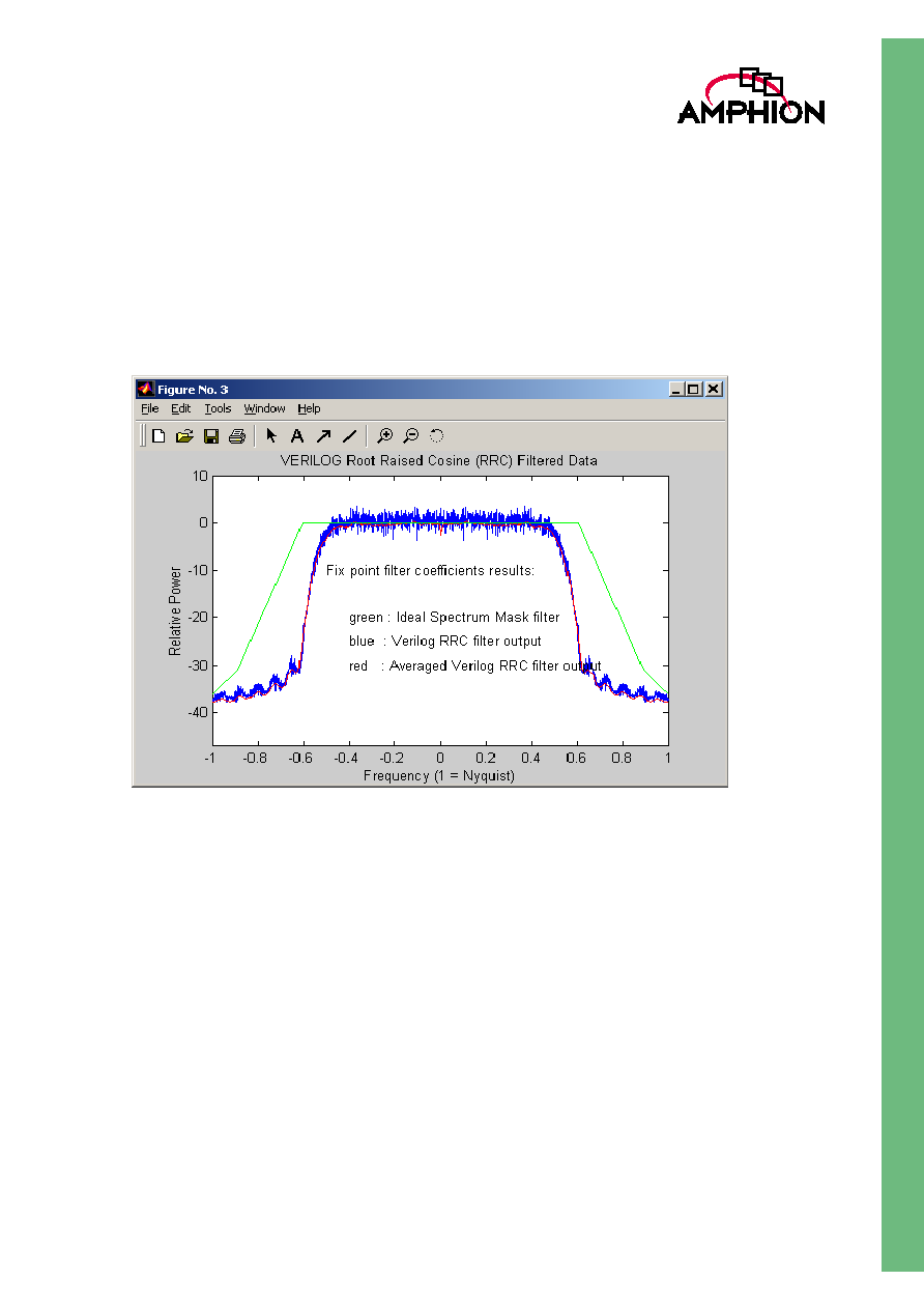
fed into the SRRC filter. The spectral shaping performance of
this filter is illustrated in Figure 5.
Figure 5: Spectrum of Filter Output Data