TM
Virtual Components for the Converging World
Amphion continues to expand its family of application-specific cores
1
See http://www.amphion.com for a current list of products
CS6100
Motion JPEG Encoder
The CS6100 Motion JPEG (M-JPEG) Encoder is a highly integrated application specific silicon core for leading-
edge image compression and transmission applications. Its high performance is capable of sustaining data rates
of over 285 Msamples/sec
1
� delivering full motion, full color video images up to 6 megapixels
2
. Equally suited to
low-power, battery-operated consumer electronics as it is to high-end professional video equipment and office
automation solutions, the CS6100 delivers the optimal performance and low power consumption that only an
expertly tuned component can provide. The CS6100 is available in both ASIC and programmable logic versions
that have been handcrafted by Amphion to deliver high performance with low-power and minimal silicon area.
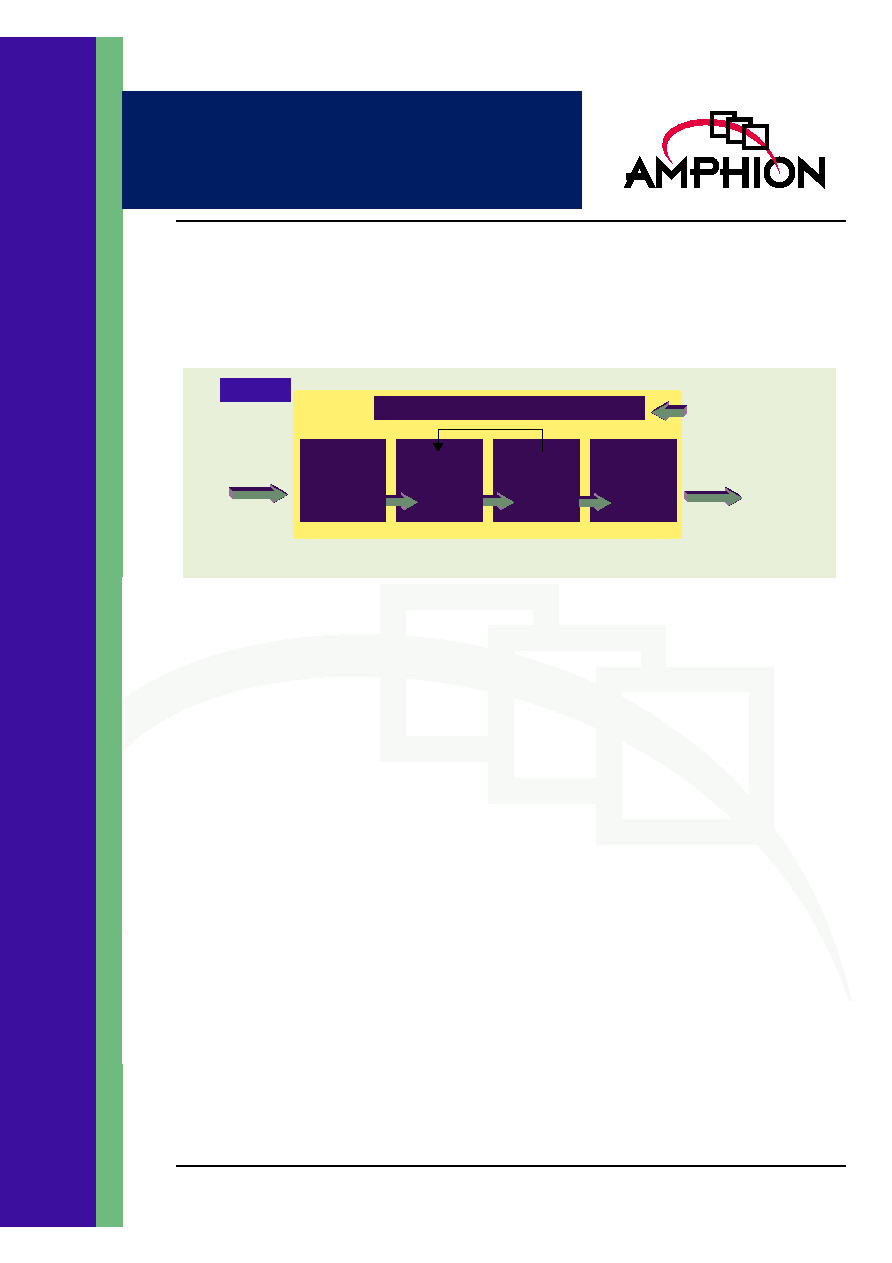
Figure 1: CS6100 Overview Diagram
Image
Source
Sample
Data
Configuration & Control Interface
Host Processor
(or) State Machine
JPEG
Stream
CS6100
Frequency
(DCT)
Transform
& Coefficient
Quantization
Bit Rate
Control
(Patent Pending)
Run Length
& Variable
Length
Encoder
JPEG
Stream
Generator
The highly integrated CS6100 does not require host processor intervention during the encoding process. Once configured
the CS6100 autonomously and continuously encodes raw sample data into fully ISO/IEC 10918-1 compliant data streams.
FEATURES
High Performance >285 Msamples/s Encoding
Capability
1
-
Single sample per clock cycle processing
Low Power
-
Fully synchronous operation
-
Zero power standby mode
3
Fully Compliant with Baseline JPEG Standard
ISO/IEC 10918-1/2
Autonomous Operation
-
Sample data in, JPEG stream out
-
No host processor intervention required
Dual Mode Operation
-
Automatic continuous streaming mode
-
Variable image mode
Ease of Integration
-
Targeted netlist
-
No code memory required
Advanced Image Coding Features
-
Four programmable quantization tables
-
Four programmable Huffman Coding Tables
-
Bit-rate control (patent pending) for dynamic
output rate stabilization
3
-
On-board configuration data memory
Ease of Configuration
-
State machine: synchronous handshake inter-
face
-
Host Processor: memory mapped interface
-
capability
-
Support for standard and abbreviated JPEG
configuration formats
-
Automatic configure-once encode-many oper-
ation
Flexible Image Source Input
-
Image Size up to 65,535 by 65,535 (4.3
Gigapixel)
-
All color formats including: RGB, YUV,
YCbCr, CMYK and Grayscale
-
Horizontal and vertical sub-sampled input
supported
-
Interleaved and non-interleaved scans sup-
ported
KEY METRICS
Logic:
70K gates (std cell)
Memory:
2.7 Kbytes
Maximum Frequency:
285 MHz
APPLICATIONS
Digital Still Cameras
Remote Digital Video
Video Production
Office Automation Equipment
Handheld Scanners
1
Performance is dependent on the silicon process and libraries selected. 285MHz operation is representative of 130 nm silicon using standard cell libraries.
2
30 frame/sec, 24-bit color images with three components in 4:2:0 format
3
When implemented with fully static SRAM blocks w/power-down
2
CS6100
Motion JPEG Encoder
CS6100 FUNCTIONAL DESCRIPTION
The CS6100 application specific silicon core is a highly
integrated JPEG encoder suitable for a wide range of imaging
applications. Designed for continuous data flow � one image
sample per clock cycle � without host microprocessor
intervention, the CS6100 can address the most demanding
frame-based video compression applications. In addition, it is
ideal for low power applications where � once configured � it
can be stopped and restarted instantaneously. The fully
synchronous, highly autonomous design requires no software
overhead. A rich feature set includes an adaptive-feedback bit
rate control (BRC) mechanism (patent pending), multiple real-
time selectable coding tables, manual and automatic
configuration modes and on-board configuration memory.
The CS6100 is a powerful and flexible JPEG encoding solution.
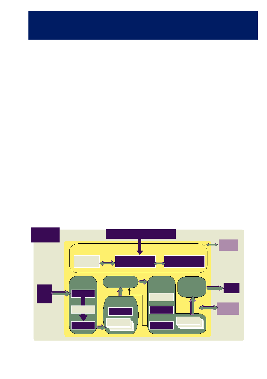
FUNCTIONAL BLOCK OVERVIEW
Image source data in any color space format is input to the
CS6100 in block data format. The CS6100 can process up to
255 color components in an unlimited number of scans per
image (each scan can contain between one and four color
components). The image samples are compressed according
to user-definable quantization and Huffman coding
parameters. Built-in bit rate control circuitry is selectively
employed for bandwidth constrained applications. The
CS6100 outputs an ISO/IEC 10918-1 compliant data stream.
Separate configuration, parameter extraction and test access
ports provide high visibility and flexible control for ease of
integration of the CS6100 into the complete system-level ASIC
design.
FREQUENCY TRANSFORM
The frequency transform (FT) unit accepts 64-byte (8 x 8)
blocks of image sample data (raster order within the block)
and converts these to 8 x 8 blocks of frequency coefficients
using a 2D discrete cosine transform (DCT) architecture. This
is implemented as two, 1D DCT operations, with the
intermediate results being stored in the dual-port transpose
memory (TRMem) buffer. The architecture of the FT unit
allows for continuous one-sample per cycle operation with a
latency between first sample in and first coefficient out of 72
clock cycles. The 11-bit coefficient data is streamed out from
the FT unit for direct input to the quantization unit.
COEFFICIENT QUANTIZATION
The coefficient quantization unit (QT) divides each of the 64
DCT coefficients in an image sample block by the values
specified in one of the four quantization tables stored in
QTMem (each table contains 64 entries, one per coefficient).
The purpose of the quantization process is to reduce the
amplitude of the coefficients and to increase the number of
zero value coefficients in preparation for the latter stages of
the JPEG encoding process. The 11-bit DCT data is loaded into
QT directly from the FT in column major order. The
QT unit quantizes one sample per clock cycle with a latency
between the first sample in and the first sample out of three
clock cycles.
Figure 2: CS6100 JPEG Encoder Block Diagram
Host Processor (or) State Machine
Parameter
Extraction
Config Mem
Auto Parser
Code Control
Configuration & Control Interface
CS6100
JPEG
Stream
Test
Access Port
HTMem
JPEG
Data Stream
Generator
(DSG)
Variable Length
Encoder
(RLE) & (HUFF)
ZZMem
Run Length
Encoder
Huffman
Coder
Adaptive Bit Rate
Control (BRC)
Coefficient
Quantization (QT)
Divider
QTMem
Frequency
Transform
(FT)
DCT
Image
Source
Sample
Data
TRMem
DCT

3
TM
Figure 3: Bit Rate Control Illustration
ADAPTIVE BIT RATE CONTROL
The adaptive bit rate control unit (BRC) applies a coefficient
thresholding technique for ensuring that the compressed
image size does not exceed a user defined bandwidth budget.
This particular feature of the CS6100 is essential for
applications where the JPEG stream output from the CS6100 is
to be transmitted over a bandwidth-constrained data channel.
The BRC tracks the byte-count growth during the
compression of an image via feedback from the Huffman
encoder in the VLE block. The BRC adapts dynamically as the
total image is processed, applying different rules to selectively
remove (zero-out) coefficients in order to converge the actual
compressed image size and the ideal size. Further details on
the BRC mechanism are provided in the CS6100 Databook.
The CS6100 BRC features are a significant advancement over
the requirements set forth in the JPEG standard, yet the
resultant output stream is 100% compliant with the standard
and can be decoded by any standard-compliant JPEG decoder.
VARIABLE LENGTH CODER
The variable length encoding unit (VLE) consists of both the
run length encoding unit (RLE) and the Huffman encoder
(HUFF). Data output by the BRC is buffered in the ZigZag
Memory (ZZMem) then loaded into the run length encoder
(RLE) unit. The RLE compresses the data stream by
converting the data to Run-Size pair data bytes. Huffman
encoding techniques are then applied to the stream of Run-
Size pairs to replace them with a corresponding code read
from a look-up table stored in the Huffman Table memory
(HTMem). Huffman codes are designed to be uniquely
identifiable yet minimize the number of bits required to store
all the Run-Size codes for an image. The CS6100 can store four
user-defined Huffman Tables, two for DC coefficients and two
for AC coefficients, the DC and AC coefficients being
Huffman encoded separately. The compression produced by
the VLE is data dependent thus latency can vary from one
block to the next.
DATA STREAM GENERATOR
The data stream generator unit (DSG) accepts the Huffman
encoded data stream from the VLE and packs the variable
length words into double-byte words. The double-byte words
are output over the JPEG output bus (JpgOut) when requested
by the external system. Additionally, the DSG outputs JPEG
file header information according to the parameters set during
configuration and under control of the JPEG mask control
port (JpgMask). The DSG also provides feedback to the BRC
to enable the dynamic control of the compression should this
feature be selected by the system. The latency of the DSG is
variable and depends on the data received from the VLE.
When the last data for a frame is received from the VLE, the
double-byte word is padded out and is immediately available
for output.
CONFIGURATION
& CONTROL INTERFACE
The configuration and control interface unit (CCI) includes an
AutoParser that interprets configuration data, a configuration
memory (ConfigMem) for storing the full configuration
stream for later use as part of the JPEG output stream, and a
code control state machine (CodCtrl) that manages the
operation of the CS6100.
Adaptive Bit Rate Control
Coefficient Thresholding Mechanism
Example Plot of DCT
Coefficients for and 8x8 block
Zero Sequences produced
Sub-threshold region
(Blanking region)
DCT Coefficient Index (zigzag order)
01
16
32
63
max
Quantized
DCT
Coefficient
Value
3-region
variable
blanking
thresholds
Tc
Tb
Ta
0
4
CS6100
Motion JPEG Encoder
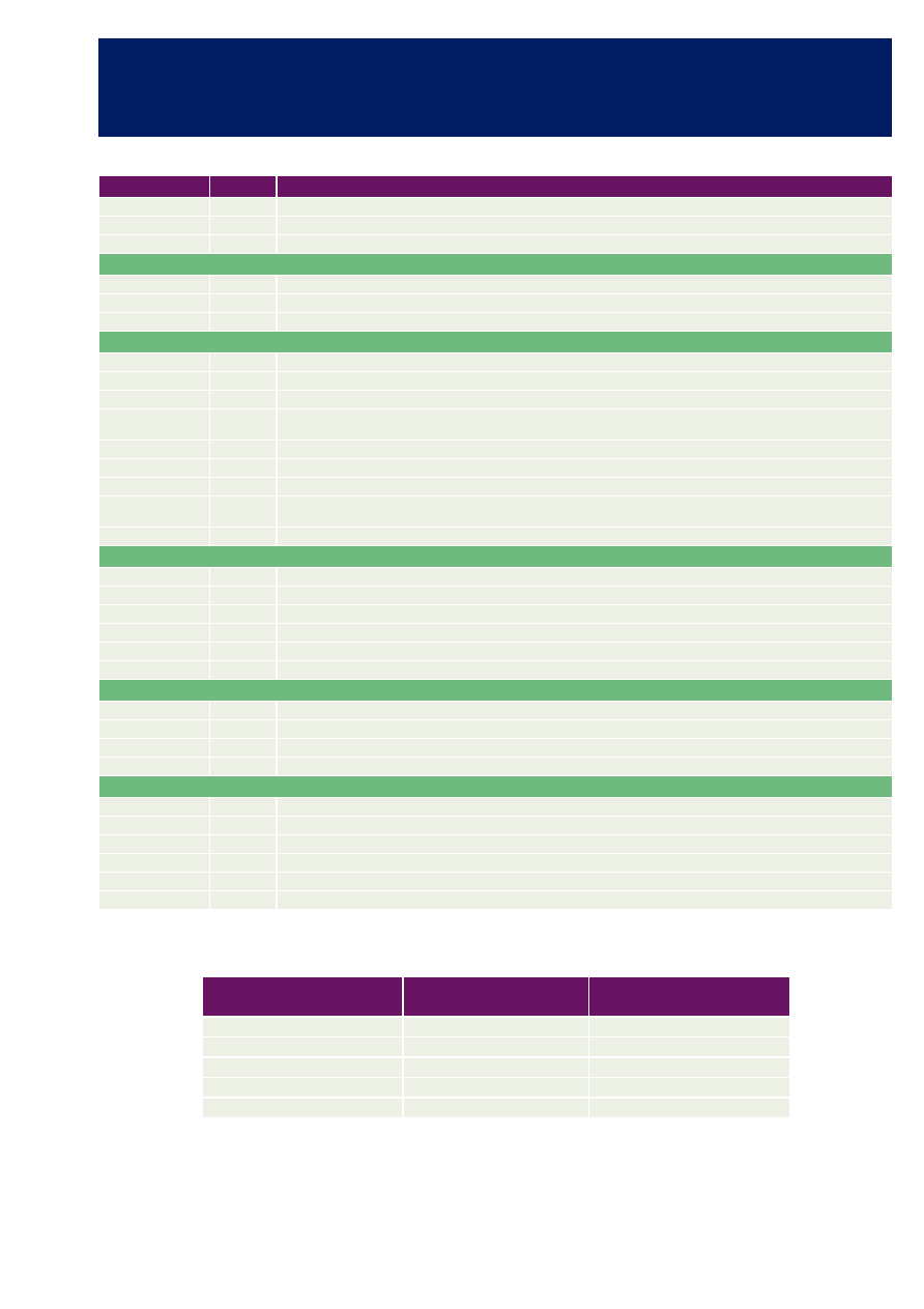
MEMORY ELEMENTS
Table 1: I/O Signal Description
Name
Type
Description
CLK
Input
Clock - rising edge active
RSTn
Input
Asynchronous reset (power-on reset)
CLR
Input
Synchronous reset
CONFIGURATION PORT
CfgIn[7:0]
Input
Configuration input port
CfgRdy
Output
Indicates that the CS6100 is ready to accept configuration data
CfgStrb
Input
Configuration input strobe
STATUS & CONTROL
AutoAvail
Output
Indicates that automatic mode may be used
AutoStart
Input
Causes the CS6100 to enter AutoEncode state
InitProg
Output
Indicates that the CS6100 is currently initializing its internal memories
TblDef[7:0]
Output
Indicates number of tables defined. Bits[7:4] indicate Huffman Tables. Bits [3:0] indicate quantization tables, 1
bit/table
PValue[15:0]
Output
Encoding parameter bus
PType[3:0]
Input
Signal specifying parameters to be placed on port PValue
PValid
Output
Indicates valid coding parameter
SigSOS
Output
Indicates that a SOS segment has been input via CfgIn or has been read from the configuration memory and the
CS6100 is about to start encoding a scan
EncFlags[7:0]
Output
CS6100 internal status and error flag status register
JPEG STREAM PORT
JpgMask[4:0]
Input
JpgOut stream configuration port
JpgOut[15:0]
Output
JPEG output stream
JpgAvail
Output
Indicates that valid data is available on JpgOut
JpgNext
Input
Informs core to place next 16-bit word of output data onto JpgOut. Data held if JpgNext not asserted
JpgLast
Output
Indicates that the data on port JpgOut is the last one of an encoded JPEG data stream
JpgEnd
Output
Indicates that the last data of the encoded JPEG data stream has been output on port JpgOut
DATA SAMPLE INPUT PORT
PixIn[7:0]
Input
Sample data input port
PixStrb
Input
Indicates the first pixel of an 8x8 block
PixRdy
Output
Indicates that the CS6100 is ready to accept data
ScanEnd
Input
Indicates that the current MCU row is the last one of the scan
TEST PORT
TType
Input
Test type selector
TSOS
Output
Marks the first value in the first 8x8-output block of test data
TSOB
Output
Marks the first value in each 8x8-output block of test data
TData [10:0]
Output
11-bit output test data port � displays DCT coefficients or quantized coefficients
TValid
Output
Indicates valid test data output
TestEn
Input
Causes memories to be bypassed for test purposes
Table 2: Memory BLock Size Information
MEMORY BLOCK
CONFIGURATION
(WORDS x BITS
PORTS
Huffman Tables (HTMem)
384 x 20
Single Port, synchronous
Transpose Memory (TRMem)
64 x 15
Dual Port, synchronous
ZigZag Memory (ZZMem)
192 x 11
Dual Port, synchronous
Quantization Tables (QTMem)
512 x 8
Single Port, synchronous
Configuration Memory (CFMem)
840 x 8
Single Port, synchronous
5
TM
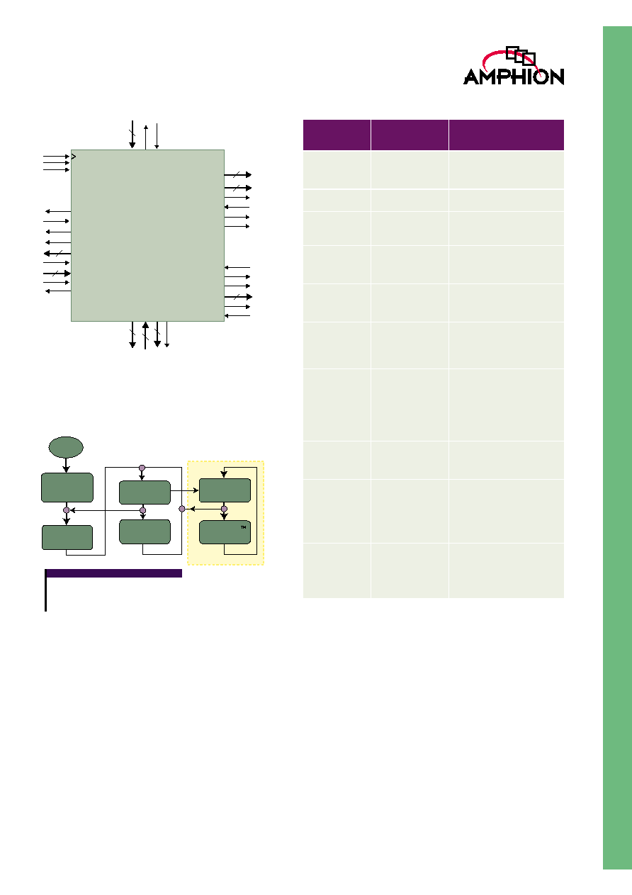
CS6100 SYMBOL & PIN DESCRIPTION
Figure 4: CS6100 Symbol
CS6100 OPERATION
The major operating modes and states of the CS6100 are
shown in Figure 5.
Figure 5: CS6100 Operation
CONFIGURATION OF THE CS6100
The CS6100 is configured via the Configuration Port using the
standard JPEG markers listed in Table 3. Configuration can be
performed either by a simple state machine, which streams
data into the configuration port, or by a host system
microprocessor. Refer to the CS6100 Databook for more
details on the configuration process and the configuration
memory.
Data presented to the Configuration Port is stored in the
configuration memory of the CS6100. A full (standard)
configuration is required after reset to load the quantization
and Huffman Tables. When variable image mode is utilized,
abbreviated configuration streams can be employed to control
compression of variable sized images or varying scans/image.
Examples of both the abbreviated configuration and standard
configuration streams are provided in the databook.
The CS6100 can also be configured to operate in automatic
mode without any further configuration required for each
image, therefore minimizing the interaction required from the
system.
JpgMask[4:0]
JpgOut[15:0]
JpgAvail
JpgNext
JpgLast
JpgEnd
5
16
11
TType
TSOS
TSOB
TData[10:0]
TValid
TestEn
PV
alid
EncFlags[7:0]
PT
ype[3:0]
PV
alue[15:0]
16
4
8
AutoAvail
PixRdy
PixStrb
PixIn[7:0]
ScanEnd
TblDef[7:0]
SigSOS
InitProg
AutoStart
8
8
CfgIn[7:0]
CfgRdy
CfgStrb
CLR
RSTn
CLK
8
Reset
Initialization
State
(384 Clock Cycles)
Configure State
Variable Image
Encode State
AUTOMODE
AutoAvail State
AutoEncode
State
Idle State
1
2
3
4
5
KEY
1 EOI input without CS6100 fully configured
2 SOS input and bit 4 of JPGMask asserted
3 EOI input with CS6100 fully configured
4 SOI input
5 AutoStart asserted
Table 3: JPEG Markers Supported for Configuration
MARKER
JPEG MARKER
NAME
DESCRIPTION
SOI
Start of Image
Start of image marker
0xFFD8 indicates the start of
a configuration stream
COM
Comment
Reserved for text fields
APPn
Application
segment, n=0-F
Reserved for application use
DQT
Define quantiza-
tion table(s)
Marker for input of quantiza-
tion tables. Up to 4 tables
may be defined.
DHT
Define Huffman
Table(s)
Marker for definition of the
Huffman Tables. Up to 4
tables may be defined
DRI
Define restart
interval
Set to zero by default, this
allows the image to be broken
up into independently
decodable segments
SOF(0)
Baseline frame
definition
Defines frame parameters
that apply to all scans within
the frame. Includes number
of components per frame,
sampling factors, and which
quantization table is to be
used by each component
EOI
End of image
End of image marker indi-
cates end of configuration
data
SOS
Start of scan
Defines the parameters
relating to each scan in the
frame, including the number
of components and the Huff-
man Tables to be associated
with each component
DNL
Define number
of lines
Used to redefine number
of lines in image for use with
ScanEnd signal. Main appli-
cation is in handheld scan-
ners