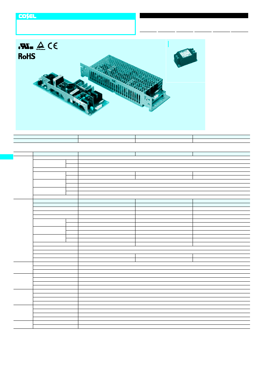
MODEL
LEP100F-24
LEP100F-36
LEP100F-48
DC OUTPUT
+24V 4.2(Peak 7)A
+36V 2.8(Peak 4.7)A
+48V 2.1(Peak 3.5)A
SPECIFICATIONS
MODEL
LEP100F-24
LEP100F-36
LEP100F-48
INPUT
VOLTAGE[V]
AC85 - 264 1
f
or DC 120 - 370
CURRENT[A]
ACIN 100V 1.4typ (Io=100%)
ACIN 200V 0.7typ (Io=100%)
FREQUENCY[Hz]
50/60 (47 - 63) or DC
EFFICIENCY[%]
ACIN 100V 81typ (Io=100%)
82typ (Io=100%)
83typ (Io=100%)
ACIN 200V 84typ (Io=100%)
85typ (Io=100%)
85typ (Io=100%)
POWER FACTOR
ACIN 100V 0.98typ (Io=100%)
ACIN 200V 0.93typ (Io=100%)
INRUSH CURRENT[A]
ACIN 100V 15typ (Io=100%) (At cold start) (Ta=25
C
)
ACIN 200V 30typ (Io=100%) (At cold start) (Ta=25
C
)
LEAKAGE CURRENT[mA]
0.75max (60Hz, According to IEC60950 and DEN-AN)
OUTPUT
VOLTAGE[V]
+24
+36
+48
CURRENT[A]
*
2
0 - 4.2 (Peak 7)
0 - 2.8 (Peak 4.7)
0 - 2.1 (Peak 3.5)
WATTAGE[W]
100.8 (Peak 168)
100.8 (Peak 169.2)
100.8 (Peak 168)
LINE REGULATION[mV]
48max
48max
48max
LOAD REGULATION[mV]
76max
90max
150max
RIPPLE[mVp-p]
0 to +50
C
*
3
120max
120max
150max
-10 - 0
C
*
3
160max
160max
300max
RIPPLE NOISE[mVp-p]
0 to +50
C
*
3
150max
150max
250max
-10 - 0
C
*
3
180max
180max
350max
TEMPERATURE REGULATION[mV]
0 to +50
C
120max
150max
240max
-10 to +50
C
145max
180max
300max
DRIFT[mV]
*
4
48max
48max
48max
START-UP TIME[ms]
500max (ACIN 100V, Io=100%)
HOLD-UP TIME[ms]
20typ (ACIN 100V, Io=100%)
OUTPUT VOLTAGE ADJUSTMENT RANGE[V]
21.4 - 26.4
26.4 - 39.6
39.6 - 52.8
OUTPUT VOLTAGE SETTING[V]
23.0 - 25.0
35.0 - 37.0
46.0 - 50.0
PROTECTION
CIRCUIT AND
OTHERS
OVERCURRENT PROTECTION
Works over 101% of peak current and recovers automatically
OVERVOLTAGE PROTECTION
Works at 115 - 140% of rating
REMOTE ON/OFF
Option (Refer to Instruction Manual)
ISOLATION
INPUT-OUTPUT
-
RC
*
5
AC3,000V 1minute, Cutoff current = 10mA, DC500V 50M
W
min (At Room Temperature)
INPUT-FG
AC2,000V 1minute, Cutoff current = 10mA, DC500V 50M
W
min (At Room Temperature)
OUTPUT
-
RC-FG
*
5
AC500V 1minute, Cutoff current = 100mA, DC500V 50M
W
min (At Room Temperature)
OUTPUT-RC
*
5
AC100V 1minute, Cutoff current = 100mA, DC100V 10M
W
min (At Room Temperature)
ENVIRONMENT
OPERATING TEMP.,HUMID.AND ALTITUDE
-10 to +70
C
, 20 - 90%RH (Non condensing) (Refer to DERATING CURVE), 3,000m (10,000feet) max
STORAGE TEMP.,HUMID.AND ALTITUDE
-20 to +75
C
, 20 - 90%RH (Non condensing), 9,000m (30,000feet) max
VIBRATION
10 - 55Hz, 19.6m/s
2
(2G), 3minutes period, 60minutes each along X, Y and Z axis
IMPACT
196.1m/s
2
(20G), 11ms, once each X, Y and Z axis
SAFETY AND
NOISE
REGULATIONS
AGENCY APPROVALS
UL60950-1, C-UL(CSA60950-1), EN60950-1, EN50178 Complies with DEN-AN and IEC60950-1 (At only AC input)
CE MARKING
Low Voltage Directive, EMC Directive
CONDUCTED NOISE
Complies with FCC-B, CISPR22-B, EN55022-B, VCCI-B
HARMONIC ATTENUATOR
Complies with IEC61000-3-2
OTHERS
CASE SIZE/WEIGHT
75
X
35
X
222mm (W
X
H
X
D) /380g max (without chassis and cover)
COOLING METHOD
Convection
*
1
Specification is changed at option, refer to Instruction Manual 6.
*
2
Peak loading for 10sec. And Duty 35% max, refer to Instruction Manual 5. In detail.
*
3
This is the value that measured on measuring board with capacitor of 22
m
F within 150mm
from output terminal.Measured by 20MHz oscilloscope or Ripple-Noise meter (Equivalent to
KEISOKU-GIKEN: RM101).
*
4
Drift is the change in DC output for an eight hour period after a half-hour warm-up at 25
C
,
with the input voltage held constant at the rated input/output.
*
5
Applicable when remote control (optional) is added.
*
Parallel operation with other model is not possible.
*
Derating is required when operated with chassis and cover.
*
A sound may occur from power supply at peak loading.
LEP100F
Rugged PCB type
LEP 100
F
-24
-
O
Ordering information
1
Series name
2
Output wattage
3
Universal input
4
Output voltage
5
Optional
*
1
G :Low leakage current
R :with Remote ON/OFF
S :with Chassis
SN:with Chassis & cover
T :Vertical terminal block
U :Operating stop voltage
is set at a lower value
Z :with ZT
R
1
2
3
4
5
LEP
E-4
Recommended Noise Filter
NAC-06-472
High voltage pulse noise type : NAP series
Low leakage current type : NAM series
*The Noise Filter is recommended
*
to connect with several devices.
�
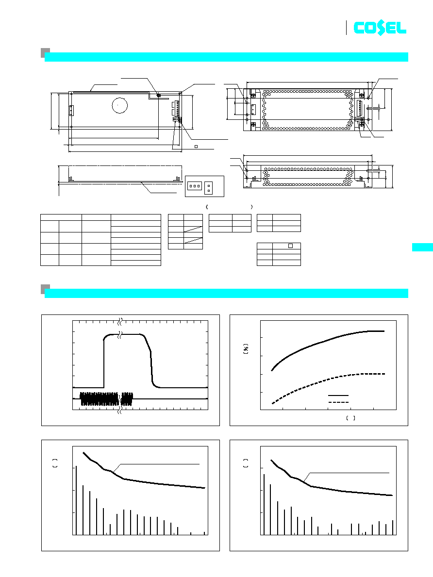
INPUT HARMONIC CURRENT (LEP100F-24)
�
EFFICIENCY (LEP100F-24)
�
INPUT HARMONIC CURRENT (LEP100F-24)
�
RISE TIME & FALL TIME (LEP100F-24)
DC Output
AC Input
Io=100%
20ms/DIV
100ms/DIV
ACIN 100V
86
78
80
82
84
76
100
60
140
180
220
260
300
100%
50%
Load factor
Load factor
EFFICIENCY
INPUT VOLTAGE
V
0
10
20
30
40
0.01
0.001
0.1
1
10
Load factor
Input voltage AC
Harmonic current standard class A
(at odd number)
100%
100V
HARMONIC ORDER
HARMONIC CURRENT
A
0
10
20
30
40
0.01
0.001
0.1
1
10
Load factor
Input voltage AC
Harmonic current standard class A
(at odd number)
100%
230V
HARMONIC ORDER
HARMONIC CURRENT
A
LEP
E-5
LEP100F
External view
I / O Connector Mating Connector
Terminal
(Mfr: J.S.T.)
CN1
CN2
CN3
CN4
B3P5-VH
B8P-VH
B2B-XH-A
B3B-XH-A
VHR-5N
VHR-8N
XHP-2
XHP-3
Chain : SVH-21T-P1.1
Loose: BVH-21T-P1.1
Chain : SVH-21T-P1.1
Loose: BVH-21T-P1.1
Chain : SXH-001T-P0.6
Loose: BXH-001T-P0.6
Chain : SXH-001T-P0.6
Loose: BXH-001T-P0.6
�
Keep drawing current per pin below 5A(7A at peak load)for CN2
�
Weight: 380g or less
�
Tolerance:
t
1
�
Dimensions in mm.
�
PCB Material : CEM3
�
Chassis and cover is optional.
�
Mounting torque: 1.5N
�
m(16kgf
�
cm)max
PIN CONNECTION
Pin No.
1
2
3
4
5
Input
AC(L)
AC(N)
FG
CN1
Pin No.
Output
CN2
(Option)
Pin No. Remote ON/OFF
CN3
RC(
+
)
RC(
-
)
1
, ,
2 3
,
4
,
6 7
,
8
5
,
1
2
(Option)
Pin No.
-Z
CN4
+
COM
-
1
2
3
-
V
+
V
(Without chassis and cover)
(Option)
(Option)
4.5
235+
-0.5
25
+
-
0.5
45
+
-
0.5
8
2-
�
4.5
CN3
CN4
�
4.5
2-M4
Mounting
Hole
Mounting
Hole
4-M4
8
235+
-0.5
252
RC(
-
)
RC(
+
)
+
COM
-
Name plate
Connector for Remote
ON/OFF (option)
Voltage adjust
Mounting
Hole
4-
�
3.5
+
-0.5
+
-
0.5
PCB t=1.6
CN4
CN3
(Lead)
3
max
Connector for
-Z (option)
CN2
CN1
Input(L)
Input(N)
FG
C119
(68)
CN2
4.5
42
85
46
15
20
CN1
30
20
CN3
CN4
(176)
212
222
75
65
5
5
32
-V
+V
5
1
1
3
5
8
4
Performance data

MODEL
LEP150F-24
LEP150F-36
LEP150F-48
DC OUTPUT
+24V 6.3(Peak 12)A
+36V 4.2(Peak 8)A
+48V 3.2(Peak 6)A
SPECIFICATIONS
MODEL
LEP150F-24
LEP150F-36
LEP150F-48
INPUT
VOLTAGE[V]
AC85 - 264 1
f
or DC 120 - 370
CURRENT[A]
ACIN 100V 2.0typ (Io=100%)
ACIN 200V 1.0typ (Io=100%)
FREQUENCY[Hz]
50/60 (47 - 63) or DC
EFFICIENCY[%]
ACIN 100V 82typ (Io=100%)
83typ (Io=100%)
84typ (Io=100%)
ACIN 200V 85typ (Io=100%)
86typ (Io=100%)
87typ (Io=100%)
POWER FACTOR
ACIN 100V 0.98typ (Io=100%)
ACIN 200V 0.93typ (Io=100%)
INRUSH CURRENT[A]
ACIN 100V 15typ (Io=100%) (At cold start) (Ta=25
C
)
ACIN 200V 30typ (Io=100%) (At cold start) (Ta=25
C
)
LEAKAGE CURRENT[mA]
0.75max (60Hz, According to IEC60950 and DEN-AN)
OUTPUT
VOLTAGE[V]
+24
+36
+48
CURRENT[A]
*
2
0 - 6.3 (Peak 12)
0 - 4.2 (Peak 8)
0 - 3.2 (Peak 6)
WATTAGE[W]
151.2 (Peak 288)
151.2 (Peak 288)
153.6 (Peak 288)
LINE REGULATION[mV]
48max
48max
48max
LOAD REGULATION[mV]
76max
90max
150max
RIPPLE[mVp-p]
0 to +45
C
*
3
120max
120max
150max
-10 - 0
C
*
3
160max
160max
300max
RIPPLE NOISE[mVp-p]
0 to +45
C
*
3
150max
150max
250max
-10 - 0
C
*
3
180max
180max
350max
TEMPERATURE REGULATION[mV]
0 to +45
C
120max
150max
240max
-10 to +45
C
145max
180max
300max
DRIFT[mV]
*
4
48max
48max
48max
START-UP TIME[ms]
500max (ACIN 100V, Io=100%)
HOLD-UP TIME[ms]
20typ (ACIN 100V, Io=100%)
OUTPUT VOLTAGE ADJUSTMENT RANGE[V]
21.4 - 26.4
26.4 - 39.6
39.6 - 52.8
OUTPUT VOLTAGE SETTING[V]
23.0 - 25.0
35.0 - 37.0
46.0 - 50.0
PROTECTION
CIRCUIT AND
OTHERS
OVERCURRENT PROTECTION
Works over 101% of peak current and recovers automatically
OVERVOLTAGE PROTECTION
Works at 115 - 140% of rating
REMOTE ON/OFF
Option (Refer to Instruction Manual)
ISOLATION
INPUT-OUTPUT
-
RC
*
5
AC3,000V 1minute, Cutoff current = 10mA, DC500V 50M
W
min (At Room Temperature)
INPUT-FG
AC2,000V 1minute, Cutoff current = 10mA, DC500V 50M
W
min (At Room Temperature)
OUTPUT
-
RC-FG
*
5
AC500V 1minute, Cutoff current = 100mA, DC500V 50M
W
min (At Room Temperature)
OUTPUT-RC
*
5
AC100V 1minute, Cutoff current = 100mA, DC100V 10M
W
min (At Room Temperature)
ENVIRONMENT
OPERATING TEMP.,HUMID.AND ALTITUDE
-10 to +70
C
, 20 - 90%RH (Non condensing) (Refer to DERATING CURVE), 3,000m (10,000feet) max
STORAGE TEMP.,HUMID.AND ALTITUDE
-20 to +75
C
, 20 - 90%RH (Non condensing), 9,000m (30,000feet) max
VIBRATION
10 - 55Hz, 19.6m/s
2
(2G), 3minutes period, 60minutes each along X, Y and Z axis
IMPACT
196.1m/s
2
(20G), 11ms, once each X, Y and Z axis
SAFETY AND
NOISE
REGULATIONS
AGENCY APPROVALS
UL60950-1, C-UL(CSA60950-1), EN60950-1, EN50178 Complies with DEN-AN and IEC60950-1 (At only AC input)
CE MARKING
Low Voltage Directive, EMC Directive
CONDUCTED NOISE
Complies with FCC-B, CISPR22-B, EN55022-B, VCCI-B
HARMONIC ATTENUATOR
Complies with IEC61000-3-2
OTHERS
CASE SIZE/WEIGHT
85
X
40
X
222mm (W
X
H
X
D) /490g max (without chassis and cover)
COOLING METHOD
Convection
*
1
Specification is changed at option, refer to Instruction Manual 6.
*
2
Peak loading for 10sec. And Duty 35% max, refer to Instruction Manual 5. In detail.
*
3
This is the value that measured on measuring board with capacitor of 22
m
F within 150mm
from output terminal.Measured by 20MHz oscilloscope or Ripple-Noise meter (Equivalent to
KEISOKU-GIKEN: RM101).
*
4
Drift is the change in DC output for an eight hour period after a half-hour warm-up at 25
C
,
with the input voltage held constant at the rated input/output.
*
5
Applicable when remote control (optional) is added.
*
Parallel operation with other model is not possible.
*
Derating is required when operated with chassis and cover.
*
A sound may occur from power supply at peak loading.
LEP150F
Rugged PCB type
LEP 150
F
-24
-
O
Ordering information
1
Series name
2
Output wattage
3
Universal input
4
Output voltage
5
Optional
*
1
G :Low leakage current
R :with Remote ON/OFF
S :with Chassis
SN:with Chassis & cover
T :Vertical terminal block
U :Operating stop voltage
is set at a lower value
Z :with ZT
R
1
2
3
4
5
LEP
E-6
Recommended Noise Filter
NAC-06-472
High voltage pulse noise type : NAP series
Low leakage current type : NAM series
*The Noise Filter is recommended
*
to connect with several devices.

�
INPUT HARMONIC CURRENT (LEP150F-24)
�
EFFICIENCY (LEP150F-24)
�
INPUT HARMONIC CURRENT (LEP150F-24)
�
RISE TIME & FALL TIME (LEP150F-24)
DC Output
AC Input
Io=100%
20ms/DIV
100ms/DIV
ACIN 100V
100
60
140
180
220
260
300
100%
50%
Load factor
Load factor
EFFICIENCY
INPUT VOLTAGE
V
0
10
20
30
40
0.01
0.001
0.1
1
10
Load factor
Input voltage AC
Harmonic current standard class A
(at odd number)
100%
100V
HARMONIC ORDER
HARMONIC CURRENT
A
0
10
20
30
40
0.01
0.001
0.1
1
10
Load factor
Input voltage AC
Harmonic current standard class A
(at odd number)
100%
230V
HARMONIC ORDER
HARMONIC CURRENT
A
88
82
80
78
86
84
76
LEP
E-7
LEP150F
External view
I / O Connector Mating Connector
Terminal
(Mfr: J.S.T.)
CN1
CN2
CN3
CN4
B3P5-VH
B8P-VH
B2B-XH-A
B3B-XH-A
VHR-5N
VHR-8N
XHP-2
XHP-3
Chain : SVH-21T-P1.1
Loose: BVH-21T-P1.1
Chain : SVH-21T-P1.1
Loose: BVH-21T-P1.1
Chain : SXH-001T-P0.6
Loose: BXH-001T-P0.6
Chain : SXH-001T-P0.6
Loose: BXH-001T-P0.6
�
Keep drawing current per pin below 5A(7A at peak load)for CN2
�
Weight: 490g or less
�
Tolerance:
t
1
�
Dimensions in mm.
�
PCB Material : CEM3
�
Chassis and cover is optional.
�
Mounting torque: 1.5N
�
m(16kgf
�
cm)max
PIN CONNECTION
Pin No.
1
2
3
4
5
Input
AC(L)
AC(N)
FG
CN1
(Option)
Pin No. Remote ON/OFF
CN3
RC(
+
)
RC(
-
)
1
2
(Option)
Pin No.
-Z
CN4
+
COM
-
1
2
3
(Without chassis and cover)
(Option)
(Option)
235+
-0.5
35
30
20
+
+
-
0.5
55
-
0.5
CN1
2-
�
4.5
235+
-0.5
�
4.5
2-M4
Mounting
Hole
Mounting
Hole
4-M4
Name plate
Voltage adjust
5
Mounting
Hole
5-
�
3.5
105+
-0.5
212
222
+
-0.5
+
-
0.5
PCB t=1.6
(Lead)
3
ma
x
RC(
-
)
RC(
+
)
+
COM
-
CN4
CN3
Connector for Remote
ON/OFF (option)
Connector for
-Z (option)
Pin No.
Output
CN2
1
, ,
2 3
,
4
,
6 7
,
8
5
,
-
V
+
V
CN4
4.5
8
95
CN2
4.5
CN4
CN3
15
51
25
8
252
CN3
(68)
(215)
5
75
85
37
47
-V
+V
Input(L)
Input(N)
FG
5
CN1
1
5
1
CN2
8
4
C119
3
Performance data

MODEL
LEP240F-24
LEP240F-36
LEP240F-48
DC OUTPUT
+24V 10(Peak 20)A
+36V 6.7(Peak 13.4)A
+48V 5(Peak 10)A
SPECIFICATIONS
MODEL
LEP240F-24
LEP240F-36
LEP240F-48
INPUT
VOLTAGE[V]
AC85 - 264 1
f
or DC 120 - 370
CURRENT[A]
ACIN 100V 3.3typ (Io=100%)
ACIN 200V 1.7typ (Io=100%)
FREQUENCY[Hz]
50/60 (47 - 63) or DC
EFFICIENCY[%]
ACIN 100V 83typ (Io=100%)
84typ (Io=100%)
84typ (Io=100%)
ACIN 200V 86typ (Io=100%)
87typ (Io=100%)
87typ (Io=100%)
POWER FACTOR
ACIN 100V 0.98typ (Io=100%)
ACIN 200V 0.93typ (Io=100%)
INRUSH CURRENT[A]
ACIN 100V 15typ (Io=100%) (More than 3sec.to re-start)
ACIN 200V 30typ (Io=100%) (More than 3sec.to re-start)
LEAKAGE CURRENT[mA]
0.75max (60Hz, According to IEC60950 and DEN-AN)
OUTPUT
VOLTAGE[V]
+24
+36
+48
CURRENT[A]
*
2
0 - 10 (Peak 20)
0 - 6.7 (Peak 13.4)
0 - 5 (Peak 10)
WATTAGE[W]
240.0 (Peak 480)
241.2 (Peak 482.4)
240.0 (Peak 480)
LINE REGULATION[mV]
48max
48max
48max
LOAD REGULATION[mV]
76max
90max
150max
RIPPLE[mVp-p]
0 to +40
C
*
3
120max
120max
150max
-10 - 0
C
*
3
160max
160max
300max
RIPPLE NOISE[mVp-p]
0 to +40
C
*
3
150max
150max
250max
-10 - 0
C
*
3
180max
180max
350max
TEMPERATURE REGULATION[mV]
0 to +40
C
120max
150max
240max
-10 to +40
C
145max
180max
300max
DRIFT[mV]
*
4
48max
48max
48max
START-UP TIME[ms]
500max (ACIN 100V, Io=100%)
HOLD-UP TIME[ms]
20typ (ACIN 100V, Io=100%)
OUTPUT VOLTAGE ADJUSTMENT RANGE[V]
21.4 - 26.4
26.4 - 39.6
39.6 - 52.8
OUTPUT VOLTAGE SETTING[V]
23.0 - 25.0
35.0 - 37.0
46.0 - 50.0
PROTECTION
CIRCUIT AND
OTHERS
OVERCURRENT PROTECTION
Works over 101% of peak current and recovers automatically
OVERVOLTAGE PROTECTION
Works at 115 - 140% of rating
REMOTE ON/OFF
Option (Refer to Instruction Manual)
ISOLATION
INPUT-OUTPUT
-
RC
*
5
AC3,000V 1minute, Cutoff current = 10mA, DC500V 50M
W
min (At Room Temperature)
INPUT-FG
AC2,000V 1minute, Cutoff current = 10mA, DC500V 50M
W
min (At Room Temperature)
OUTPUT
-
RC-FG
*
5
AC500V 1minute, Cutoff current = 100mA, DC500V 50M
W
min (At Room Temperature)
OUTPUT-RC
*
5
AC100V 1minute, Cutoff current = 100mA, DC100V 10M
W
min (At Room Temperature)
ENVIRONMENT
OPERATING TEMP.,HUMID.AND ALTITUDE
-10 to +70
C
, 20 - 90%RH (Non condensing) (Refer to DERATING CURVE), 3,000m (10,000feet) max
STORAGE TEMP.,HUMID.AND ALTITUDE
-20 to +75
C
, 20 - 90%RH (Non condensing), 9,000m (30,000feet) max
VIBRATION
10 - 55Hz, 19.6m/s
2
(2G), 3minutes period, 60minutes each along X, Y and Z axis
IMPACT
196.1m/s
2
(20G), 11ms, once each X, Y and Z axis
SAFETY AND
NOISE
REGULATIONS
AGENCY APPROVALS
UL60950-1, C-UL(CSA60950-1), EN60950-1, EN50178 Complies with DEN-AN and IEC60950-1 (At only AC input)
CE MARKING
Low Voltage Directive, EMC Directive
CONDUCTED NOISE
Complies with FCC-B, CISPR22-B, EN55022-B, VCCI-B
HARMONIC ATTENUATOR
Complies with IEC61000-3-2
OTHERS
CASE SIZE/WEIGHT
95
X
45
X
222mm (W
X
H
X
D) /690g max (without chassis and cover)
COOLING METHOD
Convection
*
1
Specification is changed at option, refer to Instruction Manual 6.
*
2
Peak loading for 10sec. And Duty 35% max, refer to Instruction Manual 5. In detail.
*
3
This is the value that measured on measuring board with capacitor of 22
m
F within 150mm
from output terminal.Measured by 20MHz oscilloscope or Ripple-Noise meter (Equivalent to
KEISOKU-GIKEN: RM101).
*
4
Drift is the change in DC output for an eight hour period after a half-hour warm-up at 25
C
,
with the input voltage held constant at the rated input/output.
*
5
Applicable when remote control (optional) is added.
*
Parallel operation with other model is not possible.
*
Derating is required when operated with chassis and cover.
*
A sound may occur from power supply at peak loading.
LEP240F
Rugged PCB type
LEP 240
F
-24
-
O
Ordering information
1
Series name
2
Output wattage
3
Universal input
4
Output voltage
5
Optional
*
1
G :Low leakage current
R :with Remote ON/OFF
S :with Chassis
SN:with Chassis & cover
T :Vertical terminal block
U :Operating stop voltage
is set at a lower value
Z :with ZT
R
1
2
3
4
5
LEP
E-8
Recommended Noise Filter
NAC-06-472
High voltage pulse noise type : NAP series
Low leakage current type : NAM series
*The Noise Filter is recommended
*
to connect with several devices.

�
INPUT HARMONIC CURRENT (LEP240F-24)
�
EFFICIENCY (LEP240F-24)
�
INPUT HARMONIC CURRENT (LEP240F-24)
�
RISE TIME & FALL TIME (LEP240F-24)
DC Output
AC Input
Io=100%
20ms/DIV
100ms/DIV
ACIN 100V
80
82
84
86
88
78
110
160
210
260
60
310
100%
50%
Load factor
Load factor
EFFICIENCY
INPUT VOLTAGE
V
0
10
20
30
40
0.01
0.001
0.1
1
10
Load factor
Input voltage AC
Harmonic current standard class A
(at odd number)
100%
100V
HARMONIC ORDER
HARMONIC CURRENT
A
0
10
20
30
40
0.01
0.001
0.1
1
10
Load factor
Input voltage AC
Harmonic current standard class A
(at odd number)
100%
230V
HARMONIC ORDER
HARMONIC CURRENT
A
LEP
E-9
LEP240F
External view
I / O Connector Mating Connector
Terminal
(Mfr: J.S.T.)
CN1
CN2
CN3
CN4
B3P5-VH
B8P-VH
B2B-XH-A
B3B-XH-A
VHR-5N
VHR-8N
XHP-2
XHP-3
Chain : SVH-21T-P1.1
Loose: BVH-21T-P1.1
Chain : SVH-21T-P1.1
Loose: BVH-21T-P1.1
Chain : SXH-001T-P0.6
Loose: BXH-001T-P0.6
Chain : SXH-001T-P0.6
Loose: BXH-001T-P0.6
�
Keep drawing current per pin below 5A(7A at peak load)for CN2
�
Weight: 690g or less
�
Tolerance:
t
1
�
Dimensions in mm.
�
PCB Material : CEM3
�
Chassis and cover is optional.
�
Mounting torque: 1.5N
�
m(16kgf
�
cm)max
PIN CONNECTION
Pin No.
1
2
3
4
5
Input
AC(L)
AC(N)
FG
CN1
(Option)
Pin No. Remote ON/OFF
CN3
RC(
+
)
RC(
-
)
RC(
-
)
RC(
+
)
1
2
(Option)
Pin No.
-Z
CN4
+
COM
-
+
COM
-
1
2
3
(Without chassis and cover)
(Option)
(Option)
CN4
CN3
Mounting
Hole
5-
�
3.5
Name plate
Connector for Remote
ON/OFF (option)
5
124 +
-0.5
222
212 +
-0.5
PCB t=1.6
5
95
85
+
-
0.5
45
+
-
0.5
65
+
-
0.5
(Lead)
3
ma
x
Connector for
-Z (option)
2-
�
4.5
�
4.5
2-M4
Mounting
Hole
Mounting
Hole
4-M4
235+
-0.5
235+
-0.5
252
Pin No.
Output
CN2
1
, ,
2 3
,
4
,
6 7
,
8
5
,
-
V
+
V
Voltage adjust
(66)
CN4
4.5
52
8
CN2
33
23
4.5
CN4
CN3
15
30
58
8
CN3
(213)
42
108
CN1
Input(L)
Input(N)
FG
-V
+V
3
C119
CN2
5
1
5
1
8
4
CN1
Performance data