MODEL
PBW15F-12
PBW15F-15
MAX OUTPUT WATTAGE[W]
*
5
16.8
15.0
DC OUTPUT
VOLTAGE[V]
*
6
t
12 ( +24 )
t
15 ( +30 )
CURRENT1[A] 0.7
0.5
CURRENT2[A]
*
5
1.4
1.0
SPECIFICATIONS
MODEL
PBW15F-12
PBW15F-15
INPUT
VOLTAGE[V]
AC85 - 264 1
f
or DC110 - 370 (AC50 or DC70 Please refer to the instruction manual 2.1 Input voltage
*
8)
CURRENT[A]
ACIN 100V 0.40typ (CURRENT1)
ACIN 200V 0.20typ (CURRENT1)
FREQUENCY[Hz]
50/60 (47 - 440) or DC
EFFICIENCY[%]
ACIN 100V 74typ (CURRENT1)
78typ (CURRENT1)
ACIN 200V 77typ (CURRENT1)
80typ (CURRENT1)
INRUSH CURRENT[A]
ACIN 100V 15typ (CURRENT1) (At cold start)
ACIN 200V 30typ (CURRENT1) (At cold start)
LEAKAGE CURRENT[mA]
0.15/0.30max (ACIN 100V/240V 60Hz, Io=100%, According to IEC60950-1,DENAN)
OUTPUT
VOLTAGE[V]
t
12
/ ( +24V reference number )
t
15
/ ( +30V reference number )
CURRENT1[A]
0.7
/ 0.7
0.5
/ 0.5
CURRENT2[A]
*
5
1.4
/ -
1.0
/ -
LINE REGULATION[mV]
*
9
60max
/ 96max
60max
/ 96max
LOAD REGULATION 1[mV]
*
3
600max
/ 150max
600max
/ 150max
LOAD REGULATION 2[mV]
*
4
750max
/ -
750max
/ -
RIPPLE[mVp-p]
0 to +50
C
*
1
120max
/ 240max
120max
/ 240max
-10 - 0
C
*
1
160max
/ 320max
160max
/ 320max
RIPPLE NOISE[mVp-p]
0 to +50
C
*
1
150max
/ 300max
150max
/ 300max
-10 - 0
C
*
1
180max
/ 360max
180max
/ 360max
TEMPERATURE REGULATION[mV]
0 to +50
C
120max
150max
-10 to +50
C
150max
180max
DRIFT[mV]
*
2
48max
60max
START-UP TIME[ms]
200typ(ACIN 100V, Io=100%)
*
Start-up time is 700ms typ for less than 1minute of applying input again from turning off the input voltage.
HOLD-UP TIME[ms]
20typ (ACIN 100V, Io=100%)
OUTPUT VOLTAGE ADJUSTMENT RANGE[V]
9.60 - 13.2 (+V and -V are simultaneously adjusted)
13.2 - 16.5 (+V and -V are simultaneously adjusted)
OUTPUT VOLTAGE SETTING[V]
11.5 - 12.5 (+V and -V CURRENT1)
14.4 - 15.6 (+V and -V CURRENT1)
PROTECTION
CIRCUIT AND
OTHERS
OVERCURRENT PROTECTION
Works over 105% of rated current and recovers automatically
OVERVOLTAGE PROTECTION[V]
16.8 - 24.0
20.0 - 29.0
OPERATING INDICATION
LED (Green)
REMOTE ON/OFF
None
ISOLATION
INPUT-OUTPUT
AC3,000V 1minute, Cutoff current = 10mA, DC500V 50M
W
min (At Room Temperature)
INPUT-FG
AC2,000V 1minute, Cutoff current = 10mA, DC500V 50M
W
min (At Room Temperature)
OUTPUT-FG
AC500V 1minute, Cutoff current = 25mA, DC500V 50M
W
min (At Room Temperature)
ENVIRONMENT
OPERATING TEMP.,HUMID.AND ALTITUDE
-10 to +71
C
(Required Derating), 20 - 90%RH (Non condensing) 3,000m (10,000feet) max
STORAGE TEMP.,HUMID.AND ALTITUDE
-20 to +75
C
, 20 - 90%RH (Non condensing) 3,000m (10,000feet) max
VIBRATION
10 - 55Hz, 19.6m/s
2
(2G), 3minutes period, 60minutes each along X, Y and Z axis
IMPACT
196.1m/s
2
(20G), 11ms, once each X, Y and Z axis
SAFETY AND
NOISE
REGULATIONS
AGENCY APPROVALS (At only AC input)
UL60950-1, C-UL(CSA60950-1), EN60950-1, EN50178 Complies with DEN-AN
CONDUCTED NOISE
Complies with FCC Part15 classB, VCCI-B, CISPR22-B, EN55011-B, EN55022-B
CE MARKING
Low Voltage Directive, EMC Directive
HARMONIC ATTENUATOR
Complies with IEC61000-3-2 (Not built-in to active filter
*
7)
OTHERS
CASE SIZE/WEIGHT
31
X
78
X
85mm (without terminal block) (W
X
H
X
D) / 200g max (without cover)
COOLING METHOD
Convection
*
1
Measured by 20MHz oscilloscope or Ripple-Noise
meter(equivalent to KEISOKU-GIKEN : RM101).
*
2
Drift is the change in DC output for an eight hour period
after a half-hour warm-up at 25
C
.
*
3
Figures for 0 to rated current 1.The current not measured
side is fixed.
*
4
Figures for 0 to rated current 2.The current not measured
side is fixed.
*
5
The sum of +power -power must be less than output power.
*
6
t
12,
t
15 can be used as +24 and +30.
*
7 When two or more units are used,they may not comply with
the harmonic attenuator. Please contact us for details.
*
8 Derating is required.
*
9
Figures to rated current 1.
*
Parallel operation with other model is not possible.
*
Derating is required when operated with cover.
*
A sound may occur from power supply at peak loading.
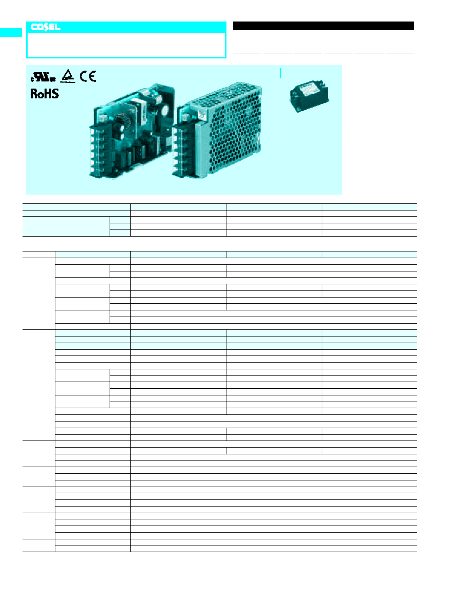
PBW15F
Unit type
PB
W
15
F
-
O
-
O
Ordering information
1
Series name
2
Dual output
3
Output wattage
4
Universal input
5
Output voltage
6
Optional
C :with Coating
G :Low leakage current
E :Low leakage current
and EMI class A
T :Vertical terminal block
J :Connector type
N :with Cover
N1 :with DIN rail
V :Output voltage setting
potentiometer external-
ly
R
1
2
3
4
5
6
PB
A-26
Recommended Noise Filter
NAC-06-472
High voltage pulse noise type : NAP series
Low leakage current type : NAM series
*The Noise Filter is recommended
*
to connect with several devices.
Cover is optional
2.5
Point A:C102
Mounting hole
2-M3
Mounting hole
2-M3
-V
AC(N)
AC(L)
FG
COM
+V
Cover name plate
Cover (option)
Name plate
M3
Terminal cover
5
18
31
34.5
34.5
78
36.5
85
70.5
12.2
�
1.5
18
31
�
0.5
60
�
0.5
11.5
9.5
7.5
16.5
�
2
15.1
�
1.5
22.6
�
1.5
PBA15F
PBW15F
LED
Voltage adjust
�
Tolerance :
�
1
�
Mass : 200g or less (without cover)
�
PCB Material/thickness : CEM3 / 1.6mm
�
Chassis material : Electric galvanizing steel board
�
Dimensions in mm
�
Mounting torque : 0.6N
�
m(6.3kgf
�
cm)max
�
Screw tightening torque : M3 0.8N
�
m(8.5kgf
�
cm)max
�
Please connect safety ground to the unit in 2-M3 holes.
�
External size of option T,J,N,N1 and V is different from standard model and refer to 7 Option of instruction manual for details.
PB
A-27
PBW15F
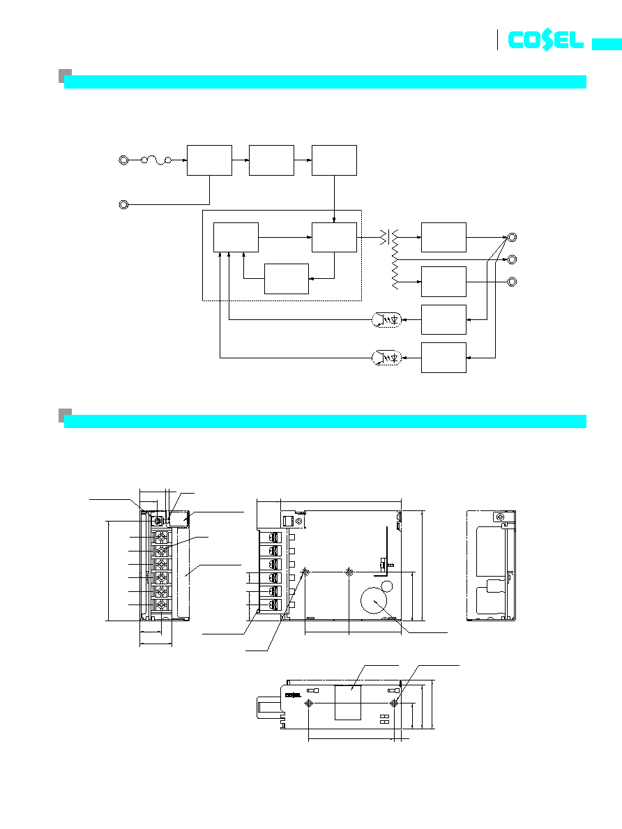
Block diagram
2.5A
AC250V
AC IN
+
V
COM
DC
OUT
-
V
FG
85
- 264V
NOISE
FILTER
INVERTER
CONTROL
CURRENT
SENSING
RECTIFIER
AND
FILTER
RECTIFIER
AND
FILTER
CONTROL
Photocoupler
Photocoupler
TRANSFORMER
INRUSH
CURRENT
LIMIT
FUSE
OVER VOLTAGE
PROTECTION
RECTIFIER
AND
FILTER
External view
MODEL
PBW30F-5
PBW30F-12
PBW30F-15
MAX OUTPUT WATTAGE[W]
*
5
15
31.2
30.0
DC OUTPUT
VOLTAGE[V]
*
6
t
5 ( +10 )
t
12 ( +24 )
t
15 ( +30 )
CURRENT1[A] 1.5
1.3
1.0
CURRENT2[A]
*
5
2.0
1.7
1.4
SPECIFICATIONS
MODEL
PBW30F-5
PBW30F-12
PBW30F-15
INPUT
VOLTAGE[V]
AC85 - 264 1
f
or DC110 - 370 (AC50 or DC70 Please refer to the instruction manual 2.1 Input voltage
*
8)
CURRENT[A]
ACIN 100V 0.4typ (CURRENT1)
0.7typ (CURRENT1)
ACIN 200V 0.25typ (CURRENT1)
0.4typ (CURRENT1)
FREQUENCY[Hz]
50/60 (47 - 440) or DC
EFFICIENCY[%]
ACIN 100V 75typ (CURRENT1)
77typ (CURRENT1)
78typ (CURRENT1)
ACIN 200V 75typ (CURRENT1)
81typ (CURRENT1)
79typ (CURRENT1)
INRUSH CURRENT[A]
ACIN 100V 15typ (CURRENT1) (At cold start)
ACIN 200V 30typ (CURRENT1) (At cold start)
LEAKAGE CURRENT[mA]
0.30/0.65max (ACIN 100V/240V 60Hz, Io=100%, According to IEC60950-1,DENAN)
OUTPUT
VOLTAGE[V]
t
5
/ ( +10V reference number )
t
12
/ ( +24V reference number )
t
15
/ ( +30V reference number )
CURRENT1[A]
1.5
/ 1.5
1.3
/ 1.3
1.0
/ 1.0
CURRENT2[A]
*
5
2.0
/ -
1.7
/ -
1.4
/ -
LINE REGULATION[mV]
*
9
20max
/ 36max
60max
/ 96max
60max
/ 96max
LOAD REGULATION 1[mV]
*
3
250max
/ 100max
600max
/ 150max
600max
/ 150max
LOAD REGULATION 2[mV]
*
4
500max
/ -
750max
/ -
750max
/ -
RIPPLE[mVp-p]
0 to +50
C
*
1
80max
/ 240max
120max
/ 240max
120max
/ 240max
-10 - 0
C
*
1
140max
/ 320max
160max
/ 320max
160max
/ 320max
RIPPLE NOISE[mVp-p]
0 to +50
C
*
1
120max
/ 300max
150max
/ 300max
150max
/ 300max
-10 - 0
C
*
1
160max
/ 360max
180max
/ 360max
180max
/ 360max
TEMPERATURE REGULATION[mV]
0 to +50
C
50max
120max
150max
-10 to +50
C
60max
150max
180max
DRIFT[mV]
*
2
20max
48max
60max
START-UP TIME[ms]
200typ(ACIN 100V, Io=100%)
*
Start-up time is 700ms typ for less than 1minute of applying input again from turning off the input voltage.
HOLD-UP TIME[ms]
20typ (ACIN 100V, Io=100%)
OUTPUT VOLTAGE ADJUSTMENT RANGE[V]
4.99 - 6.00 (+V and -V are simultaneously adjusted) 9.60 - 13.2 (+V and -V are simultaneously adjusted) 13.2 - 16.5 (+V and -V are simultaneously adjusted)
OUTPUT VOLTAGE SETTING[V]
4.99 - 5.30 (+V and -V CURRENT1)
11.5 - 12.5 (+V and -V CURRENT1)
14.4 - 15.6 (+V and -V CURRENT1)
PROTECTION
CIRCUIT AND
OTHERS
OVERCURRENT PROTECTION
Works over 105% of rated current and recovers automatically
OVERVOLTAGE PROTECTION[V]
6.90 - 10.0
16.8 - 24.0
20.0 - 29.0
OPERATING INDICATION
LED (Green)
REMOTE ON/OFF
None
ISOLATION
INPUT-OUTPUT
AC3,000V 1minute, Cutoff current = 10mA, DC500V 50M
W
min (At Room Temperature)
INPUT-FG
AC2,000V 1minute, Cutoff current = 10mA, DC500V 50M
W
min (At Room Temperature)
OUTPUT-FG
AC500V 1minute, Cutoff current = 25mA, DC500V 50M
W
min (At Room Temperature)
ENVIRONMENT
OPERATING TEMP.,HUMID.AND ALTITUDE
-10 to +71
C
(Required Derating), 20 - 90%RH (Non condensing) 3,000m (10,000feet) max
STORAGE TEMP.,HUMID.AND ALTITUDE
-20 to +75
C
, 20 - 90%RH (Non condensing) 3,000m (10,000feet) max
VIBRATION
10 - 55Hz, 19.6m/s
2
(2G), 3minutes period, 60minutes each along X, Y and Z axis
IMPACT
196.1m/s
2
(20G), 11ms, once each X, Y and Z axis
SAFETY AND
NOISE
REGULATIONS
AGENCY APPROVALS (At only AC input)
UL60950-1, C-UL(CSA60950-1), EN60950-1, EN50178 Complies with DEN-AN
CONDUCTED NOISE
Complies with FCC Part15 classB, VCCI-B, CISPR22-B, EN55011-B, EN55022-B
CE MARKING
Low Voltage Directive, EMC Directive
HARMONIC ATTENUATOR
Complies with IEC61000-3-2 (Not built-in to active filter
*
7)
OTHERS
CASE SIZE/WEIGHT
31
X
78
X
103mm (without terminal block) (W
X
H
X
D) / 270g max (without cover)
COOLING METHOD
Convection
*
1
Measured by 20MHz oscilloscope or Ripple-Noise
meter(equivalent to KEISOKU-GIKEN : RM101).
*
2
Drift is the change in DC output for an eight hour period
after a half-hour warm-up at 25
C
.
*
3
Figures for 0 to rated current 1.The current not measured
side is fixed.
*
4
Figures for 0 to rated current 2.The current not measured
side is fixed.
*
5
The sum of +power -power must be less than output power.
*
6
t
5,
t
12,
t
15 can be used as +10,+24 and +30.
*
7 When two or more units are used,they may not comply with
the harmonic attenuator. Please contact us for details.
*
8 Derating is required.
*
9
Figures to rated current 1.
*
Parallel operation with other model is not possible.
*
Derating is required when operated with cover.
*
A sound may occur from power supply at peak loading.
PBW30F
Unit type
PB
W
30
F
-
O
-
O
Ordering information
1
Series name
2
Dual output
3
Output wattage
4
Universal input
5
Output voltage
6
Optional
C :with Coating
G :Low leakage current
E :Low leakage current
and EMI class A
T :Vertical terminal block
J :Connector type
N :with Cover
N1 :with DIN rail
V :Output voltage setting
potentiometer external-
ly
R
1
2
3
4
5
6
PB
A-28
Recommended Noise Filter
NAC-06-472
High voltage pulse noise type : NAP series
Low leakage current type : NAM series
*The Noise Filter is recommended
*
to connect with several devices.
Cover is optional
2.5
Mounting hole
2-M3
Mounting hole
2-M3
Point A:C102
Name plate
Cover name plate
Cover (option)
M3
Terminal cover
-V
AC(N)
AC(L)
FG
COM
+V
18
12.2
�
1.5
70.5
18
36.5
46
�
0.5
40.5
75
�
0.5
8.5
15.1
�
1.5
22.6
�
1.5
11.5
9.5
7.5
16.5
�
2
31
103
78
34.5
PBW30F
PBA30F
�
Tolerance :
�
1
�
Mass : 270g or less (without cover)
�
PCB Material/thickness : CEM3 / 1.6mm
�
Chassis material : Electric galvanizing steel board
�
Dimensions in mm
�
Mounting torque : 0.6N
�
m(6.3kgf
�
cm)max
�
Screw tightening torque : M3 0.8N
�
m(8.5kgf
�
cm)max
�
Please connect safety ground to the unit in 2-M3 holes.
�
External size of option T,J,N,N1 and V is different from standard model and refer to 7 Option of instruction manual for details.
LED
Voltage adjust
PB
A-29
PBW30F
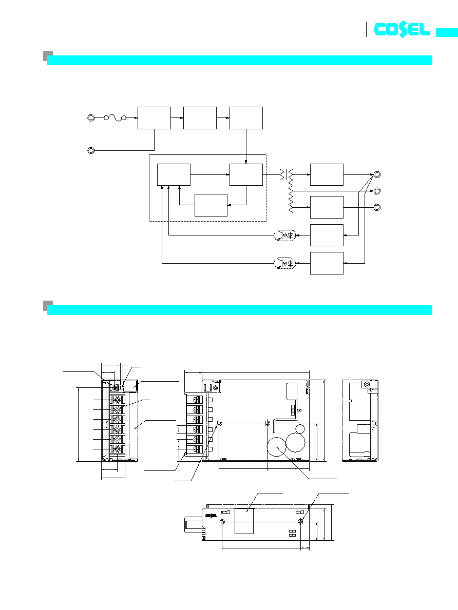
Block diagram
3.15A
AC250V
NOISE
FILTER
AC IN
+
V
COM
DC
OUT
-
V
FG
85
- 264V
NOISE
FILTER
INVERTER
CONTROL
CURRENT
SENSING
RECTIFIER
AND
FILTER
RECTIFIER
AND
FILTER
CONTROL
Photocoupler
Photocoupler
TRANSFORMER
INRUSH
CURRENT
LIMIT
FUSE
OVER VOLTAGE
PROTECTION
RECTIFIER
AND
FILTER
External view
MODEL
PBW50F-5
PBW50F-12
PBW50F-15
MAX OUTPUT WATTAGE[W]
*
6
30
50.4
51
DC OUTPUT
VOLTAGE[V]
*
8
t
5 ( +10 )
t
12 ( +24 )
t
15 ( +30 )
CURRENT1[A] 3.0
2.1
1.7
CURRENT2[A]
*
6
4.0
2.7
2.4
SPECIFICATIONS
MODEL
PBW50F-5
PBW50F-12
PBW50F-15
INPUT
VOLTAGE[V]
AC85 - 264 1
f
or DC120 - 370 (AC50 or DC70 Please refer to the instruction manual 2.1 Input voltage
*
3)
CURRENT[A]
ACIN 100V 0.45typ (CURRENT1)
0.70typ (CURRENT1)
ACIN 200V 0.30typ (CURRENT1)
0.40typ (CURRENT1)
FREQUENCY[Hz]
50/60 (47 - 63)
EFFICIENCY[%]
ACIN 100V 76typ (CURRENT1)
81typ (CURRENT1)
81typ (CURRENT1)
ACIN 200V 77typ (CURRENT1)
83typ (CURRENT1)
83typ (CURRENT1)
POWER FACTOR(Io=100%)
ACIN 100V 0.98typ
0.99typ
ACIN 200V 0.87typ
0.93typ
INRUSH CURRENT[A]
ACIN 100V 15typ (CURRENT1) (At cold start)
ACIN 200V 30typ (CURRENT1) (At cold start)
LEAKAGE CURRENT[mA]
0.40/0.75max (ACIN 100V/240V 60Hz, Io=100%, According to IEC60950-1,DENAN)
OUTPUT
VOLTAGE[V]
t
5
/ ( +10V reference number )
t
12
/ ( +24V reference number )
t
15
/ ( +30V reference number )
CURRENT1[A]
3.0
/ 3.0
2.1
/ 2.1
1.7
/ 1.7
CURRENT2[A]
*
6
4.0
/ -
2.7
/ -
2.4
/ -
LINE REGULATION[mV]
20max
/ 36max
48max
/ 96max
60max
/ 96max
LOAD REGULATION 1[mV]
*
4
250max
/ 100max
600max
/ 150max
600max
/ 150max
LOAD REGULATION 2[mV]
*
5
500max
/ -
750max
/ -
750max
/ -
RIPPLE[mVp-p]
0 to +50
C
*
1
80max
/ 240max
120max
/ 240max
120max
/ 240max
-10 - 0
C
*
1
140max
/ 320max
160max
/ 320max
160max
/ 320max
RIPPLE NOISE[mVp-p]
0 to +50
C
*
1
120max
/ 300max
150max
/ 300max
150max
/ 300max
-10 - 0
C
*
1
160max
/ 360max
180max
/ 360max
180max
/ 360max
TEMPERATURE REGULATION[mV]
0 to +50
C
50max
120max
150max
-10 to +50
C
60max
150max
180max
DRIFT[mV]
*
2
20max
48max
60max
START-UP TIME[ms]
350typ(ACIN 100V, Io=100%)
HOLD-UP TIME[ms]
20typ (ACIN 100V, Io=100%)
OUTPUT VOLTAGE ADJUSTMENT RANGE[V]
4.99 - 6.00 (+V and -V are simultaneously adjusted) 9.60 - 13.2 (+V and -V are simultaneously adjusted) 13.2 - 16.5 (+V and -V are simultaneously adjusted)
OUTPUT VOLTAGE SETTING[V]
4.99 - 5.30 (+V and -V CURRENT1)
11.5 - 12.5 (+V and -V CURRENT1)
14.4 - 15.6 (+V and -V CURRENT1)
PROTECTION
CIRCUIT AND
OTHERS
OVERCURRENT PROTECTION
Works over 105% of rated current and recovers automatically
OVERVOLTAGE PROTECTION[V]
6.90 - 10.0
16.8 - 24.0
20.0 - 29.0
OPERATING INDICATION
LED (Green)
REMOTE ON/OFF
Optional (Required external power source)
ISOLATION
INPUT-OUTPUT
-
RC
*
7
AC3,000V 1minute, Cutoff current = 10mA, DC500V 50M
W
min (At Room Temperature)
INPUT-FG
AC2,000V 1minute, Cutoff current = 10mA, DC500V 50M
W
min (At Room Temperature)
OUTPUT
-
RC-FG
*
7
AC500V 1minute, Cutoff current = 100mA, DC500V 50M
W
min (At Room Temperature)
ENVIRONMENT
OPERATING TEMP.,HUMID.AND ALTITUDE
-10 to +71
C
(Required Derating), 20 - 90%RH (Non condensing) 3,000m (10,000feet) max
STORAGE TEMP.,HUMID.AND ALTITUDE
-20 to +75
C
, 20 - 90%RH (Non condensing) 3,000m (10,000feet) max
VIBRATION
10 - 55Hz, 19.6m/s
2
(2G), 3minutes period, 60minutes each along X, Y and Z axis
IMPACT
196.1m/s
2
(20G), 11ms, once each X, Y and Z axis
SAFETY AND
NOISE
REGULATIONS
AGENCY APPROVALS (At only AC input)
UL60950-1, C-UL(CSA60950-1), EN60950-1, EN50178 Complies with DEN-AN
CONDUCTED NOISE
Complies with FCC Part15 classB, VCCI-B, CISPR22-B, EN55011-B, EN55022-B
CE MARKING
Low Voltage Directive, EMC Directive
HARMONIC ATTENUATOR
Complies with IEC61000-3-2
OTHERS
CASE SIZE/WEIGHT
31
X
82
X
120mm (without terminal block) (W
X
H
X
D) / 280g max (without cover)
COOLING METHOD
Convection
PBW50F
Unit type
PB
W
50
F
-
O
-
O
Ordering information
1
Series name
2
Dual output
3
Output wattage
4
Universal input
5
Output voltage
6
Optional
C :with Coating
G :Low leakage current
(0.15mA max / ACIN 240V)
E :Low leakage current
and EMI class A
(0.5mA max / ACIN 240V)
T :Vertical terminal block
J :Connector type
R :with Remote ON/OFF
N :with Cover
N1 :with DIN rail
V :Output voltage setting
potentiometer external-
ly
R
1
2
3
4
5
6
PB
A-30
Recommended Noise Filter
NAC-06-472
High voltage pulse noise type : NAP series
Low leakage current type : NAM series
*The Noise Filter is recommended
*
to connect with several devices.
*
1
Measured by 20MHz oscilloscope or Ripple-Noise
meter(equivalent to KEISOKU-GIKEN : RM101).
*
2
Drift is the change in DC output for an eight hour period
after a half-hour warm-up at 25
C
.
*
3 Derating is required.
*
4
Figures for 0 to rated current 1.The current not measured
side is fixed.
*
5
Figures for 0 to rated current 2.The current not measured
side is fixed.
*
6
The sum of +power -power must be less than output power.
*
7
RC is applied to remote ON/OFF option. RC is isolated with
input/output and FG.
*
8
t
5,
t
12,
t
15 can be used as +10,+24 and +30.
*
Parallel operation with other model is not possible.
*
Derating is required when operated with cover.
*
A sound may occur from power supply at peak loading.
Cover is optional