MODEL
LEA50F-3R3-Y LEA50F-5
LEA50F-9
LEA50F-12 LEA50F-15 LEA50F-18 LEA50F-24 LEA50F-24-H LEA50F-30 LEA50F-48
MAX OUTPUT WATTAGE[W]
33
50
50.4
51.6
52.5
50.4
50.4
50.4
51
52.8
DC OUTPUT
*
5
3.3V 10A
5V 10A
9V 5.6A
12V 4.3A
15V 3.5A
18V 2.8A
24V 2.1A
24V 2.1(2.6)A 30V 1.7A
48V 1.1A
SPECIFICATIONS
MODEL
LEA50F-3R3-Y LEA50F-5
LEA50F-9
LEA50F-12 LEA50F-15 LEA50F-18 LEA50F-24 LEA50F-24-H LEA50F-30 LEA50F-48
INPUT
VOLTAGE[V]
AC85 - 264 1
f
or DC120 - 370
CURRENT[A]
ACIN 100V 0.6
0.7typ
ACIN 200V 0.3
0.35typ
FREQUENCY[Hz]
50/60 (47 - 63) or DC
EFFICIENCY[%]
ACIN 100V 70typ
75typ
78typ
78typ
79typ
80typ
81typ
81typ
82typ
83typ
ACIN 200V 71typ
77typ
80typ
80typ
81typ
82typ
83typ
83typ
84typ
85typ
POWER FACTOR
ACIN 100V 0.98typ
0.99typ
ACIN 200V 0.91typ
0.93typ
INRUSH CURRENT[A]
ACIN 100V 15typ (Io=100%) (At cold start) (Ta=25
C
)
ACIN 200V 30typ (Io=100%) (At cold start) (Ta=25
C
)
LEAKAGE CURRENT[mA]
0.75max (60Hz, According to IEC60950 and DEN-AN)
OUTPUT
VOLTAGE[V]
3.3
5
9
12
15
18
24
24
30
48
CURRENT[A]
*
1
10
10
5.6
4.3
3.5
2.8
2.1
2.1 (Peak 2.6)
1.7
1.1
LINE REGULATION[mV]
20max
20max
36max
48max
60max
72max
96max
96max
120max
192max
LOAD REGULATION[mV]
40max
40max
100max
100max
120max
120max
150max
150max
180max
300max
RIPPLE[mVp-p]
0 to +50
C
*
2
80max
80max
120max
120max
120max
120max
120max
120max
120max
150max
-10 - 0
C
*
2
140max
140max
160max
160max
160max
160max
160max
160max
160max
200max
RIPPLE NOISE[mVp-p]
0 to +50
C
*
2
120max
120max
150max
150max
150max
150max
150max
150max
150max
350max
-10 - 0
C
*
2
160max
160max
180max
180max
180max
180max
180max
180max
180max
400max
TEMPERATURE REGULATION[mV]
0 to +50
C
50max
50max
90max
120max
150max
180max
240max
240max
300max
480max
-10 to +50
C
60max
60max
120max
150max
180max
200max
290max
290max
360max
600max
DRIFT[mV]
*
3
20max
20max
36max
48max
60max
72max
96max
96max
120max
192max
START-UP TIME[ms]
500max (ACIN 100V, Io=100%)
HOLD-UP TIME[ms]
20typ (Io=100%)
OUTPUT VOLTAGE ADJUSTMENT RANGE[V]
2.85 - 3.6
Fixed ("Y"which can be adjusted the output is available as optional:
t
10%)
OUTPUT VOLTAGE SETTING[V]
3.25 - 3.35
4.9 - 5.3
8.6 - 9.4
11.5 - 12.5
14.4 - 15.6
17.3 - 18.7
23.0 - 25.0
23.0 - 25.0
28.5 - 31.5
46.0 - 50.0
PROTECTION
CIRCUIT AND
OTHERS
OVERCURRENT PROTECTION
Works over 105% of rating (works over 105% of peak current at option -H) and recovers automatically
OVERVOLTAGE PROTECTION
4.00 - 5.25V Works at 115 - 140% of rating
OPERATING INDICATION
Not provided
REMOTE SENSING
Not provided
REMOTE ON/OFF
Option (Refer to Instruction Manual)
ISOLATION
INPUT-OUTPUT
-
RC
*
4
AC3,000V 1minute, Cutoff current = 10mA, DC500V 50M
W
min (At Room Temperature)
INPUT-FG
AC2,000V 1minute, Cutoff current = 10mA, DC500V 50M
W
min (At Room Temperature)
OUTPUT
-
RC-FG
*
4
AC500V 1minute, Cutoff current = 100mA, DC500V 50M
W
min (At Room Temperature)
OUTPUT-RC
*
4
AC100V 1minute, Cutoff current = 100mA, DC100V 10M
W
min (At Room Temperature)
ENVIRONMENT
OPERATING TEMP.,HUMID.AND ALTITUDE
-10 to +70
C
, 20 - 90%RH (Non condensing) (Refer to DERATING CURVE), 3,000m (10,000feet) max
STORAGE TEMP.,HUMID.AND ALTITUDE
-20 to +75
C
, 20 - 90%RH (Non condensing), 9,000m (30,000feet) max
VIBRATION
10 - 55Hz, 19.6m/s
2
(2G), 3minutes period, 60minutes each along X, Y and Z axis
IMPACT
196.1m/s
2
(20G), 11ms, once each X, Y and Z axis
SAFETY AND
NOISE
REGULATIONS
AGENCY APPROVALS
UL60950-1, C-UL, EN60950-1, EN50178 Complies with DEN-AN and IEC60950-1 (At only AC input)
CONDUCTED NOISE
Complies with FCC-B, CISPR22-B, EN55022-B, VCCI-B
HARMONIC ATTENUATOR
Complies with IEC61000-3-2
OTHERS
CASE SIZE/WEIGHT
55
X
26
X
195mm (W
X
H
X
D) /210g max (without chassis and cover)
COOLING METHOD
Convection
*
1
Peak load for 10sec. or less is acceptable if the total wattage is less than the rated wattage.
*
2
This is the value that measured on measuring board with capacitor of 22
m
F within 150mm
from output terminal.
Measured by 20MHz oscilloscope or Ripple-Noise meter (Equivalent to KEISOKU-GIKEN:
RM101).
*
3
Drift is the change in DC output for an eight hour period after a half-hour warm-up at 25
C
,
with the input voltage held constant at the rated input/output.
*
4
Applicable when remote control (optional) is added.
*
5
( ):peak current.
*
Parallel operation with other model is not possible.
*
Derating is required when operated with chassis and cover.
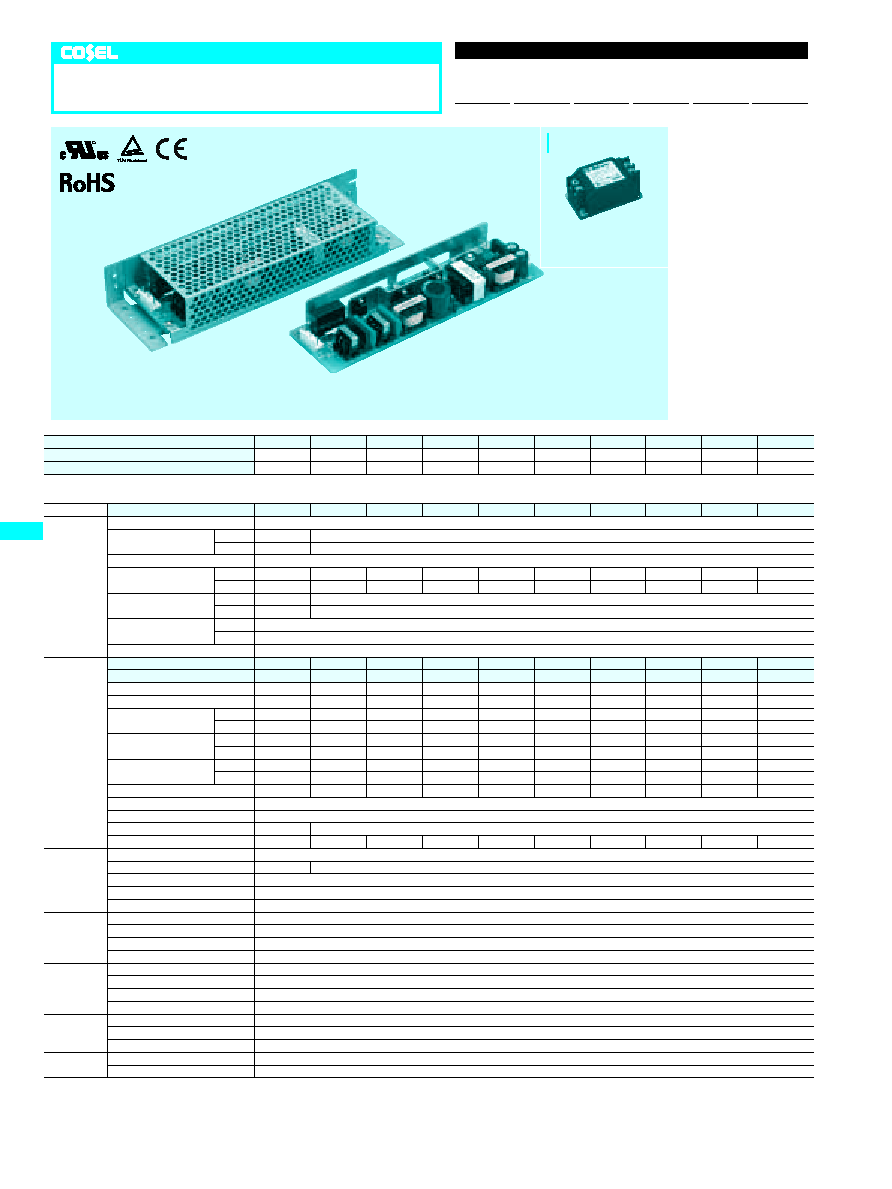
LEA50F
Rugged PCB type
LEA
50
F
-5
-
O
Ordering information
1
Series name
2
Output wattage
3
Universal input
4
Output voltage
5
Optional
C :with Coating
G :Low leakage current
J2:Mini terminal block
R :with Remote ON/OFF
S :with Chassis
SN :with Chassis & cover
Y :with Potentiometer
R
1
2
3
4
5
LEA
E-18
Recommended Noise Filter
NAC-06-472
High voltage pulse noise type : NAP series
Low leakage current type : NAM series
*The Noise Filter is recommended
*
to connect with several devices.
�
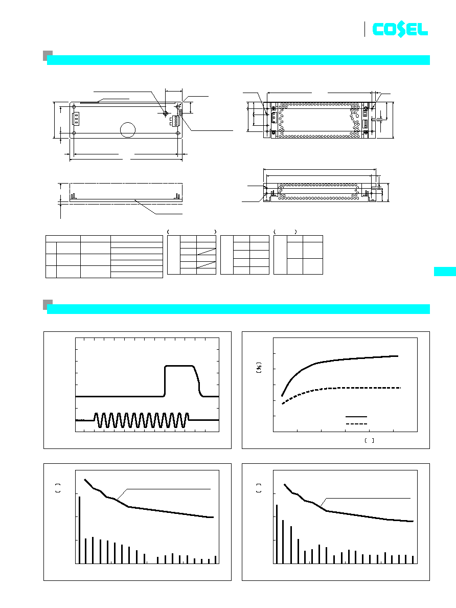
INPUT HARMONIC CURRENT (LEA50F-5)
�
EFFICIENCY (LEA50F-5)
�
INPUT HARMONIC CURRENT (LEA50F-5)
�
RISE TIME & FALL TIME (LEA50F-5)
DC Output
AC Input
Io=100%
50ms/DIV
ACIN 100V
EFFICIENCY
INPUT VOLTAGE
V
Load factor
Input voltage AC
Harmonic current standard class A
(at odd number)
100%
100V
Load factor
Input voltage AC
Harmonic current standard class A
(at odd number)
100%
230V
HARMONIC ORDER
HARMONIC ORDER
HARMONIC CURRENT
A
HARMONIC CURRENT
A
100
140
180
220
260
300
60
68
70
72
74
76
78
80
0
30
40
0.001
0.01
0.1
1
10
10
20
0
10
0.001
0.01
0.1
1
10
20
30
40
100%
50%
Load factor
Load factor
LEA
E-19
LEA50F
External view
�
Keep drawing current per pin below 5A for CN2
�
Weight: 210g or less
PIN CONNECTION
Pin No.
1
2
3
4
5
Input
AC(L)
AC(N)
FG
CN1
Pin No. Output
CN2
Optional
1
2
3
4
-
V
-
V
+
V
+
V
Pin No. Remote ON/OFF
CN3
1
2
RC(
+
)
RC(
-
)
(Without chassis and cover)
�
Tolerance:
t
1
�
Dimensions in mm.
�
PCB Material: Glass composite
�
Chassis and cover is optional.
�
Mounting torque: 0.6N
�
m(6.3kg f
�
cm)max
(CEM3)
0.5
Connector for Remote
ON/OFF (optional)
Voltage adjust (optional)
Name plate
Mounting
Hole
Mounting Hole
23
17.5
22
7
3.5
65
32
12
225
36
15
10
3.5
7
4-
�
3.5
2-
�
3.5
�
3.5
195
5
55
185+
-0.5
210+
-0.5
210+
-0.5
40
+
-
0.5
20
+
-
45
+
-
0.5
CN2
C119
CN3
CN1
FG
AC(N)
AC(L)
Output(-)
Output(+)
RC(-)
RC(+)
4-M3
CN3
CN2
CN1
Mounting Hole
2-M3
5
(Lead)
23
PCB t=1.6
3
ma
x
I / O Connector Mating Connector
Terminal
(Mfr: J.S.T.)
CN1
CN2
CN3
B3P5-VH
B4P-VH
B2B-XH-A
VHR-5N
VHR-4N
XHP-2
Chain : SVH-21T-P1.1
Loose: BVH-21T-P1.1
Chain : SVH-21T-P1.1
Loose: BVH-21T-P1.1
Chain : SXH-001T-P0.6
Loose: BXH-001T-P0.6
Performance data
MODEL
LEA75F-3R3-Y LEA75F-5
LEA75F-9
LEA75F-12 LEA75F-15 LEA75F-18 LEA75F-24 LEA75F-24-H LEA75F-30 LEA75F-48
MAX OUTPUT WATTAGE[W]
49.5
75
76.5
75.6
75
75.6
76.8
76.8
75
76.8
DC OUTPUT
*
5
3.3V 15A
5V 15A
9V 8.5A
12V 6.3A
15V 5A
18V 4.2A
24V 3.2A
24V 3.2(3.8)A 30V 2.5A
48V 1.6A
SPECIFICATIONS
MODEL
LEA75F-3R3-Y LEA75F-5
LEA75F-9
LEA75F-12 LEA75F-15 LEA75F-18 LEA75F-24 LEA75F-24-H LEA75F-30 LEA75F-48
INPUT
VOLTAGE[V]
AC85 - 264 1
f
or DC120 - 370
CURRENT[A]
ACIN 100V 0.8
1.1typ
ACIN 200V 0.4
0.55typ
FREQUENCY[Hz]
50/60 (47 - 63) or DC
EFFICIENCY[%]
ACIN 100V 70typ
75typ
78typ
78typ
79typ
81typ
82typ
82typ
82typ
84typ
ACIN 200V 71typ
77typ
80typ
80typ
81typ
83typ
84typ
84typ
84typ
86typ
POWER FACTOR
ACIN 100V 0.98typ
0.99typ
ACIN 200V 0.92typ
0.94typ
INRUSH CURRENT[A]
ACIN 100V 15typ (Io=100%) (At cold start) (Ta=25
C
)
ACIN 200V 30typ (Io=100%) (At cold start) (Ta=25
C
)
LEAKAGE CURRENT[mA]
0.75max (60Hz, According to IEC60950 and DEN-AN)
OUTPUT
VOLTAGE[V]
3.3
5
9
12
15
18
24
24
30
48
CURRENT[A]
*
1
15
15
8.5
6.3
5
4.2
3.2
3.2 (Peak 3.8)
2.5
1.6
LINE REGULATION[mV]
20max
20max
36max
48max
60max
72max
96max
96max
120max
192max
LOAD REGULATION[mV]
40max
40max
100max
100max
120max
120max
150max
150max
180max
300max
RIPPLE[mVp-p]
0 to +50
C
*
2
80max
80max
120max
120max
120max
120max
120max
120max
120max
150max
-10 - 0
C
*
2
140max
140max
160max
160max
160max
160max
160max
160max
160max
200max
RIPPLE NOISE[mVp-p]
0 to +50
C
*
2
120max
120max
150max
150max
150max
150max
150max
150max
150max
350max
-10 - 0
C
*
2
160max
160max
180max
180max
180max
180max
180max
180max
180max
400max
TEMPERATURE REGULATION[mV]
0 to +50
C
50max
50max
90max
120max
150max
180max
240max
240max
300max
480max
-10 to +50
C
60max
60max
120max
150max
180max
200max
290max
290max
360max
600max
DRIFT[mV]
*
3
20max
20max
36max
48max
60max
72max
96max
96max
120max
192max
START-UP TIME[ms]
500max (ACIN 100V, Io=100%)
HOLD-UP TIME[ms]
20typ (Io=100%)
OUTPUT VOLTAGE ADJUSTMENT RANGE[V]
2.85 - 3.6
Fixed ("Y"which can be adjusted the output is available as optional:
t
10%)
OUTPUT VOLTAGE SETTING[V]
3.25 - 3.35
4.9 - 5.3
8.6 - 9.4
11.5 - 12.5
14.4 - 15.6
17.3 - 18.7
23.0 - 25.0
23.0 - 25.0
28.5 - 31.5
46.0 - 50.0
PROTECTION
CIRCUIT AND
OTHERS
OVERCURRENT PROTECTION
Works over 105% of rating (works over 105% of peak current at option -H) and recovers automatically
OVERVOLTAGE PROTECTION
4.00 - 5.25V Works at 115 - 140% of rating
OPERATING INDICATION
Not provided
REMOTE SENSING
Not provided
REMOTE ON/OFF
Option (Refer to Instruction Manual)
ISOLATION
INPUT-OUTPUT
-
RC
*
4
AC3,000V 1minute, Cutoff current = 10mA, DC500V 50M
W
min (At Room Temperature)
INPUT-FG
AC2,000V 1minute, Cutoff current = 10mA, DC500V 50M
W
min (At Room Temperature)
OUTPUT
-
RC-FG
*
4
AC500V 1minute, Cutoff current = 100mA, DC500V 50M
W
min (At Room Temperature)
OUTPUT-RC
*
4
AC100V 1minute, Cutoff current = 100mA, DC100V 10M
W
min (At Room Temperature)
ENVIRONMENT
OPERATING TEMP.,HUMID.AND ALTITUDE
-10 to +70
C
, 20 - 90%RH (Non condensing) (Refer to DERATING CURVE), 3,000m (10,000feet) max
STORAGE TEMP.,HUMID.AND ALTITUDE
-20 to +75
C
, 20 - 90%RH (Non condensing), 9,000m (30,000feet) max
VIBRATION
10 - 55Hz, 19.6m/s
2
(2G), 3minutes period, 60minutes each along X, Y and Z axis
IMPACT
196.1m/s
2
(20G), 11ms, once each X, Y and Z axis
SAFETY AND
NOISE
REGULATIONS
AGENCY APPROVALS
UL60950-1, C-UL, EN60950-1, EN50178 Complies with DEN-AN and IEC60950-1 (At only AC input)
CONDUCTED NOISE
Complies with FCC-B, CISPR22-B, EN55022-B, VCCI-B
HARMONIC ATTENUATOR
Complies with IEC61000-3-2
OTHERS
CASE SIZE/WEIGHT
55
X
32
X
222mm (W
X
H
X
D) /290g max (without chassis and cover)
COOLING METHOD
Convection
*
1
Peak load for 10 sec. or less is acceptable if the total wattage is less than the rated wattage.
*
2
This is the value that measured on measuring board with capacitor of 22
m
F within 150mm
from output terminal.
Measured by 20MHz oscilloscope or Ripple-Noise meter (Equivalent to KEISOKU-GIKEN:
RM101).
*
3
Drift is the change in DC output for an eight hour period after a half-hour warm-up at 25
C
,
with the input voltage held constant at the rated input/output.
*
4
Applicable when remote control (optional) is added.
*
5
( ):peak current.
*
Parallel operation with other model is not possible.
*
Derating is required when operated with chassis and cover.
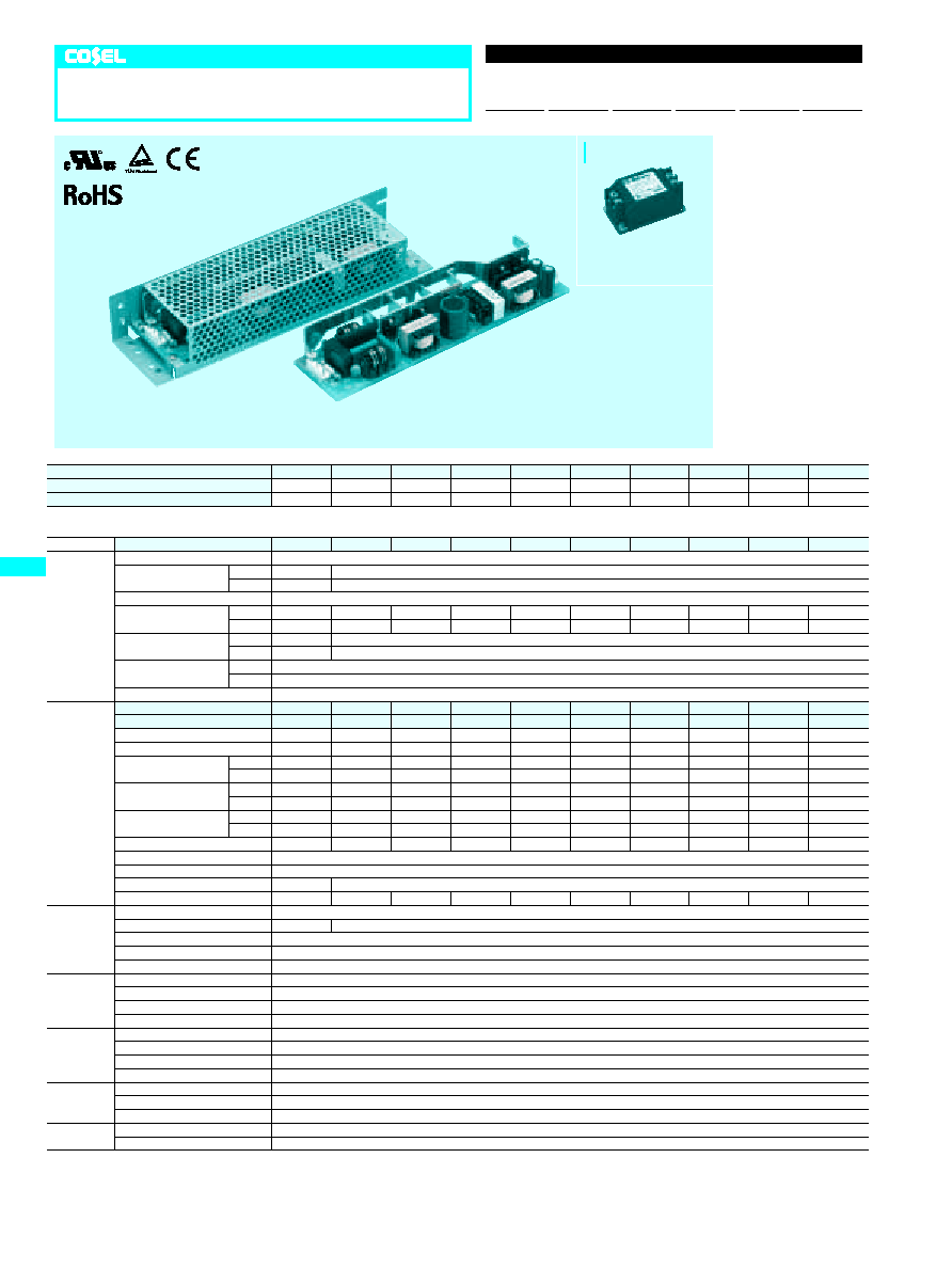
LEA75F
Rugged PCB type
LEA
75
F
-5
-
O
Ordering information
1
Series name
2
Output wattage
3
Universal input
4
Output voltage
5
Optional
C :with Coating
G :Low leakage current
J2:Mini terminal block
R :with Remote ON/OFF
S :with Chassis
SN :with Chassis & cover
Y :with Potentiometer
R
1
2
3
4
5
LEA
E-20
Recommended Noise Filter
NAC-06-472
High voltage pulse noise type : NAP series
Low leakage current type : NAM series
*The Noise Filter is recommended
*
to connect with several devices.

�
INPUT HARMONIC CURRENT (LEA75F-5)
�
EFFICIENCY (LEA75F-5)
�
INPUT HARMONIC CURRENT (LEA75F-5)
�
RISE TIME & FALL TIME (LEA75F-5)
DC Output
AC Input
Io=100%
50ms/DIV
ACIN 100V
78
80
76
74
72
100
60
140
180
220
260
300
100%
50%
Load factor
Load factor
EFFICIENCY
INPUT VOLTAGE
V
Load factor
Input voltage AC
Harmonic current standard class A
(at odd number)
100%
100V
HARMONIC ORDER
HARMONIC CURRENT
A
0
10
20
30
40
0.01
0.001
0.1
1
10
Load factor
Input voltage AC
Harmonic current standard class A
(at odd number)
100%
230V
HARMONIC ORDER
HARMONIC CURRENT
A
0
30
40
0.001
0.01
0.1
1
10
10
20
LEA
E-21
LEA75F
External view
I / O Connector Mating Connector
Terminal
(Mfr: J.S.T.)
CN1
CN2
CN3
B3P5-VH
B6P-VH
B2B-XH-A
VHR-5N
VHR-6N
XHP-2
Chain : SVH-21T-P1.1
Loose: BVH-21T-P1.1
Chain : SVH-21T-P1.1
Loose: BVH-21T-P1.1
Chain : SXH-001T-P0.6
Loose: BXH-001T-P0.6
�
Keep drawing current per pin below 5A for CN2
�
Weight: 290g or less
�
Tolerance: 1
�
Dimensions in mm.
�
PCB Material: Glass composite
�
Chassis and cover is optional.
�
Chassis and cover is not available
to remote ON/OFF unit.
�
Mounting torque: 1.5N
�
m(16kgf
�
cm)max
PIN CONNECTION
Pin No.
1
2
3
4
5
Input
AC(L)
AC(N)
FG
CN1
Pin No. Output
CN2
Optional
Pin No. Remote ON/OFF
CN3
1
2
RC(
+
)
RC(
-
)
1
~
3
4
~
6
-
V
+
V
(Without chassis and cover)
(CEM3)
Connector for Remote
ON/OFF (optional)
Voltage adjust (optional)
Name plate
(Lead)
Mounting
Hole
Mounting Hole
22
8
4.5
65
32
12
252
42
15
15
4.5
8
4-
�
3.5
35.5
2-
�
4.5
�
4.5
222
29
5
55
212+
-0.5
235+
-0.5
235+
-0.5
40
+
-
0.5
20
+
-
0.5
45
+
-
0.5
CN2
C119
PCB t=1.6
CN3
CN1
FG
AC(N)
AC(L)
Output(-)
Output(+)
3
ma
x
4-M4
CN1
CN2
Mounting Hole
2-M4
5
RC(-)
RC(+)
12.5
t
Performance data

MODEL
LEA100F-3R3-Y LEA100F-5 LEA100F-9 LEA100F-12 LEA100F-15 LEA100F-18 LEA100F-24 LEA100F-24-H LEA100F-30 LEA100F-48
MAX OUTPUT WATTAGE[W]
66
100
103.5
102
100.5
100.8
103.2
103.2
105
105.6
DC OUTPUT
*
5
3.3V 20A
5V 20A
9V 11.5A
12V 8.5A
15V 6.7A
18V 5.6A
24V 4.3A
24V 4.3(5.0)A 30V 3.5A
48V 2.2A
SPECIFICATIONS
MODEL
LEA100F-3R3-Y LEA100F-5 LEA100F-9 LEA100F-12 LEA100F-15 LEA100F-18 LEA100F-24 LEA100F-24-H LEA100F-30 LEA100F-48
INPUT
VOLTAGE[V]
AC85 - 264 1
f
or DC120 - 370
CURRENT[A]
ACIN 100V 1.0
1.4typ
ACIN 200V 0.5
0.7typ
FREQUENCY[Hz]
50/60 (47 - 63) or DC
EFFICIENCY[%]
ACIN 100V 71typ
75typ
79typ
79typ
79typ
81typ
81typ
81typ
82typ
83typ
ACIN 200V 73typ
78typ
81typ
81typ
82typ
83typ
84typ
84typ
85typ
85typ
POWER FACTOR
ACIN 100V 0.98typ
0.99typ
ACIN 200V 0.92typ
0.94typ
INRUSH CURRENT[A]
ACIN 100V 15typ (Io=100%) (At cold start) (Ta=25
C
)
ACIN 200V 30typ (Io=100%) (At cold start) (Ta=25
C
)
LEAKAGE CURRENT[mA]
0.75max (60Hz, According to IEC60950 and DEN-AN)
OUTPUT
VOLTAGE[V]
3.3
5
9
12
15
18
24
24
30
48
CURRENT[A]
*
1
20
20
11.5
8.5
6.7
5.6
4.3
4.3 (Peak 5.0)
3.5
2.2
LINE REGULATION[mV]
20max
20max
36max
48max
60max
72max
96max
96max
120max
192max
LOAD REGULATION[mV]
40max
40max
100max
100max
120max
120max
150max
150max
180max
300max
RIPPLE[mVp-p]
0 to +50
C
*
2
80max
80max
120max
120max
120max
120max
120max
120max
120max
150max
-10 - 0
C
*
2
140max
140max
160max
160max
160max
160max
160max
160max
160max
200max
RIPPLE NOISE[mVp-p]
0 to +50
C
*
2
120max
120max
150max
150max
150max
150max
150max
150max
150max
350max
-10 - 0
C
*
2
160max
160max
180max
180max
180max
180max
180max
180max
180max
400max
TEMPERATURE REGULATION[mV]
0 to +50
C
50max
50max
90max
120max
150max
180max
240max
240max
300max
480max
-10 to +50
C
60max
60max
120max
150max
180max
200max
290max
290max
360max
600max
DRIFT[mV]
*
3
20max
20max
36max
48max
60max
72max
96max
96max
120max
192max
START-UP TIME[ms]
500max (ACIN 100V, Io=100%)
HOLD-UP TIME[ms]
20typ (Io=100%)
OUTPUT VOLTAGE ADJUSTMENT RANGE[V]
2.85 - 3.6
Fixed ("Y"which can be adjusted the output is available as optional:
t
10%)
OUTPUT VOLTAGE SETTING[V]
3.25 - 3.35
4.9 - 5.3
8.6 - 9.4
11.5 - 12.5
14.4 - 15.6
17.3 - 18.7
23.0 - 25.0
23.0 - 25.0
28.5 - 31.5
46.0 - 50.0
PROTECTION
CIRCUIT AND
OTHERS
OVERCURRENT PROTECTION
Works over 105% of rating (works over 105% of peak current at option -H) and recovers automatically
OVERVOLTAGE PROTECTION
4.00 - 5.25V Works at 115 - 140% of rating
OPERATING INDICATION
Not provided
REMOTE SENSING
Not provided
REMOTE ON/OFF
Option (Refer to Instruction Manual)
ISOLATION
INPUT-OUTPUT
-
RC
*
4
AC3,000V 1minute, Cutoff current = 10mA, DC500V 50M
W
min (At Room Temperature)
INPUT-FG
AC2,000V 1minute, Cutoff current = 10mA, DC500V 50M
W
min (At Room Temperature)
OUTPUT
-
RC-FG
*
4
AC500V 1minute, Cutoff current = 100mA, DC500V 50M
W
min (At Room Temperature)
OUTPUT-RC
*
4
AC100V 1minute, Cutoff current = 100mA, DC100V 10M
W
min (At Room Temperature)
ENVIRONMENT
OPERATING TEMP.,HUMID.AND ALTITUDE
-10 to +70
C
, 20 - 90%RH (Non condensing) (Refer to DERATING CURVE), 3,000m (10,000feet) max
STORAGE TEMP.,HUMID.AND ALTITUDE
-20 to +75
C
, 20 - 90%RH (Non condensing), 9,000m (30,000feet) max
VIBRATION
10 - 55Hz, 19.6m/s
2
(2G), 3minutes period, 60minutes each along X, Y and Z axis
IMPACT
196.1m/s
2
(20G), 11ms, once each X, Y and Z axis
SAFETY AND
NOISE
REGULATIONS
AGENCY APPROVALS
UL60950-1, C-UL, EN60950-1, EN50178 Complies with DEN-AN and IEC60950-1 (At only AC input)
CONDUCTED NOISE
Complies with FCC-B, CISPR22-B, EN55022-B, VCCI-B
HARMONIC ATTENUATOR
Complies with IEC61000-3-2
OTHERS
CASE SIZE/WEIGHT
62
X
35
X
222mm (W
X
H
X
D) /380g max (without chassis and cover)
COOLING METHOD
Convection
*
1
Peak load for 10 sec. or less is acceptable if the total wattage is less than the rated wattage.
*
2
This is the value that measured on measuring board with capacitor of 22
m
F within 150mm
from output terminal.
Measured by 20MHz oscilloscope or Ripple-Noise meter (Equivalent to KEISOKU-GIKEN:
RM101).
*
3
Drift is the change in DC output for an eight hour period after a half-hour warm-up at 25
C
,
with the input voltage held constant at the rated input/output.
*
4
Applicable when remote control (optional) is added.
*
5
( ):peak current.
*
Parallel operation with other model is not possible.
*
Derating is required when operated with chassis and cover.
LEA100F
Rugged PCB type
LEA 100
F
-5
-
O
Ordering information
1
Series name
2
Output wattage
3
Universal input
4
Output voltage
5
Optional
C :with Coating
G :Low leakage current
J2:Mini terminal block
R :with Remote ON/OFF
S :with Chassis
SN :with Chassis & cover
Y :with Potentiometer
R
1
2
3
4
5
LEA
E-22
Recommended Noise Filter
NAC-06-472
High voltage pulse noise type : NAP series
Low leakage current type : NAM series
*The Noise Filter is recommended
*
to connect with several devices.