 | –≠–ª–µ–∫—Ç—Ä–æ–Ω–Ω—ã–π –∫–æ–º–ø–æ–Ω–µ–Ω—Ç: KAQV213H | –°–∫–∞—á–∞—Ç—å:  PDF PDF  ZIP ZIP |
PRODUCT SPECIFICATION
DATE03/01/2005
Preliminary
cosmo
ELECTRONICS CORPORATION
SOLID STATE RELAY - MOSFET OUTPUT
KAQV213H
SHEET 1 OF 7
REV.
0
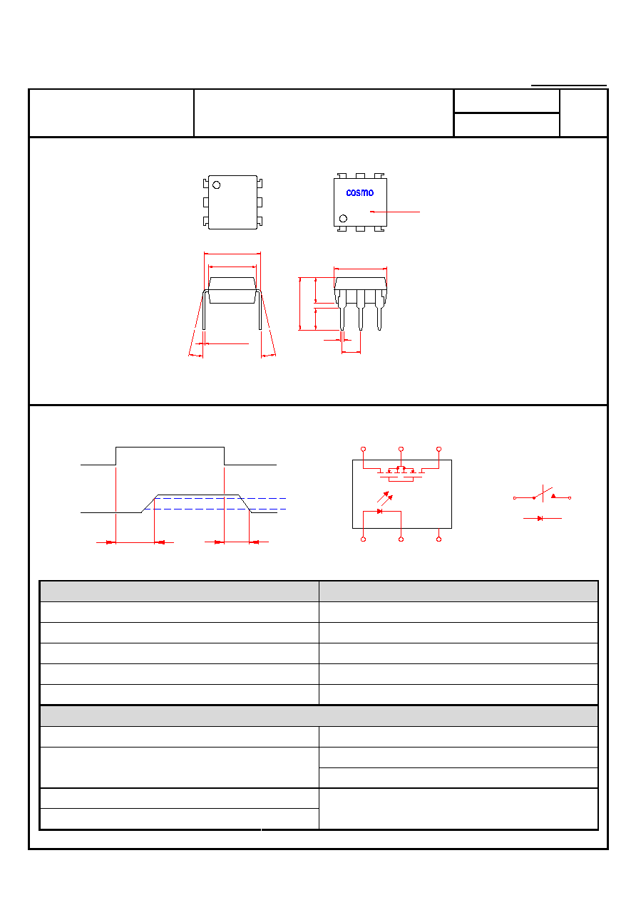
OUTSIDE DIMENSION
0.254±0.05
13.0∞
7.62
6.50
13.0∞
2.54
3.
5
2.
7
6.
9
0.5
XXX
7.3
Date Code
V213H
Turn On / Turn Off time
Output
T
ON
Input
T
OFF
90%
10%
2
1
6
5
3
5,6
4
4
1 FORM A
NORMALLY OPEN
Absolute Maximum Ratings
Ta=25
EmitterInput
DetectorOutput
Reverse Voltage .................................... 5.0V Output Breakdown Voltage ..................... ± 250V
Continuous Forward Current ..................
50mA Continuous Load Current ..................
± 200mA
Peak Forward Current ................................. 1A Power Dissipation ..............................
500mW
Power Dissipation ..............................
100mW
Derate Linearly from 25 ...............
1.3mW/
General Characteristics
Isolation Test Voltage .................. 5000VACrms Storage Temperature Range ...... -40 to +125
Operating Temperature Range ...
-40 to +85
Isolation Resistance
Vio=500VTa=25 ........................... 10
10
Junction Temperature ...........................
100
Total Power Dissipation ........................ 550mW
Derate Linearly from 25 ...............
2.5mW/
Soldering Temperature
2mm from case10 sec ........................ 260
Unitmm
Tolerance±0.2mm
PRODUCT SPECIFICATION
DATE03/01/2005
Preliminary
cosmo
ELECTRONICS CORPORATION
SOLID STATE RELAY - MOSFET OUTPUT
KAQV213H
SHEET 2 OF 7
REV.
0
Electro-optical Characteristics
Ta=25
Parameter
Symbol
Conditions
Min. Typ. Max. Unit.
EmitterInput
Forward Voltage
V
F
I
F
=10mA
1.2
1.5
V
Operation Input Current
IF
ON
V
L
=±20VI
L
=100mAt=10ms
5.0
mA
Recovery Input Current
IF
OFF
V
L
=±20VI
L
5µA
0.2 mA
DetectorOutput
Output Breakdown Voltage
V
B
I
B
=50µA 250
V
Output Off-State Leakage
IT
OFF
V
T
=100VI
F
=0mA
0.2 1 A
I/O Capacitance
C
ISO
I
F
=0f=1MHz
6 pF
A
8
B
4
ON Resistance Connection
C
R
ON
I
L
=100mAI
F
=10mA
2
Turn-On Time
T
ON
0.3
1.0
ms
Turn-Off Time
T
OFF
I
F
=10mAV
L
=±20V
t=10msI
L
=±100mA
0.7
1.5
ms
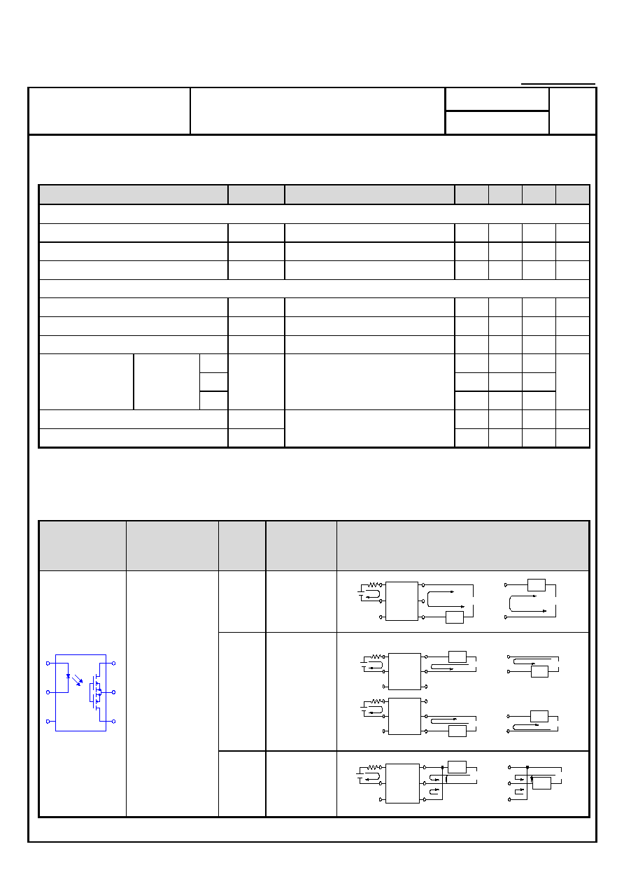
Schematic and Wiring Diagrams
Schematic
Output
Configuration
Load Connection
Wiring Diagrams
AC/DC
A
V
2
3
IN
I
F
1
5
4
6
L
I
Load
V (AC,DC)
L
I
L
4
6
Load
(AC,DC)
L
V
DC B
+
I
Load
6
4
5
I
L
6
4
5
L
V
Load
(DC)
-
+
L
V (DC)
-
L
+
6
4
5
Load
I
L
5
Load
L
I
L
V (DC)
-
+
L
V (DC)
-
1
V
V
F
I
3
2
IN
IN
I
F
1
3
2
3
2
1
4
5
6
1a
DC C
+
I
6
+
Load
6
1
V
IN
I
F
3
2
4
5
V
I
L
(DC)
-
L
4
5
Load
L
(DC)
L
V
-
PRODUCT SPECIFICATION
DATE03/01/2005
Preliminary
cosmo
ELECTRONICS CORPORATION
SOLID STATE RELAY - MOSFET OUTPUT
KAQV213H
SHEET 3 OF 7
REV.
0
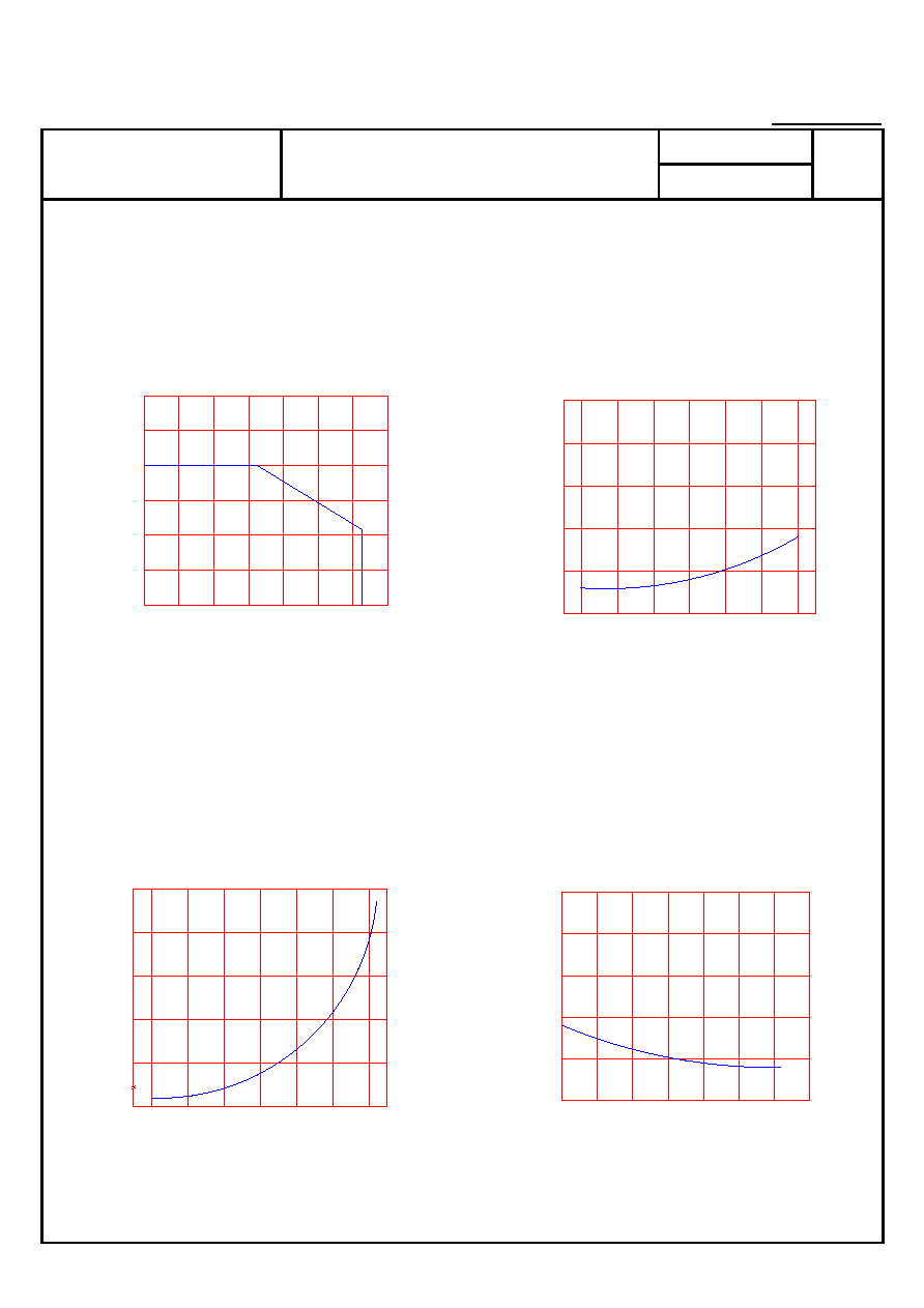
Data Curve
Load current vs. ambient temperature
Allowable ambient Temperature
-40 to +85
On resistance vs. ambient temperature
across terminals 4 and 6 pin
LED current5mA
Continuous load current200mADC
Load current
mA
0
-40 -20
0
20 40 60
100
80
50
300
150
100
200
250
On resist
ance
0
20
-20
-40
0
60
40
80
50
10
20
40
30
Ambient temperature Ta
Ambient temperature Ta
Turn On Time vs. ambient temperature
Load voltage 250VDC
LED current5mA
Continuous load current200mADC
Turn Off Time vs. ambient temperature
Load voltage 250VDC
LED current5mA
Continuous load current200mADC
T
u
rn On T
i
me
ms
80
60
40
0
-40 -20
20
0
1.2
0.4
0.6
0.8
1.0
T
u
rn Off T
i
me
ms
100
80
60
40
20
0
-20
-40
0
2.5
0.5
1.0
1.5
2.0
Ambient temperature Ta
Ambient temperature Ta

PRODUCT SPECIFICATION
DATE03/01/2005
Preliminary
cosmo
ELECTRONICS CORPORATION
SOLID STATE RELAY - MOSFET OUTPUT
KAQV213H
SHEET 4 OF 7
REV.
0
LED operate current vs.
ambient temperature
Load Voltage250VDC
Continuous load current200mADC
LED Turn Off current vs.
ambient temperature
Load Voltage250VDC
Continuous load current200mADC
LED operate current
mA
-40
0
1
3
2
4
-20
0
20 40
5
60 80
LED T
u
rn Off current
mA
0
1
-20
-40
3
2
4
5
80
40
0
20
60
Ambient temperature Ta
Ambient temperature Ta
LED dropout voltage vs.
ambient temperature
LED current5 to 50mA
Voltage vs. current characteristics
of output at MOSFET portion
Measured portionacross terminals
4 and 6 pin
Ambient temperature25
LED dropout volt
age
V
80
-20
-40
0
20 40 60
1.9
1.3
0
0.9
1.1
1.7
1.5
100
5mA
50mA
10mA
20mA
30mA
V
o
lt
age VS. Current
Characteristics
-2
Cu
rr
ent mA
-4
-5
-3
Voltage V
5
4
2 3
1
-1
50
250
300
200
150
100
-50
-100
-150
-300
-250
-200
Ambient temperature Ta Ambient
temperature25

PRODUCT SPECIFICATION
DATE03/01/2005
Preliminary
cosmo
ELECTRONICS CORPORATION
SOLID STATE RELAY - MOSFET OUTPUT
KAQV213H
SHEET 5 OF 7
REV.
0
LED forward current vs. Turn On Time
Across terminals 4 and 6pin
Load voltage250VDC
Continuous load current200mADC
Ambient temperature25
Off state leakage current
Across terminals 4and 6 pin
Ambient temperature25
T
u
rn On T
i
me
ms
0
0
10
20
30
40
50
60
0.5
1.0
1.5
2.0
Off st
ate leakage cu
rrent
10
40
0
20
60
80
100
-12
-9
10
-6
10
-3
10
LED forward currentmA Load
voltageV
LED forward current vs. reverse(ON) time
Across terminals 4 and 6 pin
Load voltage250VDC
Continuous load current200mADC
Ambient temperature25
Applied voltage vs. output capacitance
Across terminals 4 and 6 pin
Frequency1MHz
Ambient temperature25
T
u
rn Off T
i
me
ms
0
0
10
20
30
40
50
1.5
0.5
1.0
2.5
2.0
60
Output cap
acit
a
nce
pF
0
0
10
20
30
40
50
60
10
20
30
40
50
LED forward currentmA Applied
voltageV
PRODUCT SPECIFICATION
DATE03/01/2005
Preliminary
cosmo
ELECTRONICS CORPORATION
SOLID STATE RELAY - MOSFET OUTPUT
KAQV213H
SHEET 6 OF 7
REV.
0
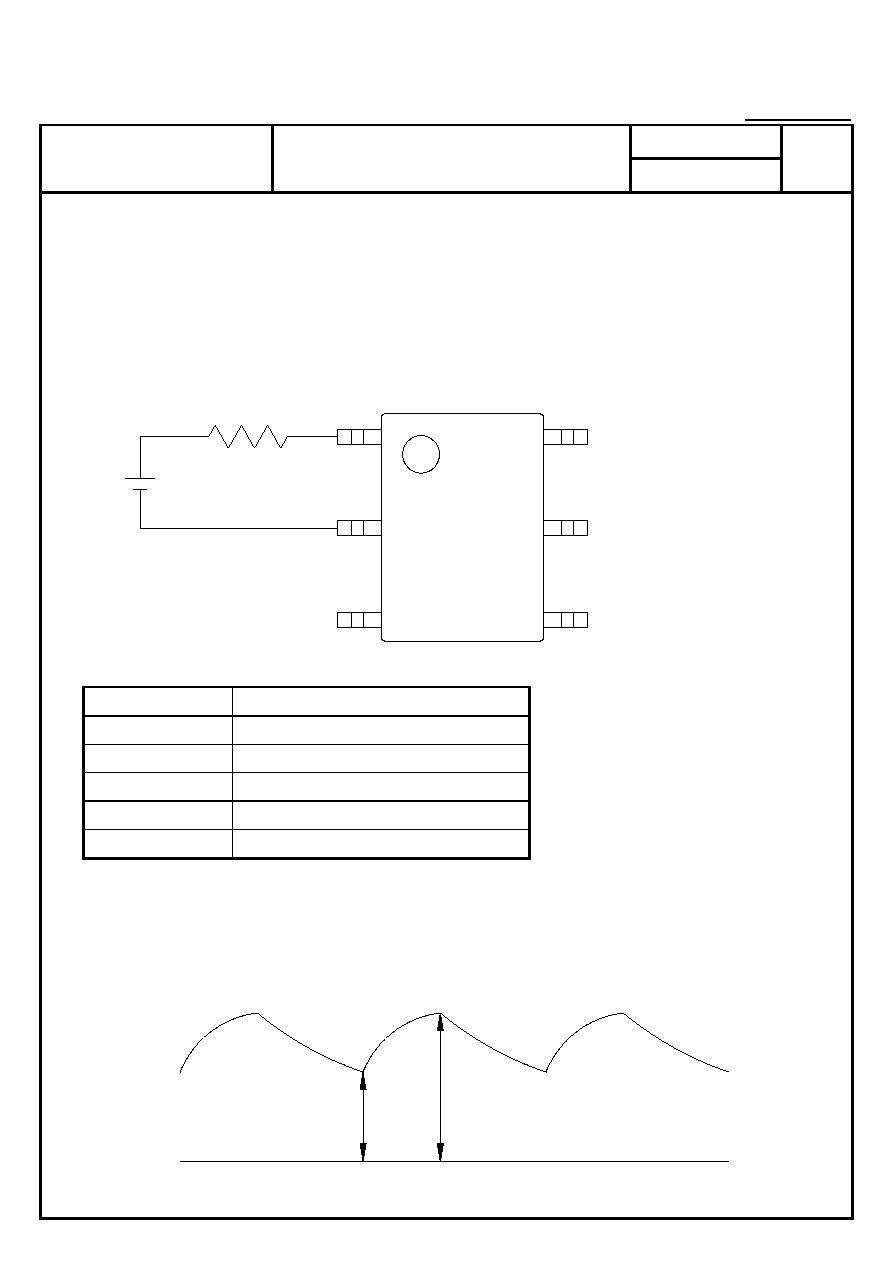
USING METHODS
Examples of resistance value to
control LED forward currentIF
SSR-MOSFET OUTPUT
IF=5mA
E
R
3
2
1
4
5
6
E R
3.3V Approx.
330
5V Approx.
640
12V Approx.
1.9K
15V Approx.
2.5K
24V Approx.
4.1K
1 LED forward current must be more than 5mAat E min.
2 LED forward current must be less than 50mAat E max.
Emin.
Emax.

PRODUCT SPECIFICATION
DATE03/01/2005
Preliminary
cosmo
ELECTRONICS CORPORATION
SOLID STATE RELAY - MOSFET OUTPUT
KAQV213H
SHEET 7 OF 7
REV.
0
USING METHODS
Regulate the spike voltage generated on the inductive
load as follows
Load
4
3
6
5
1
2
R-C Snubber
Load
5
2
4
3
6
1