 | –≠–ª–µ–∫—Ç—Ä–æ–Ω–Ω—ã–π –∫–æ–º–ø–æ–Ω–µ–Ω—Ç: D2410PG | –°–∫–∞—á–∞—Ç—å:  PDF PDF  ZIP ZIP |
M O D E L N U M B E R S
AC CONTROL
A1210
A1225
A1240
A2410
A2425
A2450
A2475
A2490
D C C ONTROL
D1210
D1225
D1240
D2410
D2425
D2450
D2475
D2490
OUTPUT SPECIFICATIONS
Operating Voltage (47-63 Hz) [Vrms]
24-140
24-140
24-140
24-280
24-280
24-280
24-280
24-280
Max. Load Current
[Arms]
10
25
40
10
25
50
75
90
Min. Load Current, [mArms]
40
40
40
40
40
40
40
40
Transient Overvoltage [Vpk]
400
400
400
600
600
600
600
600
Max. Surge Current, (16.6ms) [Apk]
120
250
625
120
250
625
1000
1200
Max. On-State Voltage Drop @ Rated Current [Vpk]
1.6
1.6
1.6
1.6
1.6
1.6
1.6
1.6
Thermal Resistance Junction to Case (R
JC) [∞C/W]
1.48
1.02
0.63
1.48
1.02
0.63
0.31
0.28
Maximum I2 t for Fusing, (8.3 msec.) [A2sec]
60
260
1620
60
260
1620
4150
6000
Max. Off-State Leakage Current @ Rated Voltage [mArms]
8
8
8
10
10
10
10
10
Min. Off-State dv/dt @ Max. Rated Voltage [V/µsec]
500
500
500
500
500
500
500
500
Max. Turn-On Time
1/2 Cycle (DC Control), 10.0 msec (AC Control)
Max. Turn-Off Time
1/2 Cycle (DC Control), 40.0 msec(AC Control)
Power Factor (Min.) with Max. Load
0.5
0.5
0.5
0.5
0.5
0.5
0.5
0.5
INPUT SPECIFICATIONS
DC CONTROL
AC CONTROL
AC CONTROL
( E S U F F I X )
Control Voltage Range
3-32 Vdc
90-280 Vrms (60Hz)
18-36 Vrms
Max. Reverse Voltage
-32 Vdc
---
---
Max. Turn-On Voltage
3.0 Vdc
90 Vrms
18 Vrms
Min. Turn-Off Voltage
1.0 Vdc
10 Vrms
4.0 Vrms
Nominal Input Impedance
1500 Ohms
60K Ohms
9.0K Ohms
Typical Input Current
3.4mA @ 5 Vdc, 20mA @ 28Vdc
2mA @ 120 Vrms, 4mA @ 240 Vrms
3mA @ 24 Vrms
GENERAL NOTES
All parameters at 25∫C unless otherwise specified.
Off-State dv/dt test method per EIA/NARM standard RS-443, paragraph 13.11.1
Heat sinking required, for derating curves see page 2.
Turn-on time for random turn-on versions is 0.02 msec (DC Control Models).
∑ Zero Voltage and Random
Turn-On Switching
∑ Panel Mount
∑ 600V Blocking Capability
∑ Internal Snubber
∑ 110 & 125A Models
Available
FastFax Document No. 151
SERIES1.032698, PAGE 1 OF 3
Featuring state-of-the-art Surface
Mount Technology, these SPST-NO
relays deliver proven reliability in the
most demanding applications. Output
consists of an SCR AC switch and is
available in zero-cross, random turn-
on (phase controllable) and normally
closed (Form B) versions with either
AC or DC input (coil) control.
Manufactured in Crydom's ISO 9002
Certified facility for optimum product
performance and reliability.
Series 1
10-90Amp ∑ 120, 240 Vac ∑ AC Output
©1998 CRYDOM CORP, Specifications subject to change without notice.
For recommended applications and more information contact:
USA: (800) 8 CRYDOM ∑ (800) 827-9366 ∑ (619) 715-7200 ∑ fax (619) 715-7280
Crydom Corp, 9525 Chesapeake Drive, San Diego, CA 92123 ∑ e-mail: sales@crydom.com
WEB SITE: http://www.crydom.com FASTFAX Product Information: (888) 267-9191
UK: (44)1202 812300 ∑ fax (44)1202 812340 Crydom International Ltd., 85, Condor Close,
Woolsbridge Industrial Estate, Three-Legged Cross. Wimborne, Dorset, England BH21 6SU
GERMANY: (49)871 935405 ∑ fax (49)871 935407, Aussere Parkstr.5, D-84032 Altdorf, Germany
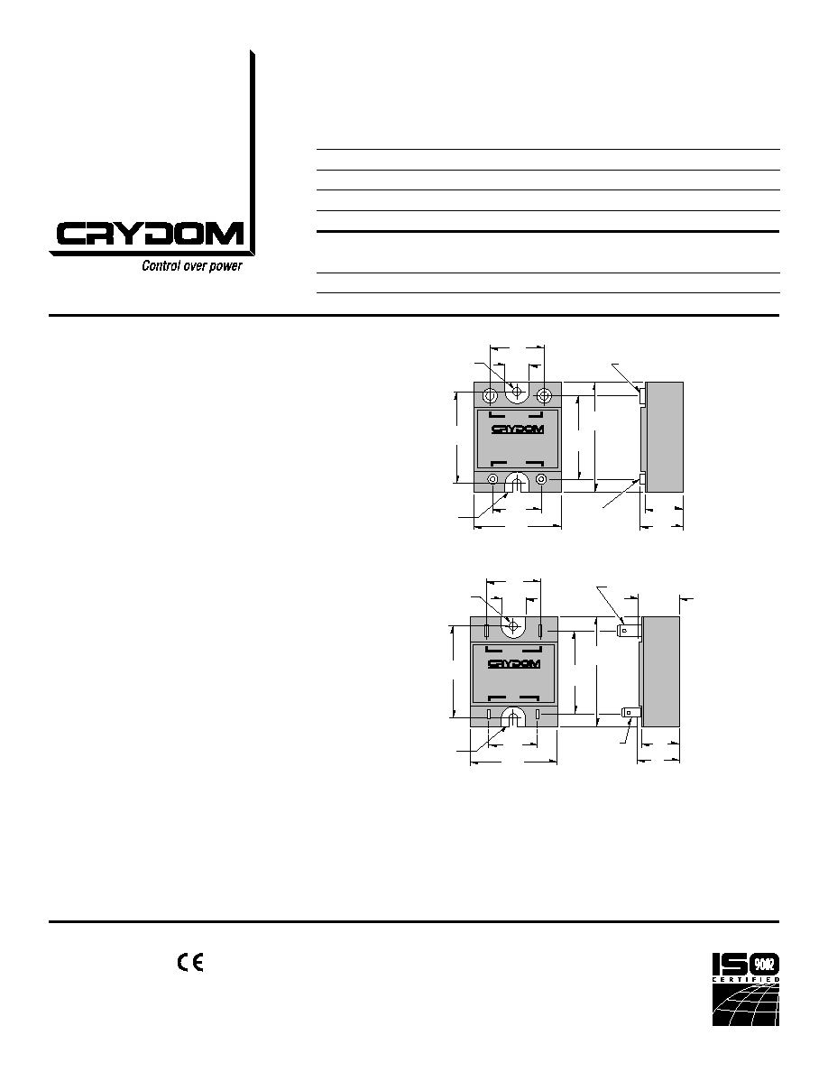
Screw Torque Requirements:
6-32 Screws - 10 in./lbs.,
8-32 and 10-32 Screws - 20in./lbs.
(Screws dry without grease.)
Fastons:
Single pair (up to 25A)
Double pair* (up to 50A).
*Caution: User must connect to both pairs
1.87
(47.5)
.78
(19.8)
2.30
(58.4)
1.70
(43.2)
.90
(22.9)
.45
(11.4)
1.10
(27.9)
8-32 TERMINAL
(2 PLACES )
1.00
(25.4)
6-32 TERMINAL
(2 PLACES)
1.80
(45.7)
SOLID-STATE RELAY
1
2
OUTPUT
3
4
+
--
INPUT
MOUNTING
HOLE/SLOT
0.17 (4.3) DIA.
BASE PLATE
.125 (3.2)
.90
(22.9)
FASTON
TERMINAL
.187 X .032
(2 PLCS.)
BASE PLATE
.125 (3.2)
FASTON TERMINAL
.250 X .032 (2 PLCS.)
1.87
(47.5)
.78
(19.8)
2.30
(58.4)
1.70
(43.2)
.87 REF.
(22.2)
1
2
OUTPUT
4
3
INPUT
1.00
(25.4)
1.80
(45.7)
.45
(11.4)
1.10
(27.9)
MOUNTING
HOLE/SLOT
0.17 (4.3) DIA.
Series 1
10-90Amp ∑ 120, 240 Vac ∑ AC Output
FastFax Document No.151
SERIES1.032698, PAGE 2 OF 3
AVAILABLE OPTIONS
-B
Normally Closed (Form B)
Example: D2450-B, A2450-B
4D
400 Hz Operation
10-50 Amp Models Only
Zero Cross Switching Only
Example: 4D2450
E
24 Vac Input (18-36 Vac)
Example: A2450E
-10
Random Turn-On (AC & DC Control)
Phase Controllable (DC Control)
Example: D2450-10
F
Faston Terminals (Up to 50A Models)
.250 x .032 Faston Terminals
Example: D1225F
GENERAL SPECIFICATIONS
Dielectric Strength 50/60Hz Input/Output/Base
4000 Vrms
Insulation Resistance (Min.) @ 500 Vdc
10
9
Ohm
Max. Capacitance Input/Output
8 pF
Ambient Operating Temperature Range
-40 to 80∫C
Ambient Storage Temperature Range
-40 to 125∫C
MECHANICAL SPECIFICATIONS
Weight: (typical)
3.0 oz. (86.5g)
Encapsulation:
Thermally Conductive Epoxy
Terminals:
Screws and Saddle Clamps Furnished, Unmounted
APPROVALS
UL
E116949
CSA
LR81689
VDE 10143 UG (Not Applicable: -B and 4D)
Crydom Heat Sinks offer excellent
thermal management and are per-
fectly matched to the load current rat-
ings of Crydom panel mount relays.
Request Crydom's Heat Sink specifica-
tion sheet for all the details.
©1998 CRYDOM CORP, Specifications subject to change without notice.
All dimensions are in inches (millimeters)
For recommended applications and more information contact:
USA: (800) 8 CRYDOM ∑ (800) 827-9366 ∑ (619) 715-7200 ∑ fax (619) 715-7280
Crydom Corp, 9525 Chesapeake Drive, San Diego, CA 92123 ∑ e-mail: sales@crydom.com
WEB SITE: http://www.crydom.com FASTFAX Product Information: (888) 267-9191
UK: (44)1202 812300 ∑ fax (44)1202 812340 Crydom International Ltd., 85, Condor Close,
Woolsbridge Industrial Estate, Three-Legged Cross. Wimborne, Dorset, England BH21 6SU
GERMANY: (49)871 935405 ∑ fax (49)871 935407, Aussere Parkstr.5, D-84032 Altdorf, Germany

12
8
4
0
2
4
8
10
6
20
40
60
80
Load Current [Arms]
Max Ambient Temp. [∫C]
Power Dissipation
110
115
120
Base Plate Temp [∫C]
10A
9∫C/W
5∫C/W
3∫C/W
7∫C/W
NO HEATSINK
30
20
10
25
15
5
0
5
10
20
25
15
20
40
60
80
Load Current [Arms]
Max Ambient Temp. [∫C]
Power Dissipation
95
120
Base Plate Temp [∫C]
25A
1∫C/W
100
110
3∫C/W
NO HEATSINK
60
40
20
0
10
20
40
50
30
20
40
60
80
Load Current [Arms]
Max Ambient Temp. [∫C]
Power Dissipation
90
Base Plate Temp [∫C]
50A
2∫C/W
1∫C/W
.5∫C/W
100
110
120
1.5∫C/W
NO HEATSINK
120
80
40
0
15
30
60
75
45
20
40
60
80
Load Current [Arms]
Max Ambient Temp. [∫C]
Power Dissipation
100
110
120
Base Plate Temp [∫C]
75A
.5∫C/W
95
1∫C/W
120
80
40
0
20
40
80
0
60
20
40
60
80
Load Current [Arms]
Max Ambient Temp. [∫C]
Power Dissipation
100
110
120
Base Plate Temp [∫C]
90A
1∫C/W
.4∫C/W
.2∫C/W
90
.5∫C/W
2∫C/W
.3∫C/W
Series 1
10-90Amp ∑ 120, 240 Vac ∑ AC Output
CURRENT DERATING CURVES
FastFax Document No.151
SERIES1.032698, PAGE 3 OF 3
©1998 CRYDOM CORP, Specifications subject to change without notice.
For recommended applications and more information contact:
USA: (800) 8 CRYDOM ∑ (800) 827-9366 ∑ (619) 715-7200 ∑ fax (619) 715-7280
Crydom Corp, 9525 Chesapeake Drive, San Diego, CA 92123 ∑ e-mail: sales@crydom.com
WEB SITE: http://www.crydom.com FASTFAX Product Information: (888) 267-9191
UK: (44)1202 812300 ∑ fax (44)1202 812340 Crydom International Ltd., 85, Condor Close,
Woolsbridge Industrial Estate, Three-Legged Cross. Wimborne, Dorset, England BH21 6SU
GERMANY: (49)871 935405 ∑ fax (49)871 935407, Aussere Parkstr.5, D-84032 Altdorf, Germany