24
15kV Isolation
Low Contact
Resistance
High Power
Switching
PCB or Panel
Mount
Flying Lead &
Solder Turret
Options
Excellent AC
Characteristics
D Series
15kV, 50W
Capable of withstanding voltages up to 15kV, the D-series High Voltage Reed
Relay is suitable for high reliability applications such as cardiac defibrillators,
test equipment and high voltage power supplies. Two contact materials are
available for low contact resistance or power switching applications.
Standard coil voltages of 5, 12 and 24 volts are available with form A and B
contact configurations.
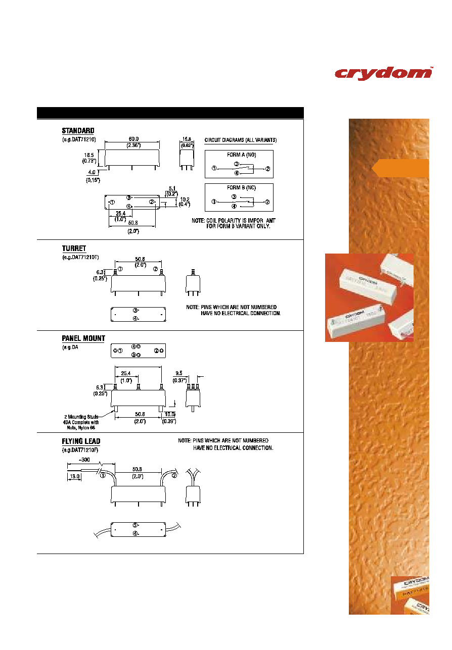
The D-series, range is now available with a new panel mounting option via nylon
studs, as well as a choice of electrical connection methods (solder turret tag and
flying lead) complementing the standard PCB `through-hole' device. Choose the
most appropriate device for your application using the part numbering system
below.
COIL AT 20°C
5V
12V 24V
5V 12V 24V
5V 12V 24V
Must Operate
V
DC
3.7
9
20
3.7
9
20
3.7
9
20
Must Release
V
DC
0.5
1.25
4
0.5 1.25
4
0.5 1.25
4
Operate Time
ms
diode fitted
3.0
3.0
3.0
2.0 2.0 2.0
3.0 3.0 3.0
Release Time
ms
diode fitted
2.0
2.0
2.0
3.0 3.0 3.0
2.0 2.0 2.0
Resistance
Ohms
28
150
780
38 240 925
16
95 350
RELAY
Isolation contact to coil
kV
DC or AC peak
17
17
17
Insulation resistance contact
to all other terminals
Ohms
minimum (typical)
10
10
13
(10 )
10
10
(10
13
)
10
10
(10
13
)
ENVIRONMENTAL
Operating temperature range
° C
-
20 to +70
-20 to +70
-20 to +70
CONTACT
UNITS
CONDITIONS
10KV FORM A
10KV FORM B
15KV FORM A
Contact material
Rhodium Tungsten
Rhodium Tungsten
Tungsten
Isolation across contacts
kV
DC or AC peak
10
10
5
5
15
Max. switching power
W
50
50
50
50
50
Max. switching voltage
V
DC or AC peak
1000
7000
1000
7000
10000
Max. switching current
A
DC or AC peak
3
2
3
2
2
Capacitance across
contacts
pF
coil/screen grounded
<0.2
<0.2
<0.2
<0.2
<0.2
Lifetime operations
dry switching
10
9
9
9
9
9
10
10
10
10
Lifetime operations
50W switching
10
6
6
6
6
8
10
10
10
10
Contact
resistance
mOhms
maximum
(typical)
50 (15) 250
(100)
50
(15) 250
(100)
250
(100)
Insulation Resistance
Ohms
minimum (typical)
10
10
(10
13
) 10
10
(10
13
)
10
10
(10
13
) 10
10
(10
13
)
10
10
(10
13
)
PART NUMBERING SYSTEM
D
A
T
7
24
15
F
Reedswitch Size - D
Contact Form
A: Form A, B: Form B
Contact Material
R: Rhodium T: Tungsten
Moulding Ref. No.
Coil Voltage
05: 5V, 12: 12V, 24: 24V
Mounting Style:
No suffix standard PCB mount
F: Flying lead contact terminals
T: Turret contact terminals
P: Panel mount via nylon studs,
turret contact/coil terminals
Isolation Between Contacts
10: 10kV 15: 15kV (DAT only)
CONTACT US NOW
UNITED KINGDOM
CRYDOM
+44 (0)1202 897969
+44 (0)1202 891918
magnetics@crydom.com
www.crydom.co.uk
USA
CRYDOM
+1 858 715 7200
+1 858 715 7280
sales@crydom.com
www.crydom.com
W
E
F
T
W
E
F
T