
2 F
ORM
A
mADC
10
3.4
mADC
3.0
mADC
15
40
VDC
1.1
1.4
mADC
50
VDC
10
15
mA
250
mA
150
mA
n/a
W
8
GW
0.5
5000
200
0.5
Max
1.5
.
0.5
0.2
3750
1.2
600
G2 Series/
Model Number
Parameters
Input Characteristics
LED Forward Current - Turn on
LED Forward Current - Turn off
Recommended Forward Current
LED Forward Voltage
Sym.
Test Conditions
Units
G2-2A03
2 Form A
Maximum Input Ratings
LED Forward Current
LED Reverse Voltage Withstand
Output Characteristics
Switching Voltage
Switching Current
Current Limit
On Resistance
Off State Resistance
Off State Leakage
Turn On Time
Turn Off Time
Thermal Offset Voltage
General Characteristics
Dielectric Strength - Input to Output
Capacitance - Input to Output
Power Dissipation
I
Fon
I
Foff
I
F
V
F
I
F
V
R
V
L
I
L
I
Lmt
R
on
R
off
I
off
I
off
T
on
T
off
P
Diss
I
L
= 100mA, t = 10ms
I
L
= 0.2mA, V
L
= (Note 1)
I
F
= 20mA
I
R
= 10mA
I
L
= 50mA
Each Channel
Both Ch.'s Simultaneously
I
F
= 5mA, t = 5ms
I
F
= 0mA,
V
L
= 15V
I
F
= 5mA/0mA,
I
L
= 50mA
I
F
= 0mA,
V
L
= 15V
I
F
= 0mA,
V
L
= Max
I
F
= 10mA, I
L
= 50mA
I
F
= 10mA, I
L
= 50mA
I
F
= 10mA
t = 60sec
V PEAK
nA
ms
ms
mV
VRMS
pF
mW
Max
Max
Max
Max
Max
Max
Max
Max
Min
Min
Min
Typ
Typ
Min
Max
Min
Typ
Max
Max
Max
Typ
Min
Typ
Max
mA
Typ
Notes:
1: VL for LED Forward Current - Turn Off is 50 Volts less than "Switching
Voltage Max".
2: Specifications subject to change without notice.
Schematic Top View:
Mold mark on top of relay indicates Pin #1
Solid State Relays
1
Page 1 of 2
Capacitance Across Output
I
F
= 0mA, V
L
= 1V
pF
pF
Typ
Typ
40
0.1
I
F
= 0mA, V
L
= 50V
-
Max
n/a
For recommended applications and more information contact:
USA: Sales Support (877) 502-5500 Tech Support (877) 702-7700 FAX (619) 710-8540
Crydom Corp, 2320 Paseo de las Americas, Ste. 201, San Diego, CA 92154
Email: sales@crydom.com WEB SITE: http://www.crydom.com
UK: +44 (0)1202 365070 ∑ FAX +44 (0)1202 365090 Crydom International Ltd., 7 Cobham
Road, Ferndown Industrial Estate, Ferndown, Dorset BH21 7PE, Email: intsales@crydom.com.
GERMANY: +49 (0)180 3000 506
0
50
100
150
200
250
-40
-20
0
20
40
60
80
Load Current (mA)
G2-2A03
I(F) = 5 mA
0
50
100
150
200
250
300
350
400
450
500
-40
-20
0
20
40
60
80
MOSFET Breakdown Voltage (Volts)
G2-2A03
I(F) = 0 mA
-60%
-35%
-10%
15%
40%
65%
90%
115%
140%
-40
-20
0
20
40
60
80
Change in On Resistance (%)
Normalized to 25 ∞ C
G2-2A 03
I(F) = 5 mA
I(L) = 50 mA
-60%
-10%
40%
90%
140%
190%
240%
-40
-20
0
20
40
60
80
Change in Turn On Time (%)
Normalized to 25 ∞ C
G2-2A03
I(F) = 5 mA
I(L) = 50 mA
-110%
-60%
-10%
40%
90%
140%
-40
-20
0
20
40
60
80
Change in Turn O
ff Time (%
)
Normalized to 25
∞
C
G2-2A03
I(F) = 5 mA
I(L) = 50 mA
0
1000
2000
3000
4000
5000
0
5
10
15
20
25
30
35
40
45
50
55
Turn On Time (
µ
Sec.)
G2-2A03
T = 25 deg. C
I(L) = 50 mA
30
40
50
60
70
80
90
0
5
10
15
20
25
30
35
40
45
50
55
Turn Off Time (
µ
Sec.)
G2-2A03
T = 25 deg. C
I(L) = 50 mA
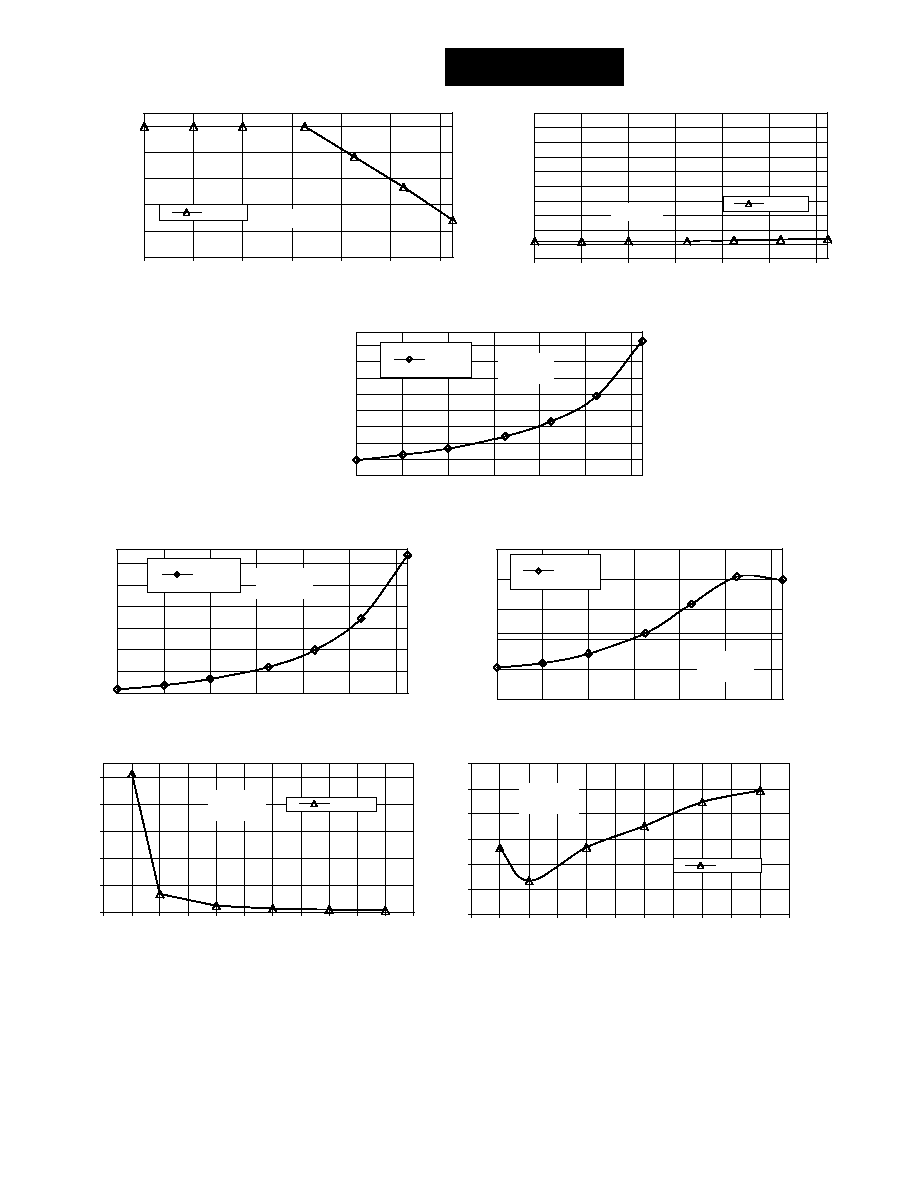
G2 Series/
2 F
ORM
A
A. Load Current vs. Ambient Temperature
B. Output MOSFET BV vs. Ambient Temperature
C. On-Resistance vs. Ambient Temperature
D. On Time vs. Ambient Temperature
E. Turn Off Time vs. Ambient Temperature
F. Turn On Time vs. LED Forward Current
G. Turn Off Time vs. LED Forward Current
Temperature (Deg C)
Temperature (Deg C)
Temperature (Deg C)
Temperature (Deg C)
Temperature (Deg C)
LED Forward Current (mA)
LED Forward Current (mA)
Page 2 of 2
For recommended applications and more information contact:
USA: Sales Support (877) 502-5500 Tech Support (877) 702-7700 FAX (619) 710-8540
Crydom Corp, 2320 Paseo de las Americas, Ste. 201, San Diego, CA 92154
Email: sales@crydom.com WEB SITE: http://www.crydom.com
UK: +44 (0)1202 365070 ∑ FAX +44 (0)1202 365090 Crydom International Ltd., 7 Cobham
Road, Ferndown Industrial Estate, Ferndown, Dorset BH21 7PE, Email: intsales@crydom.com.
GERMANY: +49 (0)180 3000 506