Series IAC, (S)MIAC, X4IAC
AC Input Modules
INPUT SPECIFICATIONS
IAC5
IAC15
IAC24
IAC5A
IAC15A
IAC24A
(S)MIAC 5
(S)MIAC 15
(S)MIAC 24
(S)MIAC 5A
(S)MIAC 15A
(S)MIAC 24A
X4IAC5
X4IAC15
X4IAC24
X4IAC5A
X4IAC15A
X4IAC24A
Nominal input voltage [Vrms/Vdc]
120
120
120
240
240
240
Minimum Input Voltage [Vrms/Vdc]
90
90
90
180
180
180
Maximum Input Voltage [Vrms/Vdc]
140
140
140
280
280
280
Maximum Input Current [mA rms]
10
10
10
8
8
8
Drop Out Current [mA rms]
2.5
2.5
2.5
1.5
1.5
1.5
Allowable Off-state Current [mA rms]
3.0
3.0
3.0
2.0
2.0
2.0
Allowable Off-state Voltage [Vrms/Vdc]
50.0
50.0
50.0
120
120
120
OUTPUT SPECIFICATIONS
Nominal Logic Voltage [Vdc]
5
15
24
5
15
24
Minimum Logic Voltage [Vdc] (X4 Series)
1.5 (3)
8.5 (10)
16.5 (18)
1.5 (3)
8.5 (10)
16.5 (18)
Maximum Logic Voltage [Vdc] (X4 Series)
6.0 (7)
18.5 (20)
30.5 (32)
6.0 (7)
18.5 (20)
30.5 (32)
Typical Logic Supply Current [mAdc]
10
10
10
10
10
10
Max. Logic Supply Current [mAdc]
18.5
16
14
18.5
16
14
Max. Logic Sup. Leak. Current [µAdc]
10
10
10
10
10
10
Maximum Output Voltage [Vdc]
30
30
30
30
30
30
Maximum Output Current [mAdc]
50
50
50
50
50
50
Max. Output Leakage Current [µAdc]
10
10
10
10
10
10
Max. Output Voltage Drop [mVdc]
200 200
200
200
200
200
Maximum Turn-on Time [msec]
20
20
20
20
20
20
Maximum Turn-off Time [msec]
30
30
30
30
30
30
Solid state I/O switching modules deliv-
er an electrically clean, photo-isolated,
noise-free "output" interface from
logic level control systems to external
loads such as motors, valves, solenoids,
etc. -- or an "input" interface from the
load or sensors to microprocessor or
computer-based logic level systems.
Designed for long, reliable service in
demanding industrial environments.
∑ Statu s Indicating LED on
X4 Series
∑ UL, CSA, and CE
FastFax Document No. 302
SERIES IDC.
Rev. 031902
PAGE 1 OF 2
© 2002 CRYDOM CORP Specifications subject to change without notice.
For recommended applications and more information contact:
USA: Sales Support (877) 502-5500 Tech Support (877) 702-7700 FAX (619) 710-8540
Crydom Corp, 2320 Paseo de las Americas, Ste. 201, San Diego, CA 92154
Email: sales@crydom.com WEB SITE: http://www.crydom.com
UK: +44 (0)1202 365070 ∑ FAX +44 (0)1202 365090 Crydom International Ltd., 7 Cobham
Road, Ferndown Industrial Estate, Ferndown, Dorset BH21 7PE, Email: intsales@crydom.com.
GERMANY: +49 (0)180 3000 506
Series IAC, (S)MIAC, X4IAC
AC Input Modules
GENERAL SPECIFICATIONS
Operating temperatue ranger
–30 to +80∞C
Storage temperature range
–40 to +100∞C
Isolation
4,000 V rms
Capacitance input to output
8 pF
Line frequency range
47 to 63 Hz
Package Color
Yellow
FastFax Document No. 302
SERIES IDC.
Rev. 031902
PAGE 2 OF 2
© 2002 CRYDOM CORP Specifications subject to change without notice.
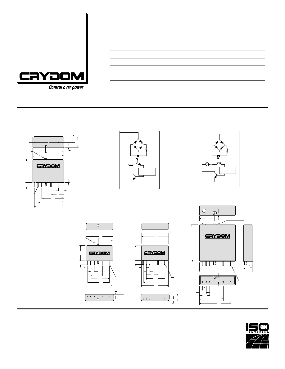
W IRING & M ECHANICAL DIAGRAMS
All dimensions are in inches (millimeters)
1.25
(31.7)
.25
(6.3)
.040 (1.0) DIA.
(5 PLACES)
.70
(17.8)
1.20
(30.5)
1.40
(35.5)
1.60
(40.6)
1.70
(43.1)
.30
(7.6)
.100
(2.5)
.30
(7.6)
.60
(15.2)
1.00
(25.4)
.030
(0.8)
CAPTIVE
#4-40. PHILLIPS
HEAD HOLD
DOWN SCREW
1
2
3
4
5
BOTTOM VIEW
X4 Series, X4IAC
Standard Series, IAC
1.78
(45.2)
0.35
(8.9)
1.82
(46.2)
1.70
(43.1)
1.3
(33.0)
0.81
(20.6)
0.55
(13.9)
0.20
(5.1)
0.48
(12.2)
0.20
(5.1)
CAPTIVE
#4-40. PHILLIPS
HEAD HOLD
DOWN SCREW
0.15
(3.8)
.040 (1.0) DIA.
(5 PLACES)
LOGIC
GND
Vac/dc
OUT
1
2
3
4
5
+
-
Schmitt
Trigger
LOGIC
GND
Vac/dc
OUT
1
2
3
4
5
+
-
Schmitt
Trigger
Standard and Mi ni Pack
X4 Series
1.00
(25.4)
.25
(6.35)
.040 (1.0) DIA.
(5 PLACES)
.30
(7.6)
.200
(5.1)
.700
(17.8)
1.100
(27.9)
1.30
(43.1)
.100
(2.5)
.40
(10.2)
1
2
3+
5
BOTTOM VIEW
1.70
(43.1)
4
1.70
(43.1)
1.00
(25.4)
CAPTIVE
#4-40. PHILLIPS
HEAD HOLD
DOWN SCREW
MI NI-PACK Series, (S)MIAC
1.00
(25.4)
.25
(6.35)
.040 (1.0) DIA.
(5 PLACES)
.30
(7.6)
.200
(5.1)
.700
(17.8)
1.100
(27.9)
1.30
(43.1)
.100
(2.5)
.40
(10.2)
1
2
3+
5
BOTTOM VIEW
1.70
(43.1)
4
1.70
(43.1)
SM Prefix
M Prefix
APPLICATION NOTES
• Do not install or remove modules
in live (electrically hot) circuits.
High voltage may be present.
• An externally located
commutating diode must be
installed across inductive loads
• I/O module boards also available
For recommended applications and more information contact:
USA: Sales Support (877) 502-5500 Tech Support (877) 702-7700 FAX (619) 710-8540
Crydom Corp, 2320 Paseo de las Americas, Ste. 201, San Diego, CA 92154
Email: sales@crydom.com WEB SITE: http://www.crydom.com
UK: +44 (0)1202 365070 ∑ FAX +44 (0)1202 365090 Crydom International Ltd., 7 Cobham
Road, Ferndown Industrial Estate, Ferndown, Dorset BH21 7PE, Email: intsales@crydom.com.
GERMANY: +49 (0)180 3000 506