
CYNTEC CO., LTD.
DOCUMENT : SR890000N
REVISION : A1
PAGE : 1 OF 11
2W 7520 LOW RESISTNACE CHIP RESISTOR
1. Scope
This specification applies to 7.5mm x 2.0mm size 2W, fixed metal film low resistance value chip
resistors rectangular type.
2. Type Designation
RL7520W ≠ ≠
N
(1) (2)
(3)
(4)
(5)
Where
(1) Type and size
(2) Temperature coefficient of resistanceT.C.R.
(3) Nominal Resistance value:
Four digits of number
Refer to paragraph 4-1
The" R "shall be used as a decimal point.
(4)
Resistance
tolerance:
Refer to paragraph 4-1
(5) N = Sn plating (Lead free , RoHS compliant)
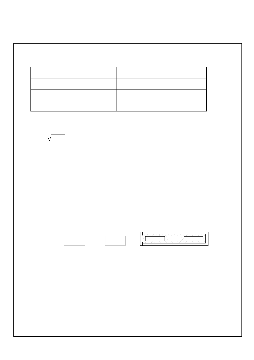
3. Construction and Physical Dimensions
Figure 1. Construction and Dimensions
W
d
t
L
a
a
Dimensions (mm)
Code
Letter
7520
L
2.0
± 0.2
W
7.5
± 0.3
t
0.8
± 0.2
a
0.40
± 0.2
d
0.40
± 0.2
Resistive element : Metal film
(Under protection film)
Electrode : Solder Sn (on Cu)
Protection film : Epoxy resin
Substrate : Alumina
CYNTEC CO., LTD.
DOCUMENT : SR890000N
REVISION : A1
PAGE : 2 OF 11
4. Ratings
4-1 Nominal Resistance Value and Temperature Coefficient of Resistance
Power Rating*
2 W
Resistance Value
0.001
~ 0.005
Resistance Tolerance
± 1%(F) , ± 2%(G) , ± 5%(J)
Temperature Coefficient of Resistance
±
100ppm/
4-2 Rated Voltage
The rated voltage shall be determined by the following expression.
R
P
V
◊
=
Where VRated voltage (V)
RNominal resistance value (
)
PRated dissipation (W)
4-3 Operating and Storage Temperature Range
-55 to +125
5. Marking
Resistance value mark on a top surface use four or three digits by JIS.
White bars are Cyntec internal use only.
Example
0.001
R001
0.002
R002
R001

CYNTEC CO., LTD.
DOCUMENT : SR890000N
REVISION : A1
PAGE : 3 OF 11
6. Characteristics
6-1 Electrical
6-1-1 Resistance
Resistance value shall be within the tolerance specified in paragraph 4-1
Refer to JIS C 5202 5.1
6-1-2 Temperature Coefficient of Resistance
Not exceed the temperature coefficient of resistance specified
Room temperature Room temperature + 100
Refer to JIS C 5202 5.2
6-1-3 Insulation Resistance
(1) Between Electrode and Protection Film
100M
or over
(2) Between Electrode and Substrate
1,000M
or over
The resistor shall be cramped in the metal block and tested, as shown below.
Test voltage : 100V
DC
for 1 minute
Refer to JIS C 5202 5.6 Mounting condition G.
6-1-4 Voltage Proof
R0.002, Resistance Change :
± (0.5%)
R0.002, Resistance Change : ± (3.0%)
Without damage by flashover, fire or breakdown, etc.
The voltage : 100V
AC
(rms.) for 1 minute
Refer to JIS C 5202 5.7
Insulation Plate
Spring
Sample Electrode
Metal Block
Measurement Point B
Pressure Rod
(Metal)
Measurement Point A
Substrate
Over coat Film
(R=0.5 mm)
A
B
Voltage Supply
Substrate Side

CYNTEC CO., LTD.
DOCUMENT : SR890000N
REVISION : A1
PAGE : 4 OF 11
6-2 Mechanical
6-2-1 Terminal Strength
R0.002, Resistance Change :
± (0.5%)
R0.002, Resistance Change : ± (3.0%)
Without mechanical damage such as breaks.
Electrical characteristics shall be satisfied.
If there are electrodes on both surfaces, it shall satisfy the above specifications on whichever
surface it may be fixated on.
Bending width : 3 mm 30 seconds
Refer to JIS C 5202 6.1.4.
R0.5
L
1/2L
Unit : mm
Resistor
Pressure rod
6-2-2 Body Strength
R0.002, Resistance Change :
± (0.5%)
R0.002, Resistance Change : ± (3.0%)
Without mechanical damage such as breaks.
A load of 10N using a R0.5 pressure rod shall be applied to the center in the direction
of the arrow and held for 10 seconds.
Refer to JIS C 5202 6.2
20
45
Pre
ssure
Supports
45
Solder
Within ±2mm
Test PC Board
Sample
R230
Press Jig
Unit : mm
Refer to EIAJ RC-2530
A
m
pl
it
ude
3 mm
50

CYNTEC CO., LTD.
DOCUMENT : SR890000N
REVISION : A1
PAGE : 5 OF 11
6-2-3 Solderability
A new uniform coating of solder shall cover minimum of 95% of the surface
being immersed.
Temperature of solder : 245
± 5
Immersion duration : 2
± 0.5 seconds
Refer to JIS C 5202 6.5
6-2-4 Resistance to Soldering Heat
R0.002, Resistance Change :
± (0.5%)
R0.002, Resistance Change : ± (3.0%)
Electrical characteristics shall be satisfied.
Without distinct deformation in appearance.
(1) Solder bath method
Pre-heat : 100 to 110 30 seconds
Temperature : 270
± 5 10 ± 1seconds
(2) Reflow Soldering method
Peak temperature : 240
± 5 5 seconds
Temperature : 220
± 5 40 seconds
The heating apparatus shall be the upper-heated oven and temperature shall be
the board surface temperature.
(3) Soldering iron method
Bit temperature : 350
± 5 5 seconds
The resistor shall be stored at standard atmospheric conditions for 1 hour, after
which the measurements shall be made.
Refer to JIS C 5202 6.4
6-2-5 Resistance to Solvent
Without mechanical damage and distinct damage in appearance.
Immersion cleaning
At normal temperature 300 seconds in Isopropyl Alcohol.
Refer to JIS C 5202

CYNTEC CO., LTD.
DOCUMENT : SR890000N
REVISION : A1
PAGE : 6 OF 11
6-3 Endurance
6-3-1 Rapid Change of Temperature
R0.002, Resistance Change :
± (0.5%)
R0.002, Resistance Change : ± (3.0%)
Without distinct damage
Resistance shall be subjected to 5 cycles of the temperature cycle as following :
-55
± 2, 30 minutes
room temperature, 2 3 minutes
+125
± 2, 30 minutes
room temperature, 2 3 minutes
Refer to JIS C 5202 7.4
6-3-2 Dump Heat with Load
R0.002, Resistance Change :
± (0.5%)
R0.002, Resistance Change : ± (3.0%)
Without distinct damage
40
± 2 with relative humidity of 90 to 95% RH
DC rated voltage for 1.5 hours on 0.5 hours off
1,000 + 48 / - 0 hours
Refer to JIS C 5202 7.9
6-3-3 Endurance at 70
± 2
R0.002, Resistance Change :
± (1.0%)
R0.002, Resistance Change : ± (3.0%)
Without distinct damage
DC rated voltage for 1.5 hours on 0.5 hours off
1,000 + 48 / - 0 hours
Refer to JIS C 5202 7.10

CYNTEC CO., LTD.
DOCUMENT : SR890000N
REVISION : A1
PAGE : 7 OF 11
Mounting of the test sample onto the test board shall be either of following methods.
(1) Mounting by solder dipping
Epoxy based glue shall be applied in the middle of two lands of the test board. The resistor
shall be mounted in such a way that the electrodes of resistors will be evenly placed in the
land area and then adhesive resin shall be cured. After applying the Resin Flux with 25
weight % Methyl Alcohol, the board shall be soldered by dipping into a molten solder bath
with 260
± 5 for 3 to 5 seconds
(2) Mounting by reflow soldering
Solder paste with approximate 300m thickness shall be applied to the land of test board.
The resistor shall be mounted in such way that the electrodes of resistors will be evenly
placed in the land area and then shall be soldered under the circumstance that the surface
temperature of the board shall be raised 240 ±5(peak) for 3 to 5 seconds in an
upper-heater oven.
Test board A1, A2
Material : Glass Fabric Epoxy Resin
Board thickness : 1.6mm
Copper foil thickness : 0.035mm
Solder Resist Coating
(1) Test Board A1
100
40
Solder Resist
4
1.2
Unit : mm

CYNTEC CO., LTD.
DOCUMENT : SR890000N
REVISION : A1
PAGE : 8 OF 11
(2) Test Board A2
Test Board B
Material : Glass Fabric Epoxy Resin
Board thickness : 1.6mm
Copper foil thickness : 0.035mm
Solder Resist Coating
Solder Resist
Unit : mm
40
100
1.2
14
7.9
4
58.5
1.32
1.2
7.9
Unit : mm
Solder Resist
27
4

CYNTEC CO., LTD.
DOCUMENT : SR890000N
REVISION : A1
PAGE : 9 OF 11
7. Packaging
7-1 Dimensions
7-1-1 Tape packaging dimensions
A
2.6
±
0.2
D0
1.55
±
0.05
A0
2.3
±
0.1
K
1.4
±
0.1
B
8.2
±
0.2
T
0.3
±
0.05
B0
8.0
±
0.2
P0
4.0
±
0.1
E
1.75
±
0.1
P1
4.0
±
0.1
F
7.5
±
0.1
P2
2.0
±
0.2
W
16.0
±
0.3
Unit : mm
B
A0
A
P0
P2
W
B0
P1
D0
F
E
K
T
CYNTEC CO., LTD.
DOCUMENT : SR890000N
REVISION : A1
PAGE : 10 OF 11
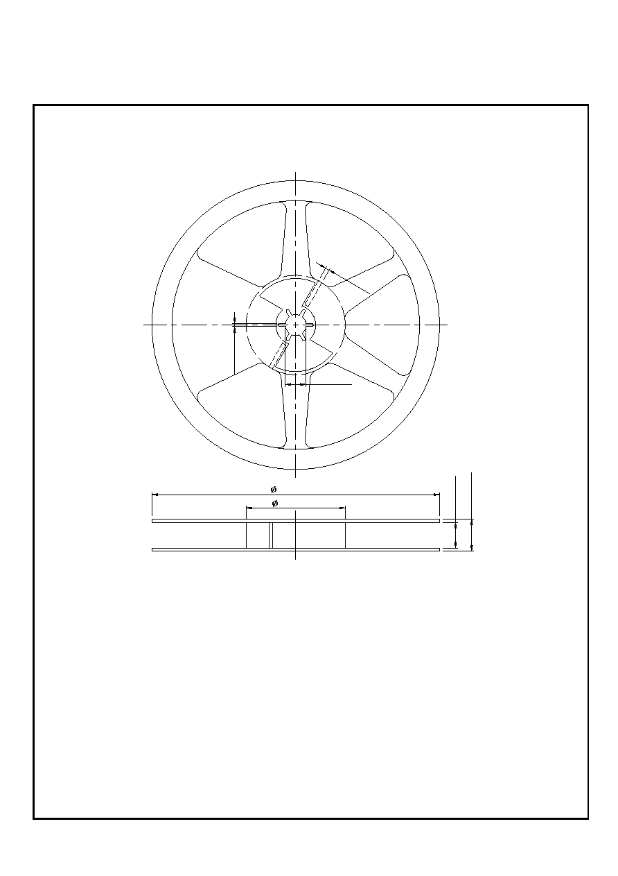
7-1-2 Reel Dimensions
13.0 ± 0.5
2.5 ±
0.5
2.0 ±
0
.
2
62.0 ± 0.5
180.0 ± 1.0
16
.4 ±
1
2
0
.
5 ±
0.
2

CYNTEC CO., LTD.
DOCUMENT : SR890000N
REVISION : A1
PAGE : 11 OF 11
7-2 Peel force of top cover tape
The peel speed shall be about 300 mm/min.
The peel force of top cover tape shall be between 0.1 to 0.7 N
7-3 Numbers of taping
2,000 pieces/reel
7-4 Making
The following items shall be marked on the reel.
(1) Type designation.
(2) Quantity
(3) Manufacturing date code
(4) Manufacturer's name
(5) The country of origin
165~180∞
Top Cover Tape
0.1N~0.7N