
CYNTEC CO., LTD.
DOCUMENT : RLN3C0000N
REVISION : A0
PAGE : 1 OF 9
1/10W 0816 LOW RESISTNACE CHIP RESISTOR
1. Scope
This specification applies to 0.8mm x 1.6mm size 1/10W, fixed metal film low resistance value chip
resistors rectangular type.
2. Type Designation
RLT 0816 - C - -
N
(1)
(2)
(3)
(4)
(5)
Where
(1) Size No.
(2) Power ranting :
C = 1/10W
(3) Resistance value: refer to paragraph 4-1
For example--
Four digits of number
R100 = 0.1
1R00 = 1.0
The "R" shall be used as a decimal point.
(4) Resistance tolerance: refer to paragraph 4-1.
(5) N = Sn plating ( Lead free , RoHS compliant)
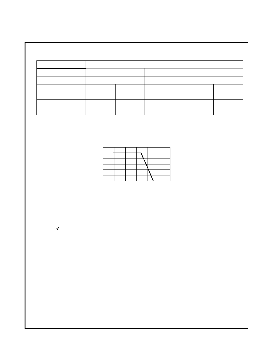
3. Outline Dimensions
Figure 1.
b
b
t
L
a
W
a
Dimension
Code
Letter
0816
L
1.60 ± 0.15
W
0.80 ± 0.15
t
0.45 ± 0.10
a
0.30 ± 0.20
b
0.30 ± 0.20
CYNTEC CO., LTD.
DOCUMENT : RLN3C0000N
REVISION : A0
PAGE : 2 OF 9
4. Ratings
4-1 Specification
Power Rating*
1/8 W
Resistance Values
E24 & E96 series
E24 series
Resistance Tolerance
±
1%(F)
±
2%(G) , ± 5%(J)
Resistance Range
0.2 ~
< 2.0
2.0 ~
< 10
0.1 ~
< 0.2
0.2 ~
< 2.0
2.0 ~
< 10
Temperature Coefficient
of Resistance ( ppm/)
±
250
±
100
±
350
±
250
±
100
Note*:
Power Rating is based on continuous full load operation at rated ambient temperature of 70.
For resistors operated at ambient temperature in excess of 70, the maximum load shall be
derated in accordance with the following curve.
Figure 2 Derating Curve
4-2 Rated Voltage
The rated voltage shall be determined by the following expression.
R
P
V
◊
=
Where VRated voltage (V)
RNominal resistance value ()
PRated dissipation (W)
4-3 Operating and Storage Temperature Range
-55 to +125
R
A
T
E
D
L
O
A
D
(
%
)
AMBIENT TEMPERATURE(
)
0
-55
70
125
100
CYNTEC CO., LTD.
DOCUMENT : RLN3C0000N
REVISION : A0
PAGE : 3 OF 9
5. Marking
Each resistor is marked with a 3-digit or 4-digits code on the protective coating to designate the
nominal resistance value.
5-1 0.1 R < 10 , Marking by 3 or 4 digits
Ex) E-24 0.47R 4 7 , 4.74 R 7 ,
E-96 4.994 R 9 9
5-2 R < 0.1 , Marking by 4 digits
Ex) E-24 0.075R 0 7 5
6. Characteristics
6-1 Electrical
6-1-1 Resistance
Resistance value shall be within the tolerance specified in paragraph 4-1
Refer to IEC 60115-1 Sub-clause 4.5.
6-1-2 Temperature Coefficient of Resistance
Not exceed the temperature coefficient of resistance specified in paragraph 4-1
Room temperature Room temperature + 100
Refer to IEC 60115-1 Sub-clause 4.13.
6-1-3 Short Time Overload
Resistance Change : ± (1.0%)
Without significant damage by flashover (spark ,arching),burning or breakdown etc.
Test voltage : 2.5 times the rated voltage.
Duration : 2 seconds
Refer to IEC 60115-1 Sub-clause 4.13.
CYNTEC CO., LTD.
DOCUMENT : RLN3C0000N
REVISION : A0
PAGE : 4 OF 9
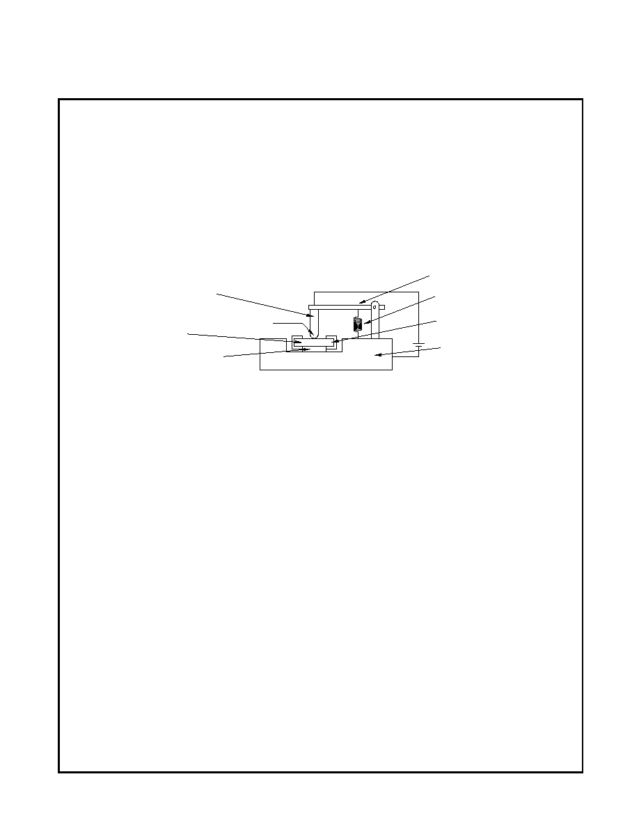
R0.5
Substrate
Protection Film
Pressure Rod
Measurement Point A
(Metal)
Test Sample
Spring
Insulation Prate
Metal Block
Measurement Point B
6-1-4 Insulation Resistance
(1) Between Electrode and Protection Film
100M or over
(2) Between Electrode and Substrate
1,000M or over
The resistor shall be cramped in the metal block and tested , as shown below.
Test voltage : 100V
DC
for 1 minute
Refer to IEC 60115-1 Sub-clause 4.6.
6-1-5 Voltage Proof
Resistance Change : ± (1.0%)
Without damage by flashover, fire or breakdown, as shown below.
The resistor shall be tested as shown in paragraph 4-1
The voltage : 100V
AC
(rms.) for 1 minute
Refer to IEC 60115-1 Sub-clause 4.7.
CYNTEC CO., LTD.
DOCUMENT : RLN3C0000N
REVISION : A0
PAGE : 5 OF 9
6-2 Mechanical
6-2-1 Terminal Strength
Resistance Change : ± (1.0%)
Without mechanical damage such as breaks.
Electrical characteristics shall be satisfied.
If there are electrodes on both surfaces, it shall satisfy the above specifications on whichever
surface may be fixated.
Bending Amplitude : 3 mm 30 seconds
Refer to IEC 60115-1 Sub-clause 4.33.
6-2-2 Body Strength
Resistance Change : ±(1.0%)
Without mechanical damage such as breaks.
A load of 10N using a R0.5 pressure rod shall be applied to the center in the direction of
the arrow and held for 10 seconds.
45
45
Solder
Supports
Within ± 2mm
Test PC Board
Sample
P
r
e
s
s
u
r
e
Press Jig
Refer to EIAJ RC-2530
Unit : mm
R230
A
m
p
l
i
t
u
d
e
3
m
m
20
50
R0.5
1/2L
L
Resistor
Pressure rod
Unit : mm