
PacketClockTM
One-PLL General Purpose Clock Generator
CY26404
Cypress Semiconductor Corporation
∑
3901 North First Street
∑
San Jose, CA 95134
∑
408-943-2600
Document #: 38-07470 Rev. **
Revised December 9, 2002
Features
Benefits
∑ Integrated phase-locked loop
Internal PLL with up to 400-MHz internal operation
∑ Low-skew, low-jitter, high-accuracy outputs
Meets critical timing requirements in complex system designs
∑ 3.3V operation with 2.5V output option
Enables application compatibility
∑ 16-TSSOP
Industry standard package saves on board space
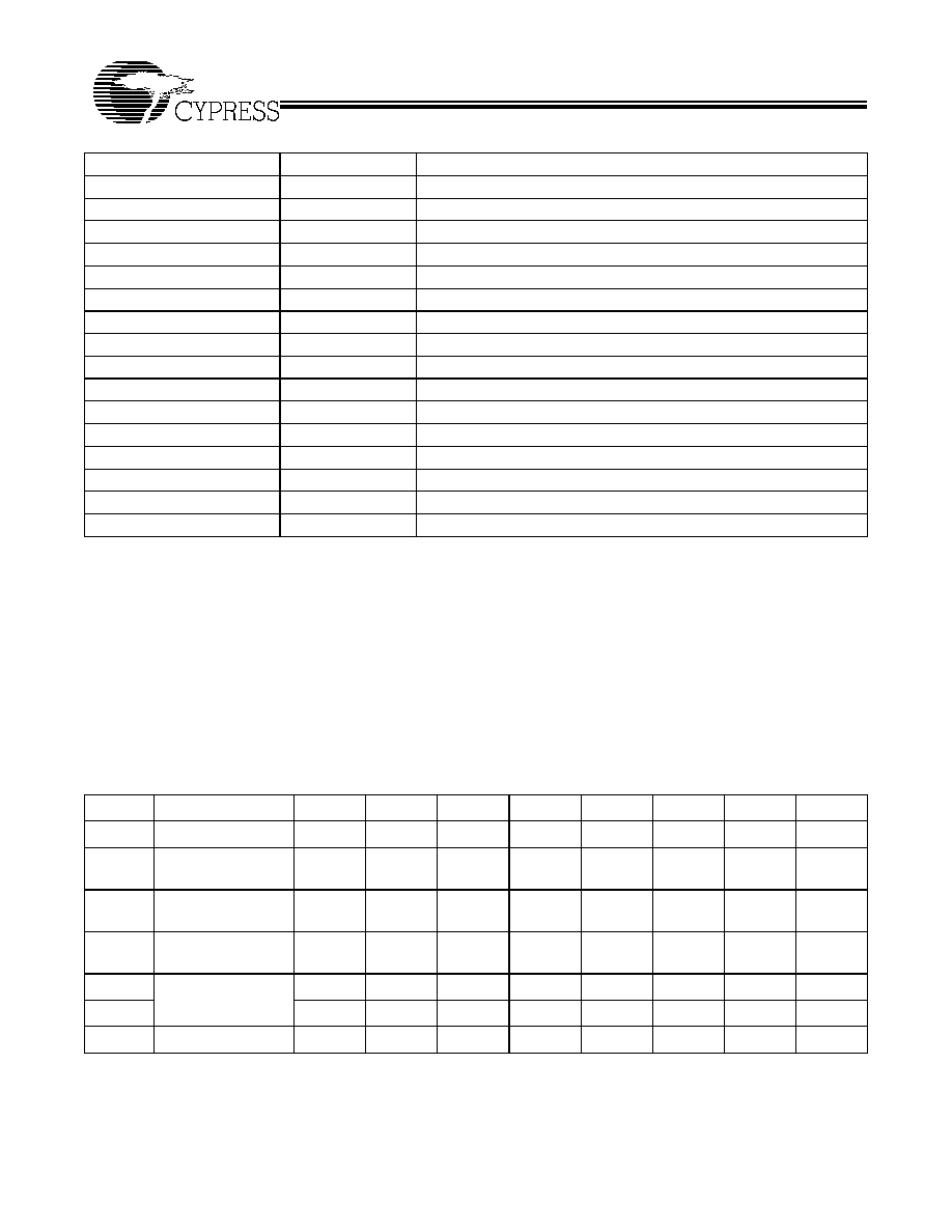
Part Number
Outputs
Input Frequency
Output Frequency Range
CY26404
6
20 MHz
2 x 50 MHz, 1 x 100 MHz
Output
Pin
Default Frequency
Unit
CLK1
7
50
MHz
CLK2
8
50
MHz
CLK3
9
OFF
CLK4
12
OFF
CLK5
14
100
MHz
CLK6
15
OFF
Logic Block Diagram
XIN
XOUT
CLK1 50 MHz
OUTPUT
MULTIPLEXER
AND
DIVIDERS
PLL
OSC.
CLK3 off
Q
P
VCO
VDDL
AVSS
AVDD
VSS
CLK2 50 MHz
VSSL
VDD
16-pin TSSOP
CY26404
1
2
3
4
5
6
7
8
9
10
11
12
13
14
15
16
VSS
VSSL
SCL
CLK1
XIN
XOUT
VDD
SDA
AVSS
CLK3
CLK2
CLK6
CLK5
AVDD
VDDL
CLK4
Pin Configuration
SCL
SDA
SPI
Control
CLK4 off
CLK5 100 MHz
CLK6 off
CY26404
Document #: 38-07470 Rev. **
Page 2 of 11
Frequency Calculations and Register
Definitions Using the Serial Programming
Interface (SPI)
The CY26404 provides an industry-standard serial interface
for volatile, in-system programming of unique frequencies and
options. Serial programming allows for quick design changes
and product enhancements, eliminates inventory of old design
parts, and simplifies manufacturing.
The SPI provides volatile programming, i.e., when the target
system is powered down, the CY26404 reverts back to its de-
fault state. When the system is powered back up, the SPI reg-
isters will need to be reconfigured again.
All programmable registers in the CY26404 are addressed
with eight bits and contain eight bits of data. The CY26404 is
a slave device with an address of 1101010 (6AH).
Table 1 lists the SPI registers and their definitions. Specific
register definitions and their allowable values are listed below.
Reference Frequency
The REF can be a crystal or a driven frequency. For crystals,
the frequency range must be between 8 MHz and 30 MHz. For
a driven frequency, the frequency range must be between
1 MHz and 133 MHz.
Using a Crystal as the Reference Input
The input crystal oscillator of the CY26404 is an important
feature because of the flexibility it allows the user in selecting
a crystal as a REF source. The input oscillator has program-
mable gain, allowing for maximum compatibility with a
reference crystal, regardless of manufacturer, process, perfor-
mance and quality.
Programmable Crystal Input Oscillator Gain Settings
The Input crystal oscillator gain (XDRV) is controlled by two
bits in register 12H, and are set according to Table 2. The
parameters controlling the gain are the crystal frequency, the
internal crystal parasitic resistance (ESR, available from the
manufacturer), and the CapLoad setting during crystal
start-up.
Bits 3 and 4 of register 12H control the input crystal oscillator
gain setting. Bit 4 is the MSB of the setting, and bit 3 is the
LSB. The setting is programmed according to Table 2.
All other bits in the register are reserved and should be pro-
grammed low. See Table 3 for bit locations and values.
Using an External Clock as the Reference Input
The CY26404 can also accept an external clock as reference,
with speeds up to 133 MHz. With an external clock, the XDRV
(register 12H) bits must be set according to Table 4.
Pin Description
Name
Pin Number
Description
XIN
1
Reference Input
VDD
2
Voltage Supply
AVDD
3
Analog Voltage Supply
SDA
4
Serial Data Input
AVSS
5
Analog Ground
VSSL
6
CLK1-CLK4 Ground
CLK 1
7
Clock Output 1 = 50 MHz at V
DDL
Level
CLK 2
8
Clock Output 2 = 50 MHz at V
DDL
Level
CLK 3
9
Default is Off
SCL
10
Serial Clock Input
VDDL
11
CLK1-CLK4 Voltage Supply (2.5V or 3.3V)
CLK 4
12
Default is Off
VSS
13
Ground
CLK 5
14
Clock Output 5 = 100 MHz at V
DD
Level
CLK 6
15
Default is Off
XOUT
[1]
16
Reference Output
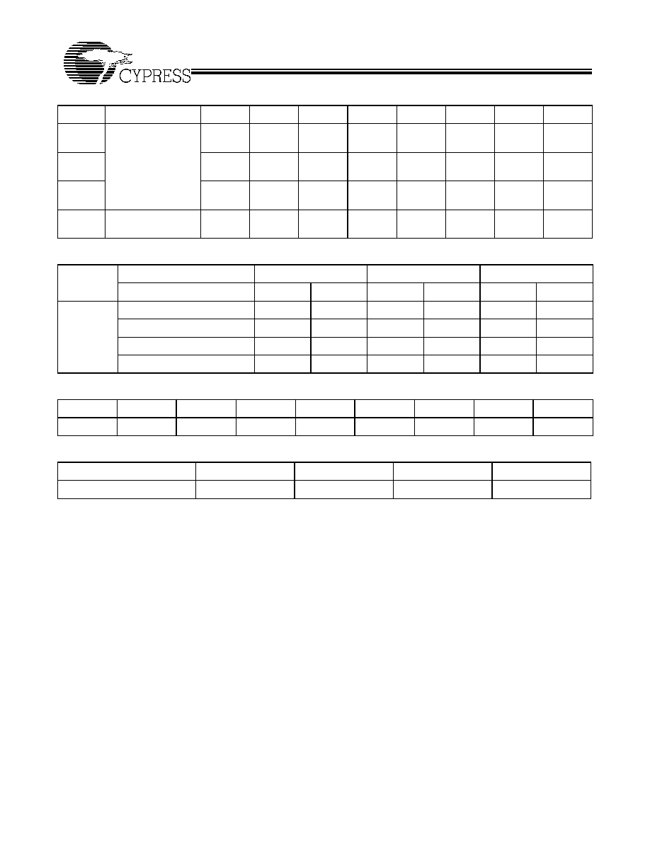
Table 1. Summary Table ≠ CY26404 Programmable Registers
Register
Description
D7
D6
D5
D4
D3
D2
D1
D0
09H
CLKOE control
0
0
CLK6
CLK5
CLK4
CLK3
CLK2
CLK1
0CH
DIV1SRC mux and
DIV1N divider
DIV1SRC DIV1N(6)
DIV1N(5)
DIV1N(4)
DIV1N(3)
DIV1N(2)
DIV1N(1)
DIV1N(0)
12H
Input crystal oscillator
drive control
0
0
0
XDRV(1)
XDRV(0)
0
0
0
13H
Input load capacitor
control
Cap-
Load(7)
Cap-
Load(6)
Cap-
Load(5)
Cap-
Load(4)
Cap-
Load(3)
Cap-
Load(2)
Cap-
Load(1)
Cap-
Load(0)
40H
Charge Pump and
PB counter
1
1
0
Pump(2)
Pump(1)
Pump(0)
PB(9)
PB(8)
41H
PB(7)
PB(6)
PB(5)
PB(4)
PB(3)
PB(2)
PB(1)
PB(0)
42H
PO counter, Q counter
PO
Q(6)
Q(5)
Q(4)
Q(3)
Q(2)
Q(1)
Q(0)
CY26404
Document #: 38-07470 Rev. **
Page 3 of 11
44H
Crosspoint switch
matrix control
CLKSRC2
for CLK1
CLKSRC1
for CLK1
CLKSRC0
for CLK1
CLKSRC2
for CLK2
CLKSRC1
for CLK2
CLKSRC0
for CLK2
CLKSRC2
for CLK3
CLKSRC1
for CLK3
45H
CLKSRC0
for CLK3
CLKSRC2
for CLK4
CLKSRC1
for CLK4
CLKSRC0
for CLK4
CLKSRC2
for CLK5
CLKSRC1
for CLK5
CLKSRC0
for CLK5
CLKSRC2
for CLK6
46H
CLKSRC1
for CLK6
CLKSRC0
for CLK6
1
1
1
1
1
1
47H
DIV2SRC mux and
DIV2N divider
DIV2SRC DIV2N(6)
DIV2N(5)
DIV2N(4)
DIV2N(3)
DIV2N(2)
DIV2N(1)
DIV2N(0)
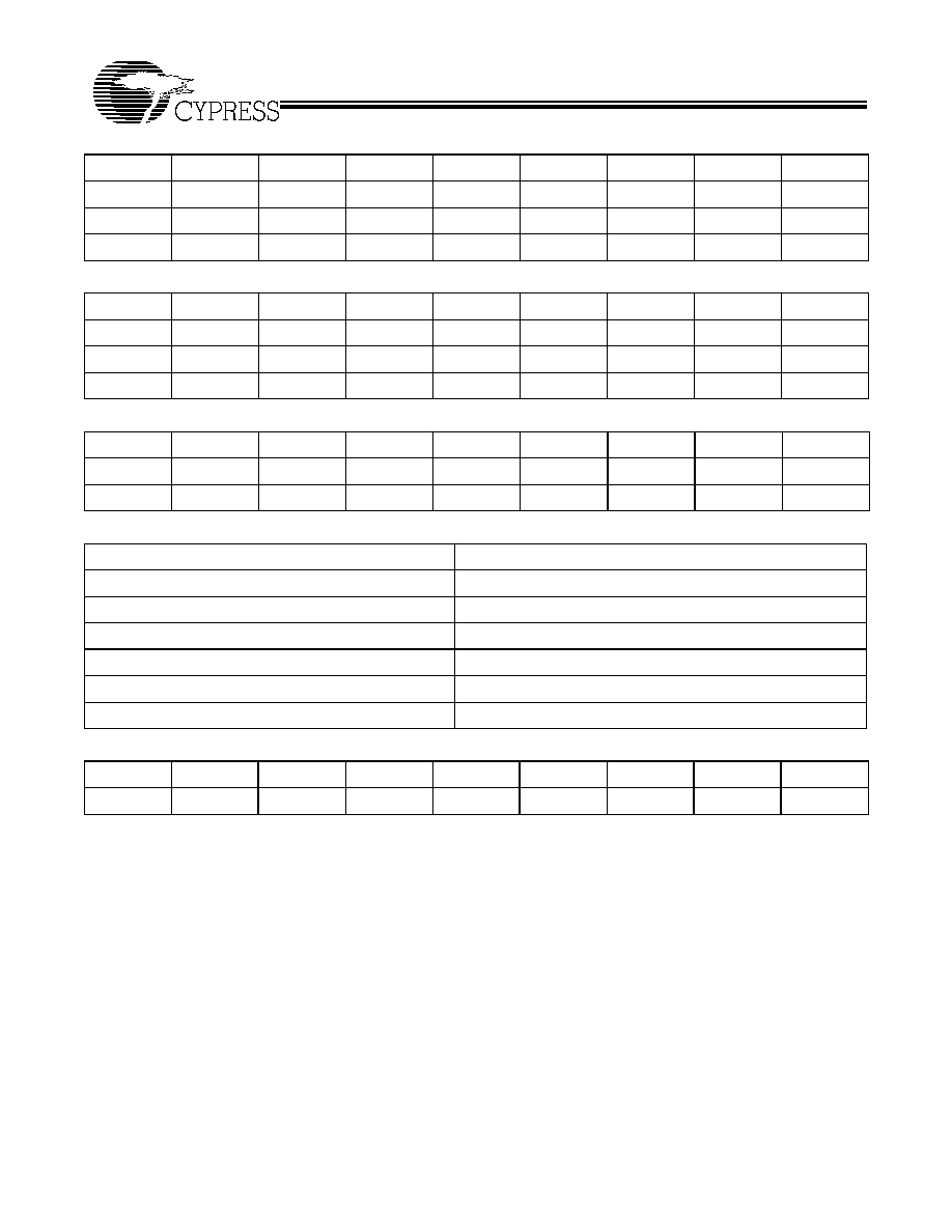
Table 2. Programmable Crystal Input Oscillator Gain Settings
Calculated CapLoad Value
00H 20H
20H≠30H
30H≠40H
Crystal ESR
30
60
30
60
30
60
Crystal
Input
Frequency
8≠15 MHz
00
01
01
10
01
10
15≠20 MHz
01
10
01
10
10
10
20≠25 MHz
01
10
10
10
10
11
25≠30 MHz
10
10
10
11
11
N/A
Table 3. Bit Locations and Values
Address
D7
D6
D5
D4
D3
D2
D1
D0
12H
0
0
0
XDRV(1)
XDRV(0)
0
0
0
Table 4. Programmable External Reference Input Oscillator Drive Settings
Reference Frequency
1≠25 MHz
25≠50 MHz
50≠90 MHz
90≠133 MHz
Drive Setting
00
01
10
11
Table 1. Summary Table ≠ CY26404 Programmable Registers (continued)
Register
Description
D7
D6
D5
D4
D3
D2
D1
D0

CY26404
Document #: 38-07470 Rev. **
Page 4 of 11
Input Load Capacitors
Input load capacitors allow the user to set the load capacitance
of the CY26404 to match the load capacitance from a crystal.
The value of the load capacitors is determined by 8 bits in a
programmable register [13H]. Total load capacitance is deter-
mined by the formula:
CapLoad = (C
L
≠ C
BRD
≠ C
CHIP
)/0.09375 pF
where:
∑ C
L
= specified load capacitance of your crystal.
∑ C
BRD
= the total board capacitance, due to external capac-
itors and board trace capacitance. In CyClocksRTTM, this
value defaults to 2 pF.
∑ C
CHIP
= 6 pF.
∑ 0.09375 pF = the step resolution available due to the 8-bit
register.
In CyclocksRT the CY26404 is matched to the CY22150, and
only the crystal capacitance (C
L
) is specified. C
CHIP
is set to 6
pF, and C
BRD
defaults to 2 pF. If your board capacitance is
higher or lower than 2 pF, the formula above can be used to
calculate a new CapLoad value and programmed into register
13H.
In CyClocksRT, enter the crystal capacitance (C
L
). The value
of CapLoad will be determined automatically and programmed
into the CY26404. Through the SDAT and SCLK pins, the
value can be adjusted up or down if your board capacitance is
greater or less than 2 pF. For an external clock source,
CapLoad defaults to 0. See Table 5 for CapLoad bit locations
and values.
The input load capacitors are placed on the CY26404 die to
reduce external component cost. These capacitors are true
parallel-plate capacitors, designed to reduce the frequency
shift that occurs when non-linear load capacitance is affected
by load, bias, supply and temperature changes.
PLL Frequency, Q Counter [42H(6..0)]
The first counter is known as the Q counter. The Q counter
divides REF by its calculated value. Q is a 7-bit divider with a
maximum value of 127 and minimum value of 0. The primary
value of Q is determined by 7 bits in register 42H (6..0), but 2
is added to this register value to achieve the total Q, or Q
total
.
Q
total
is defined by the formula:
Q
total
= Q + 2
The minimum value of Q
total
is 2. The maximum value of Q
total
is 129. Register 42H is defined in the table.
Stable operation of the CY26404 cannot be guaranteed if
REF/Q
total
falls below 250 kHz. Q
total
bit locations and values
are defined in Table 6.
PLL Frequency, P Counter [40H(1..0)], [41H(7..0)], [42H(7)
The next counter definition is the P (product) counter. The P
counter is multiplied with the (REF/Q
total
) value to achieve the
VCO frequency. The product counter, defined as P
total
, is
made up of two internal variables, PB and PO. The formula for
calculating P
total
is:
P
total
= (2(PB + 4) + PO)
PB is a 10-bit variable, defined by registers 40H(1:0) and
41H(7:0). The 2 LSBs of register 40H are the two MSBs of
variable PB. Bits 4..2 of register 40H are used to determine the
charge pump settings (see Section 5). The 3 MSBs of register
40H are preset and reserved and cannot be changed.
PO is a single-bit variable, defined in register 42H(7). This
allows for odd numbers in P
total
.
The remaining 7 bits of 42H are used to define the Q counter,
as shown in Table 6.
The minimum value of P
total
is 8. The maximum value of P
total
is 2055. To achieve the minimum value of P
total
, PB and PO
should both be programmed to 0. To achieve the maximum
value of P
total
, PB should be programmed to 1023, and PO
should be programmed to 1.
Stable operation of the CY26404 cannot be guaranteed if the
value of (P
total
*(REF/Q
total
)) is above 400 MHz or below
100 MHz. Registers 40H, 41H and 42H are defined in Table 7.
PLL Post Divider Options [OCH(7..0)], [47H(7..0)]
The output of the VCO is routed through two independent
muxes, then to two divider banks to determine the final clock
output frequency. The mux determines if the clock signal
feeding into the divider banks is the calculated VCO frequency
or REF. There are two select muxes (DIV1SRC and DIV2SRC)
and two divider banks (Divider Bank 1 and Divider Bank 2)
used to determine this clock signal. The clock signal passing
through DIV1SRC and DIV2SRC is referred to as DIV1CLK
and DIV2CLK, respectively.
The divider banks have 4 unique divider options available: /2,
/3, /4, and /DIVxN. DIVxN is a variable that can be indepen-
dently programmed (DIV1N and DIV2N) for each of the 2
divider banks. The minimum value of DIVxN is 4. The
maximum value of DIVxN is 127. A value of DIVxN below 4 is
not guaranteed to work properly.
DIV1SRC is a single bit variable, controlled by register OCH.
The remaining 7 bits of register OCH determine the value of
post divider DIV1N.
DIV2SRC is a single-bit variable, controlled by register 47H.
The remaining 7 bits of register 47H determine the value of
post divider DIV2N.
Register OCH and 47H are defined in Table 8.
Charge Pump Settings [40H(2..0)]
The correct pump setting is important for PLL stability. Charge
pump settings are controlled by bits (4..2) of register 40H, and
are dependent on internal variable PB (see "PLL Frequency,
P Counter[40H(1..0)], [41H(7..0)], [42H(7)]"). Table 9 summa-
rizes the proper charge pump settings, based on P
total
.
See Table 10 for register 40H bit locations and values.
Table 5. Input Load Capacitor Register Bit Settings
Address
D7
D6
D5
D4
D3
D2
D1
D0
13H
CapLoad(7)
CapLoad(6)
CapLoad(5)
CapLoad(4)
CapLoad(3)
CapLoad(2)
CapLoad(1)
CapLoad(0)
CY26404
Document #: 38-07470 Rev. **
Page 5 of 11
Although using the above table will guarantee stability, it is
recommended to use the Print Preview function in
CyClocksRT to determine the correct charge pump settings for
optimal jitter performance.
PLL stability cannot be guaranteed for values below 16 and
above 1023. If values above 1023 are needed, use
CyClocksRT to determine the best charge pump setting.
Clock Output Settings: CLKSRC ≠ Clock Output Cross-
point Switch Matrix [44H(7..0)], [45H(7..0)], [46H(7..6)]
CLKOE ≠ Clock Output Enable Control [09H(5..0)]
Every clock output can be defined to come from one of seven
unique frequency sources. The CLKSRC(2..0) crosspoint
switch matrix defines which source is attached to each
individual clock output. CLKSRC(2..0) is set in Registers 44H,
45H, and 46H. The remainder of register 46H(5:0) must be
written with the values stated in the register table when writing
register values 46H(7:6).
In addition, each clock output has individual CLKOE control,
set by register 09H(5..0).
When DIV1N is divisible by 4, then CLKSRC(0,1,0) is
guaranteed to be rising edge phase-aligned with
CLKSRC(0,0,1). When DIV1N is 6, then CLKSRC(0,1,1) is
guaranteed to be rising edge phase-aligned with
CLKSRC(0,0,1).
When DIV2N is divisible by 4, then CLKSRC(1,0,1) is
guaranteed to be rising edge phase-aligned with
CLKSRC(1,0,0). When DIV2N is divisible by 8, then
CLKSRC(1,1,0) is guaranteed to be rising edge phase-aligned
with CLKSRC(1,0,0).
Each clock output has its own output enable, controlled by
register 09H(5..0). To enable an output, set the corresponding
CLKOE bit to 1. CLKOE settings are in Table 13.
The output swing of CLK1 through CLK4 is set by V
DDL
. The
output swing of CLK5 and CLK6 is set by V
DD
.
Table 6. Q Counter Register Definition
Address
D7
D6
D5
D4
D3
D2
D1
D0
42H
PO
Q(6)
Q(5)
Q(4)
Q(3)
Q(2)
Q(1)
Q(0)
41H
PB(7)
PB(6)
PB(5)
PB(4)
PB(3)
PB(2)
PB(1)
PB(0)
42H
PO
Q(6)
Q(5)
Q(4)
Q(3)
Q(2)
Q(1)
Q(0)
Table 7. P Counter Register Definition
Address
D7
D6
D5
D4
D3
D2
D1
D0
40H
1
1
0
Pump(2)
Pump(1)
Pump(0)
PB(9)
PB(8)
41H
PB(7)
PB(6)
PB(5)
PB(4)
PB(3)
PB(2)
PB(1)
PB(0)
42H
PO
Q(6)
Q(5)
Q(4)
Q(3)
Q(2)
Q(1)
Q(0)
Table 8. PLL Post Divider Options
Address
D7
D6
D5
D4
D3
D2
D1
D0
OCH
DIV1SRC
DIV1N(6)
DIV1N(5)
DIV1N(4)
DIV1N(3)
DIV1N(2)
DIV1N(1)
DIV1N(0)
47H
DIV2SRC
DIV2N(6)
DIV2N(5)
DIV2N(4)
DIV2N(3)
DIV2N(2)
DIV2N(1)
DIV2N(0)
Table 9. Charge Pump Settings
Charge Pump Setting ≠ Pump(2..0)
Calculated P
total
000
16 ≠ 44
001
45 ≠ 479
010
480 ≠ 639
011
640 ≠ 799
100
800 ≠ 1023
101, 110, 111
Do not use ≠ device will be unstable
Table 10. Register 40H Change Pump Bit Settings
Address
D7
D6
D5
D4
D3
D2
D1
D0
40H
1
1
0
Pump(2)
Pump(1)
Pump(0)
PB(9)
PB(8)