Clock Generator for ATI
RS480 Chipset
CY28RS480
Cypress Semiconductor Corporation
∑
3901 North First Street
∑
San Jose
,
CA 95134
∑
408-943-2600
Document #: 38-07638 Rev. *C
Revised February 21, 2005
Features
∑ Supports AMD
CPU
∑ 200-MHz differential CPU clock pairs
∑ 100-MHz differential SRC clocks
∑ 48-MHz USB clock
∑ 33-MHz PCI clock
∑ 66-MHz HyperTransport
clock
∑ I
2
C support with readback capabilities
∑ Ideal Lexmark Spread Spectrum profile for maximum
electromagnetic interference (EMI) reduction
∑ 3.3V power supply
∑ 56-pin SSOP and TSSOP packages
CPU
SRC
HTT66
PCI
REF
USB_48
x2
x8
x1
x1
x 3
x 1
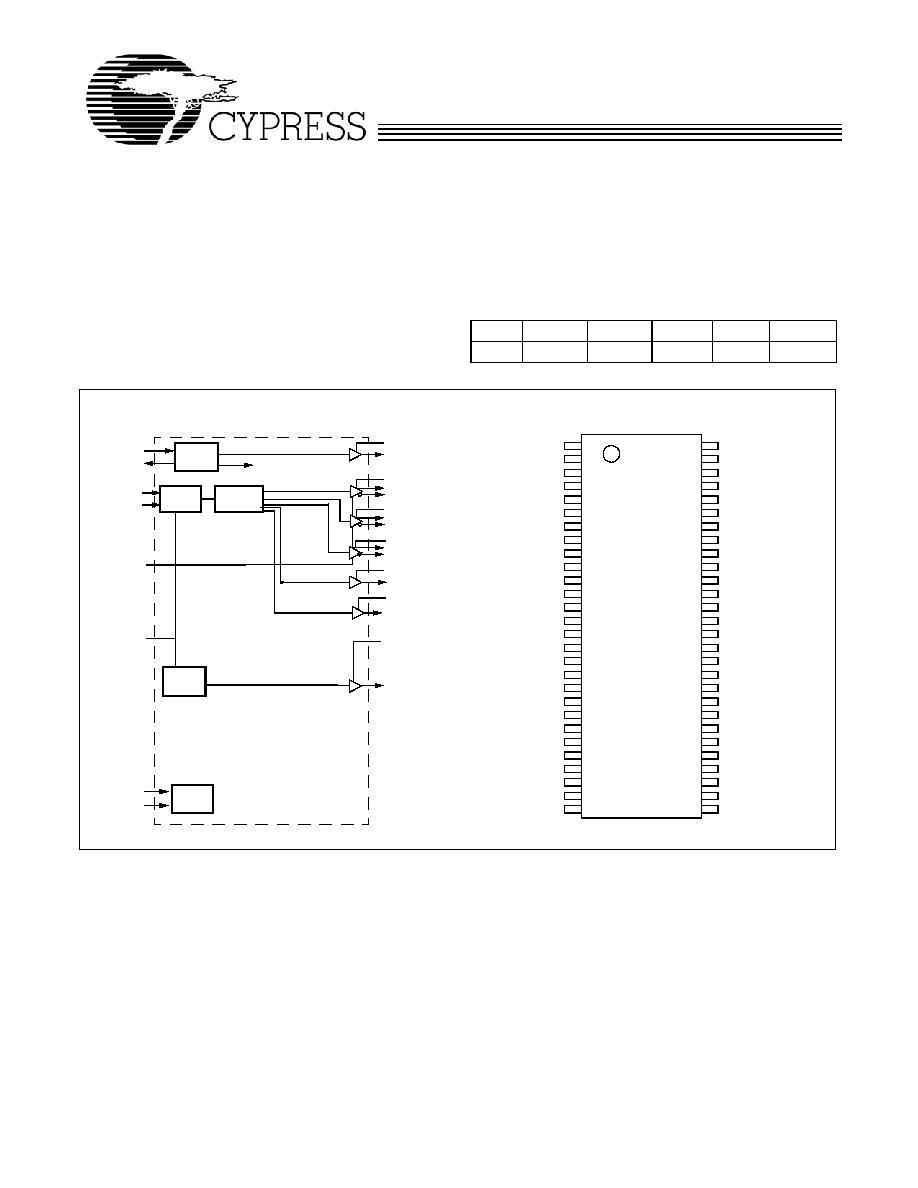
Block Diagram
Pin Configuration
XIN
XOUT
USB_48
VSS_48
NC
SCLK
SDATA
NC
CLKREQ#0
CLKREQ#1
SRCT5
SRCC5
VDD_SRC
VSS_SRC
SRCT4
SRCC4
SRCT3
SRCC3
VSS_SRC
VDD_SRC
SRCT2
SRCC2
SRCT1
SRCC1
VDD_REF
VSS_REF
SRCST0
VSS_SRC1
VSSA
IREF
VDDA
CPUT1
CPUC1
VSS_CPU
VDD_CPU
CPUT0
HTT66
VSS_HTT
VDD_HTT
PCI0
VDD_PCI
REF1
REF2
REF0
VDD_SRC1
VSS_SRC
SRCST1
SRCSC1
SRCT0
SRCC0
VSS_SRCS
SRCSC0
56
55
54
53
52
51
50
49
48
47
46
45
44
43
42
41
40
39
38
37
36
35
34
33
1
2
3
4
5
6
7
8
9
10
11
12
13
14
15
16
17
18
19
20
21
22
23
24
25
26
27
28
32
31
30
29
VDD_REF
XTAL
PLL Ref Freq
XOUT
XIN
OSC
SCLK
PLL1
I
2
C
Logic
VDD_48 MHz
SDATA
VDD_PCI
Divider
Network
VDD_CPU
REF[0:2]
IREF
PCI
PLL2
CPUT[0:1], CPUC[0:1],
VDD_SRC
SRCT[0:5],SRCC[0:5]
USB_48
CPU_STP#
CLKREQ[0:1]#
VDD_48
VDD_SRCS
VSS_PCI
C
Y
28RS48
0
56 SSOP/TSSOP
PD
VDD_SRCS
SRCST[0:1],SRCSC[0:1]
CPUC0
VDD_HTT
HTT66

CY28RS480
Document #: 38-07638 Rev. *C
Page 2 of 15
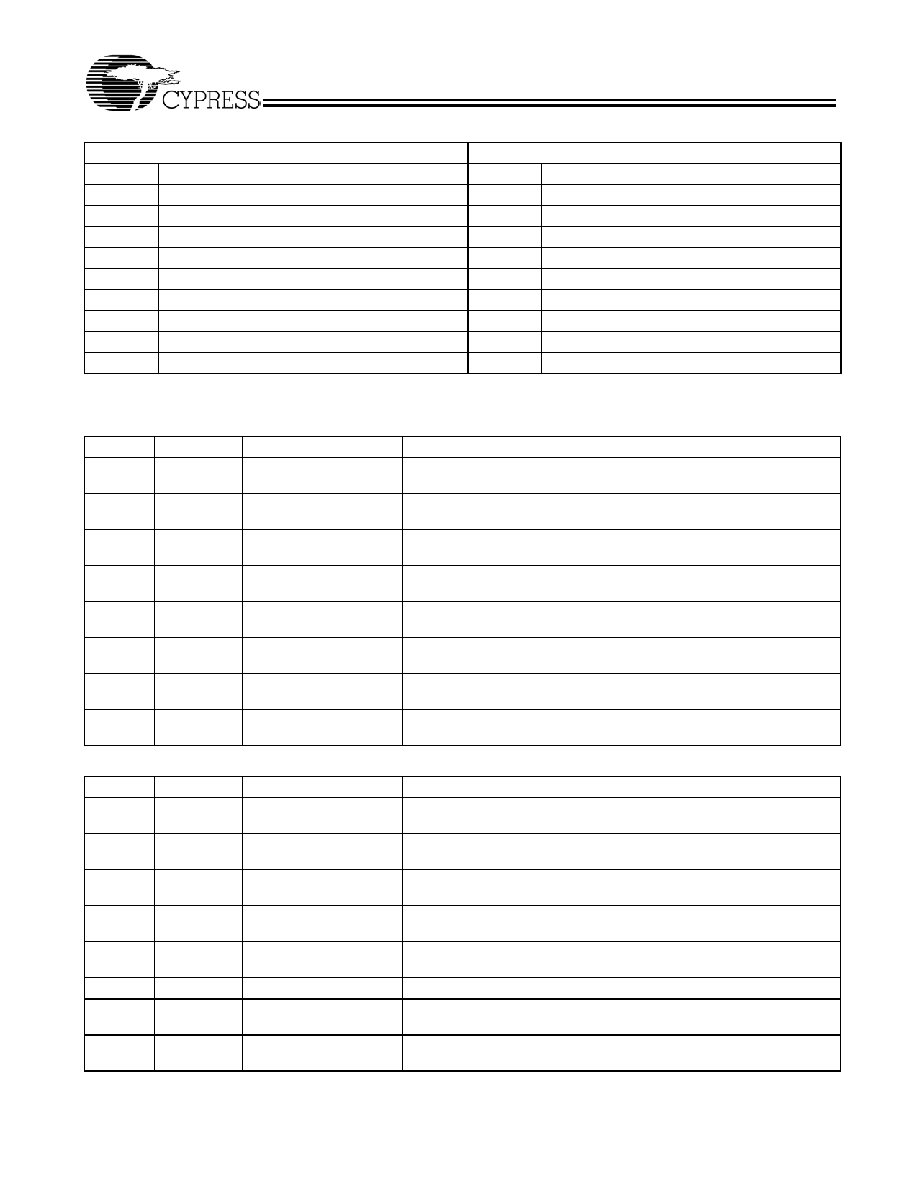
Pin Description
Pin No.
Name
Type
Description
41,40,45,44
CPUT/C
O, DIF Differential CPU clock outputs. AMD K8 buffer (200 Mhz).
50
PCI0
O
33-MHz clock output.
37
IREF
I
A precision resistor attached to this pin is connected to the internal current
reference.
52, 53, 54
REF[2:0]
O, SE 14.318-MHz REF clock output. Intel
Type-5 buffer.
7
SCLK
I,PU
SMBus-compatible SCLOCK.This pin has an internal pull-up, but is tri-stated in
power-down.
8
SDATA
I/O,PU SMBus-compatible SDATA.This pin has an internal pull-up, but is tri-stated in
power-down.
27, 28, 30, 29
SRCST/C[1:0]
O, DIF Differentials Selectable serial reference clock. Intel Type-X buffer.
Includes overclock support through SMBUS
12, 13, 16,
17, 18, 19,
22, 23, 24,
25, 34, 33
SRCT/C[5:0]
O, DIF 100-MHz differential serial reference clock. Intel Type-X buffer.
10,11
CLKREQ#[0:1]
I, SE,
PD
Output Enable control for SRCT/C. Output enable control required by Minicard
specification. This pin has an internal pull-down.
0 = Selected SRC outputs are enabled, 1 = Selected SRC outputs are disabled
4
USB_48
O, SE 48-MHz clock output. Intel Type-3A buffer.
47
HTT66
O, SE 66-MHz clock output. Intel Type-5 buffer.
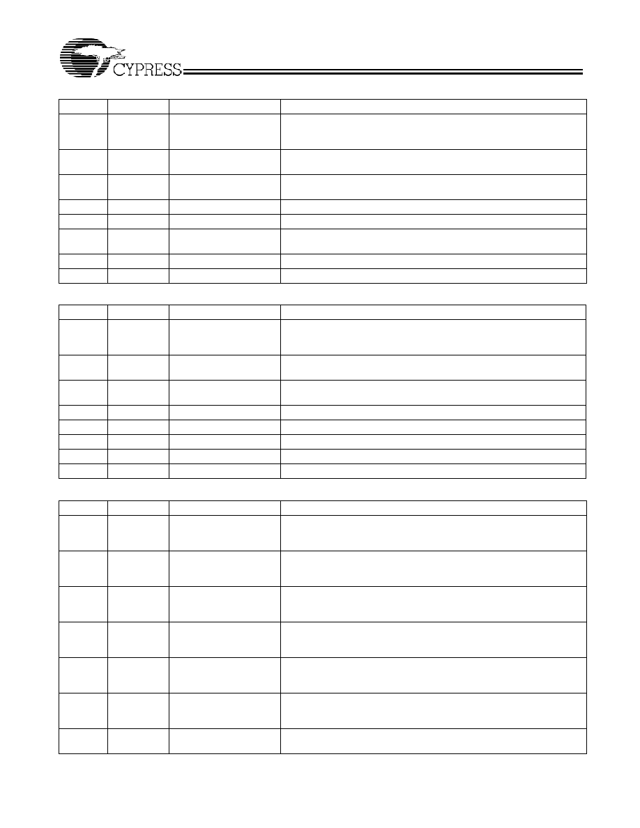
3
VDD_48
PWR 3.3V power supply for USB outputs
43
VDD_CPU
PWR 3.3V power supply for CPU outputs
51
VDD_PCI
PWR 3.3V power supply for PCI outputs
56
VDD_REF
PWR 3.3V power supply for REF outputs
48
VDD_HTT
PWR 3.3V power supply for Hyper Transport outputs
14, 21
VDD_SRC
PWR 3.3V power supply for SRC outputs
35
VDD_SRC1
PWR 3.3V power supply for SRC outputs
32
VDD_SRCS
PWR 3.3V power supply for SRCS outputs
39
VDDA
PWR 3.3V Analog Power for PLLs
5
VSS_48
GND Ground for USB outputs
42
VSS_CPU
GND Ground for CPU outputs
49
VSS_PCI
GND Ground for PCI outputs
55
VSS_REF
GND Ground for REF outputs
15, 20, 26
VSS_SRC
GND Ground for SRC outputs
36
VSS_SRC1
GND Ground for SRC outputs
31
VSS_SRCS
GND Ground
for SRCS outputs
46
VSS_HTT
GND Ground for HyperTransport outputs
38
VSSA
GND Analog Ground
1
XIN
I
14.318-MHz Crystal Input
2
XOUT
O
14.318-MHz Crystal Output
6, 9
NC
No Connects

CY28RS480
Document #: 38-07638 Rev. *C
Page 3 of 15
Serial Data Interface
To enhance the flexibility and function of the clock synthesizer,
a two-signal serial interface is provided. Through the Serial
Data Interface, various device functions, such as individual
clock output buffers, can be individually enabled or disabled.
The registers associated with the Serial Data Interface
initializes to their default setting upon power-up, and therefore
use of this interface is optional. Clock device register changes
are normally made upon system initialization, if any are
required. The interface cannot be used during system
operation for power management functions.
Data Protocol
The clock driver serial protocol accepts byte write, byte read,
block write, and block read operations from the controller. For
block write/read operation, the bytes must be accessed in
sequential order from lowest to highest byte (most significant
bit first) with the ability to stop after any complete byte has
been transferred. For byte write and byte read operations, the
system controller can access individually indexed bytes. The
offset of the indexed byte is encoded in the command code,
as described in Table 1.
The block write and block read protocol is outlined in Table 2
while Table 3 outlines the corresponding byte write and byte
read protocol. The slave receiver address is 11010010 (D2h).
Table 1. Command Code Definition
Bit
Description
7
0 = Block read or block write operation, 1 = Byte read or byte write operation
(6:5)
Chip select address, set to `00' to access device
(4:0)
Byte offset for byte read or byte write operation. For block read or block write operations, these bits should be '00000'
Table 2. Block Read and Block Write Protocol
Block Write Protocol
Block Read Protocol
Bit
Description
Bit
Description
1
Start
1
Start
8:2
Slave address ≠ 7 bits
8:2
Slave address ≠ 7 bits
9
Write 9
Write
10
Acknowledge from slave
10
Acknowledge from slave
18:11
Command Code ≠ 8 bits
18:11
Command Code ≠ 8 bits
19
Acknowledge from slave
19
Acknowledge from slave
27:20
Byte Count ≠ 8 bits
20
Repeat start
28
Acknowledge from slave
27:21
Slave address ≠ 7 bits
36:29
Data byte 1 ≠ 8 bits
28
Read = 1
37
Acknowledge from slave
29
Acknowledge from slave
45:38
Data byte 2 ≠ 8 bits
37:30
Byte Count from slave ≠ 8 bits
46
Acknowledge from slave
38
Acknowledge
....
Data Byte /Slave Acknowledges
46:39
Data byte 1 from slave ≠ 8 bits
....
Data Byte N ≠ 8 bits
47
Acknowledge
....
Acknowledge from slave
55:48
Data byte 2 from slave ≠ 8 bits
....
Stop
56
Acknowledge
....
Data bytes from slave / Acknowledge
....
Data Byte N from slave ≠ 8 bits
....
NOT Acknowledge
Table 3. Byte Read and Byte Write Protocol
Byte Write Protocol
Byte Read Protocol
Bit
Description
Bit
Description
1
Start
1
Start
8:2
Slave address ≠ 7 bits
8:2
Slave address ≠ 7 bits
9
Write
9
Write
10
Acknowledge from slave
10
Acknowledge from slave
CY28RS480
Document #: 38-07638 Rev. *C
Page 4 of 15
Control Registers
18:11
Command Code ≠ 8 bits
18:11
Command Code ≠ 8 bits
19
Acknowledge from slave
19
Acknowledge from slave
27:20
Data byte ≠ 8 bits
20
Repeated start
28
Acknowledge from slave
27:21
Slave address ≠ 7 bits
29
Stop
28
Read
29
Acknowledge from slave
37:30
Data from slave ≠ 8 bits
38
NOT Acknowledge
39
Stop
Table 3. Byte Read and Byte Write Protocol (continued)
Byte Write Protocol
Byte Read Protocol
Bit
Description
Bit
Description
Byte 0:Control Register 0
Bit
@Pup
Name
Description
7
1
SRC[T/C]5
SRC[T/C]5 Output Enable
0 = Disable (Hi-Z), 1 = Enable
6
1
SRC[T/C]4
SRC[T/C]4 Output Enable
0 = Disable (Hi-Z), 1 = Enable
5
1
SRC[T/C]3
SRC[T/C]3 Output Enable
0 = Disable (Hi-Z), 1 = Enable
4
1
SRC[T/C]2
SRC[T/C]2 Output Enable
0 = Disable (Hi-Z), 1 = Enable
3
1
SRC[T/C]1
SRC[T/C]1 Output Enable
0 = Disable (Hi-Z), 1 = Enable
2
1
SRC [T/C]0
SRC[T/C]0 Output Enable
0 = Disable (Hi-Z), 1 = Enable
1
1
SRCS[T/C]1
SRCS[T/C]1 Output Enable
0 = Disable (Hi-Z), 1 = Enable
0
1
SRCS[T/C]0
SRCS[T/C]0 Output Enable
0 = Disable (Hi-Z), 1 = Enable
Byte 1: Control Register 1
Bit
@Pup
Name
Description
7
1
REF2
REF2 Output Enable
0 = Disable, 1 = Enable
6
1
REF1
REF1 Output Enable
0 = Disable, 1 = Enable
5
1
REF0
REF0 Output Enable
0 = Disable, 1 = Enable
4
1
PCI0
PCI0 Output Enable
0 = Disable, 1 = Enable
3
1
USB_48
USB_48MHz Output Enable
0 = Disable, 1 = Enable
2
1
RESERVED
RESERVED
1
1
CPU[T/C]1
CPU[T/C]1 Output Enable
0 = Disable (Hi-Z), 1 = Enable
0
1
CPU[T/C]0
CPU[T/C]0 Output Enable
0 = Disable (Hi-Z), 1 = Enable
CY28RS480
Document #: 38-07638 Rev. *C
Page 5 of 15
Byte 2: Control Register 2
Bit
@Pup
Name
Description
7
1
CPUT/C
SRCT/C
Spread Spectrum Selection
`0' = ≠0.35%
`1' = ≠0.50%
6
1
USB_48
48-MHz Output Drive Strength
0 = 2x, 1 = 1x
5
1
PCI
33-MHz Output Drive Strength
0 = 2x, 1 = 1x
4
0
Reserved
Reserved
3
1
Reserved
Reserved
2
0
CPU
SRC
CPU/SRC Spread Spectrum Enable
0 = Spread off, 1 = Spread on
1
1
Reserved
Reserved
0
1
Reserved
Reserved
Byte 3: Control Register 3
Bit
@Pup
Name
Description
7
1
CLKREQ#
CLKREQ# drive mode
0 = SRC clocks driven when stopped, 1 = SRC clocks tri-state when
stopped
6
0
CPU
CPU pd drive mode
0 = CPU clocks driven when power-down, 1 = CPU clocks tri-state
5
1
SRC
SRC pd drive mode
0 = SRC clocks driven when power-down, 1 = SRC clocks tri-state
4
0
Reserved
Reserved
3
1
Reserved
Reserved
2
1
Reserved
Reserved
1
1
Reserved
Reserved
0
1
HTT66
HTT66 Output Drive Strength0 = High drive, 1 = Low drive.
Byte 4: Control Register 4
Bit
@Pup
Name
Description
7
0
SRC[T/C]5
SRC[T/C]5 CLKREQ0 control
1 = SRC[T/C]5 stoppable by CLKREQ#0 pin
0 = SRC[T/C]5 free running
6
0
SRC[T/C]4 SRC[T/C]4
CLKREQ#0
control
1 = SRC[T/C]4 stoppable by CLKREQ#0 pin
0 = SRC[T/C]4 free running
5
0
SRC[T/C]3 SRC[T/C]3
CLKREQ#0
control
1 = SRC[T/C]3 stoppable by CLKREQ#0 pin
0 = SRC[T/C]3 free running
4
0
SRC[T/C]2 SRC[T/C]2
CLKREQ#0
control
1 = SRC[T/C]2 stoppable by CLKREQ#0 pin
0 = SRC[T/C]2 free running
3
0
SRC[T/C]1 SRC[T/C]1
CLKREQ#0
control
1 = SRC[T/C]1 stoppable by CLKREQ#0 pin
0 = SRC[T/C]1 free running
2
0
SRC[T/C]0 SRC[T/C]0
CLKREQ#0
control
1 = SRC[T/C]1 stoppable by CLKREQ#0 pin
0 = SRC[T/C]1 free running
1
1
HTT66
HTT66 Output enable
0 = Disabled, 1 = Enabled