 | –≠–ª–µ–∫—Ç—Ä–æ–Ω–Ω—ã–π –∫–æ–º–ø–æ–Ω–µ–Ω—Ç: CY3120 | –°–∫–∞—á–∞—Ç—å:  PDF PDF  ZIP ZIP |

Warp
CPLD Development Software for PC
CY3120
Cypress Semiconductor Corporation
∑
3901 North First Street
∑
San Jose
,
CA 95134
∑
408-943-2600
Document #: 38-03049 Rev. *C
Revised August 18, 2002
Features
∑ VHDL (IEEE 1076 and 1164) and Verilog (IEEE 1364)
high-level language compilers with the following
features
-- Designs are portable across multiple devices
and/or EDA environments
-- Facilitates the use of industry-standard simulation
and synthesis tools for board and system-level
design
-- Support for functions and libraries facilitating
modular design methodology
∑ IEEE Standard 1076 and 1164 VHDL synthesis supports
-- Enumerated types
-- Operator overloading
-- For... Generate statements
-- Integers
∑ IEEE Standard 1364 Verilog synthesis supports
-- Reduction and conditional operators
-- Blocking and non-blocking procedural assignments
-- While loops
-- Integers
∑ Several design entry methods support high-level and
low-level design descriptions
-- Behavioral VHDL and Verilog (IF...THEN...ELSE;
CASE...)
-- Boolean
-- Aldec Active-HDLTM FSM graphical Finite State
Machine editor
-- Structural Verilog and VHDL
-- Designs can include multiple entry methods (but
only one HDL language) in a single design
∑ UltraGenTM Synthesis and Fitting Technology
-- Infers "modules" such as adders, comparators, etc.,
from behavioral descriptions and replaces them with
circuits pre-optimized for the target device
-- User selectable speed and/or area optimization on a
block-by-block basis
-- Perfect communication between synthesis and
fitting
-- Automatic selection of optimal flip-flop type
(D type/T type)
-- Automatic pin assignment
∑ Ability to specify timing constraints for all of the
Delta39K and PSI devices
∑ Supports all Cypress Programmable Logic Devices
-- PSITM (Programmable Serial Interface)
-- Delta39KTM Complex Programmable Logic Devices
(CPLDs)
-- Ultra37000TM CPLDs
-- F
LASH
370iTM CPLDs
-- MAX340TM CPLDs
-- Industry standard PLDs (16V8, 20V8, 22V10)
∑ VHDL and Verilog timing model output for use with
third-party simulators
∑ Timing simulation provided by Active-HDLTM Sim
Release 3.3 from Aldec
-- Graphical waveform simulator
-- Entry and modification of on-screen waveforms
-- Ability to probe internal nodes
-- Display of inputs, outputs, and high impedance (Z)
signals in different colors
-- Automatic clock and pulse creation
-- Support for buses
∑ Architecture Explorer and Dynamic Timing Analysis for
PSI and Delta39K devices
-- Graphical representation of exactly how your design
will be implemented on your specific target device
-- Zoom from the device level down to the macrocell
level
-- Determine the timing for any path and view that path
on a graphical representation of the chip
∑ Static Timing Report for all devices
∑ PC Support (Windows 98TM, Windows NTTM 4.0, and
Windows XPTM)
∑ On-line documentation and help
CY3120
Document #: 38-03049 Rev. *C
Page 2 of 8
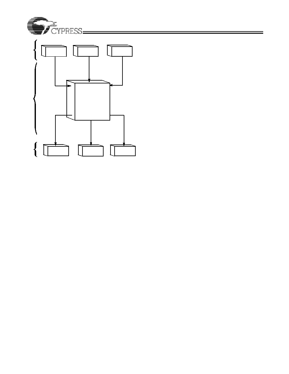
Functional Description
Warp
Æ
is a state-of-the-art HDL compiler for designing with
Cypress's CPLDs. Warp utilizes a subset of IEEE 1076/1164
VHDL and IEEE 1364 Verilog as its Hardware Description
Languages (HDL) for design entry. Then, it synthesizes and
optimizes the entered design, and outputs a JEDEC or Intel
Æ
hex file for the desired PLD or CPLD (see Figure 1).
Furthermore, Warp accepts VHDL or Verilog produced by the
Active-HDL FSM graphical Finite State Machine editor. For
simulation, Warp provides a timing simulator, as well as VHDL
and Verilog timing models for use with third party simulators.
VHDL and Verilog Compilers
VHDL and Verilog are powerful, industry standard languages
for behavioral design entry and simulation, and are supported
by all major vendors of EDA tools. They allow designers to
learn a single language that is useful for all facets of the design
process.
VHDL and Verilog offer designers the ability to describe
designs at many different levels. At the highest level, designs
can be entered as a description of their behavior. This behav-
ioral description is not tied to any specific target device. As a
result, simulation can be done very early in the design to verify
correct functionality, which significantly speeds the design
process.
The Warp syntax for VHDL and Verilog includes support for
intermediate level entry modes such as state tables and
Boolean entry. At the lowest level, designs can be described
using gate-level descriptions. Warp gives the designer the
flexibility to inter-mix all of these entry modes.
In addition, Verilog and VHDL allow you to design hierarchi-
cally, building up entities in terms of other entities. This allows
you to work either "top-down" (designing the highest levels of
the system and its interfaces first, then progressing to greater
and greater detail) or "bottom-up" (designing elementary
building blocks of the system, then combining these to build
larger and larger parts) with equal ease.
Because these languages are IEEE standards, multiple
vendors offer tools for design entry and simulation at both high
and low levels and synthesis of designs to different silicon
targets. The use of device-independent behavioral design
entry gives users the freedom to easily migrate to high volume
technologies. The wide availability of VHDL and Verilog tools
provides complete vendor independence as well. Designers
can begin their project using Warp for Cypress CPLDs and
convert to high volume ASICs using the same VHDL or
Verilog behavioral description with industry-standard
synthesis tools.
The VHDL and Verilog languages also allow users to define
their own functions. User-defined functions allow users to
extend the capabilities of the language and build reusable files
of tested routines. VHDL and Verilog provide control over the
timing of events or processes. They have constructs that
identify processes as either sequential, concurrent, or a
combination of both. This is essential when describing the
interaction of complex state machines.
VHDL and Verilog are rich programming languages. Their
flexibility reflects the nature of modern digital systems and
allows designers to create accurate models of digital designs.
Because they are not verbose languages they are easy to
learn and compile. In addition, models created in VHDL and
Verilog can readily be transported to other EDA Environments.
Warp supports IEEE 1076/1164 VHDL including loops,
for/generate statements, full hierarchical designs with
packages, enumerated types, and integers as well as IEEE
1364 Verilog including loops, reduction and conditional
operators.
A VHDL Design Example
Design Entry
Warp descriptions specify:
∑ The behavior or structure of a design.
∑ The mapping of signals in a design to the pins of
a PLD/CPLD (optional).
The part of a Warp description that specifies the behavior or
structure of the design is called an entity/architecture pair.
Entity/architecture pairs, as their name implies, are divided
into two parts: an entity declaration, which declares the
design's interface signals (i.e., defines what external signals
the design has, and what their directions and types are), and
a design architecture, which describes the design's behavior
or structure.
The entity portion of a design file is a declaration of what a
design presents to the outside world (the interface). For each
external signal, the entity declaration specifies a signal name,
a direction and a data type. In addition, the entity declaration
specifies a name by which the entity can be referenced in a
design architecture. This section shows code segments from
five sample design files. The top portion of each example
features the entity declaration.
Behavioral Description
The architecture portion of a design file specifies the function
of the design. As shown in Figure 1, multiple design-entry
methods are supported in Warp. A behavioral description
Figure 1. Warp VHDL Design Flow
DE
S
IGN
ENT
R
Y
COM
P
IL
A
T
ION
State Machine
VHDL
Programming
Timing
Simulator
VHDL, Verilog
&Third-Party
Simulation Models
VE
R
F
I
C
A
T
ION
UltraGen
TM
Synthesis
and
Fitting
Verilog
File

CY3120
Document #: 38-03049 Rev. *C
Page 3 of 8
in VHDL often includes well known constructs such as
If...Then...Else, and Case statements. Here is a code
segment from a simple state machine design (soda
vending machine) that uses behavioral VHDL to implement
the design:
LIBRARY ieee;
USE ieee.std_logic_1164.all;
ENTITY drink IS
PORT (nickel,dime,quarter,clock:#in
std_logic;
returnDime,returnNickel,giveDrink:out
std_logic);
END drink;
ARCHITECTURE fsm OF drink IS
TYPE drinkState IS (zero,five,ten,fifteen,
twenty,twentyfive,owedime);
SIGNAL drinkstatus:drinkState;
BEGIN
PROCESS BEGIN
WAIT UNTIL clock = '1';
giveDrink <= '0';
returnDime <= '0';
returnNickel <= '0';
CASE drinkStatus IS
WHEN zero =>
IF (nickel = '1') THEN
drinkStatus <= five;
ELSIF (dime = '1') THEN
drinkStatus <= Ten;
ELSIF (quarter = '1') THEN
drinkStatus <= twentyfive;
END IF;
WHEN five =>
IF (nickel = '1') THEN
drinkStatus <= ten;
ELSIF (dime = '1') THEN
drinkStatus <= fifteen;
ELSIF (quarter = '1') THEN
giveDrink <= '1';
drinkStatus <= zero
END IF;
-- Several states are omitted in this
-- example. The omitted states are ten,
-- fifteen, twenty, and twentyfive.
WHEN owedime =>
returnDime <= '1';
drinkStatus <= zero;
when others =>
-- This makes sure that the state
-- machine resets itself if
-- it somehow gets into an undefined state.
drinkStatus <= zero;
END CASE;
END PROCESS;
END FSM;
VHDL is a strongly typed language. It comes with several
predefined operators, such as + and /= (add, not-equal-to).
VHDL offers the capability of defining multiple meanings for
operators (such as +), which results in simplification of the
code written. For example, the following code segment shows
that "count <= count +1" can be written such that count is a
std_logic_vector, and 1 is an integer.
LIBRARY ieee;
USE ieee.std_logic_1164.all;
USE work.std_arith.all;
ENTITY sequence IS
port (clk: in std_logic;
s : inout std_logic);
end sequence;
ARCHITECTURE fsm OF sequence IS
SIGNAL count: std_logic_vector(3 downto 0);
BEGIN
PROCESS BEGIN
WAIT UNTIL clk = '1';
CASE count IS
WHEN x"0" | x"1" | x"2" | x"3" =>
s <= '1';
count <= count + 1;
WHEN x"4" | x"5" | x"6" | x"7" =>
s <= '0';
count <= count + 1;
WHEN x"8" | x"9" =>
s <= '1';
count <= count + 1;
WHEN others =>
s <= '0';
count <= (others => '0');
END CASE;
END PROCESS;
END FSM;
In this example, the + operator is overloaded to accept both
integer and std_logic arguments. Warp supports overloading
operators.
Functions
A major advantage of VHDL is the ability to implement
functions. The support of functions allows designs to be
reused by simply specifying a function and passing the appro-
priate parameters. Warp features some built-in functions
such as truth-table function (ttf). The ttf is particularly useful
for state machine or look-up table designs. The following
code describes a seven-segment display decoder imple-
mented with the ttf :
LIBRARY ieee;
USE ieee.std_logic_1164.all;
USE work.table_std.all;
CY3120
Document #: 38-03049 Rev. *C
Page 4 of 8
ENTITY seg7 IS
PORT(
inputs: IN STD_LOGIC_VECTOR (0 to 3)
outputs: OUT STD_LOGIC_VECTOR (0 to 6)
);
END SEG7;
ARCHITECTURE mixed OF seg7 IS
CONSTANT truthTable:
ttf_table (0 to 11, 0 to 10) := (
-- input&
output
-- -----------------------
"0000"&
"0111111",
"0001"&
"0000110",
"0010"&
"1011011",
"0011"&
"1001111",
"0100"&
"1100110",
"0101"&
"1101101",
"0110"&
"1111101",
"0111"&
"0000111",
"1000"&
"1111111",
"1001"&
"1101111",
"101-"&
"1111100", --creates E pattern
"111-"&
"1111100"
);
BEGIN
outputs <= ttf(truthTable,inputs);
END mixed;
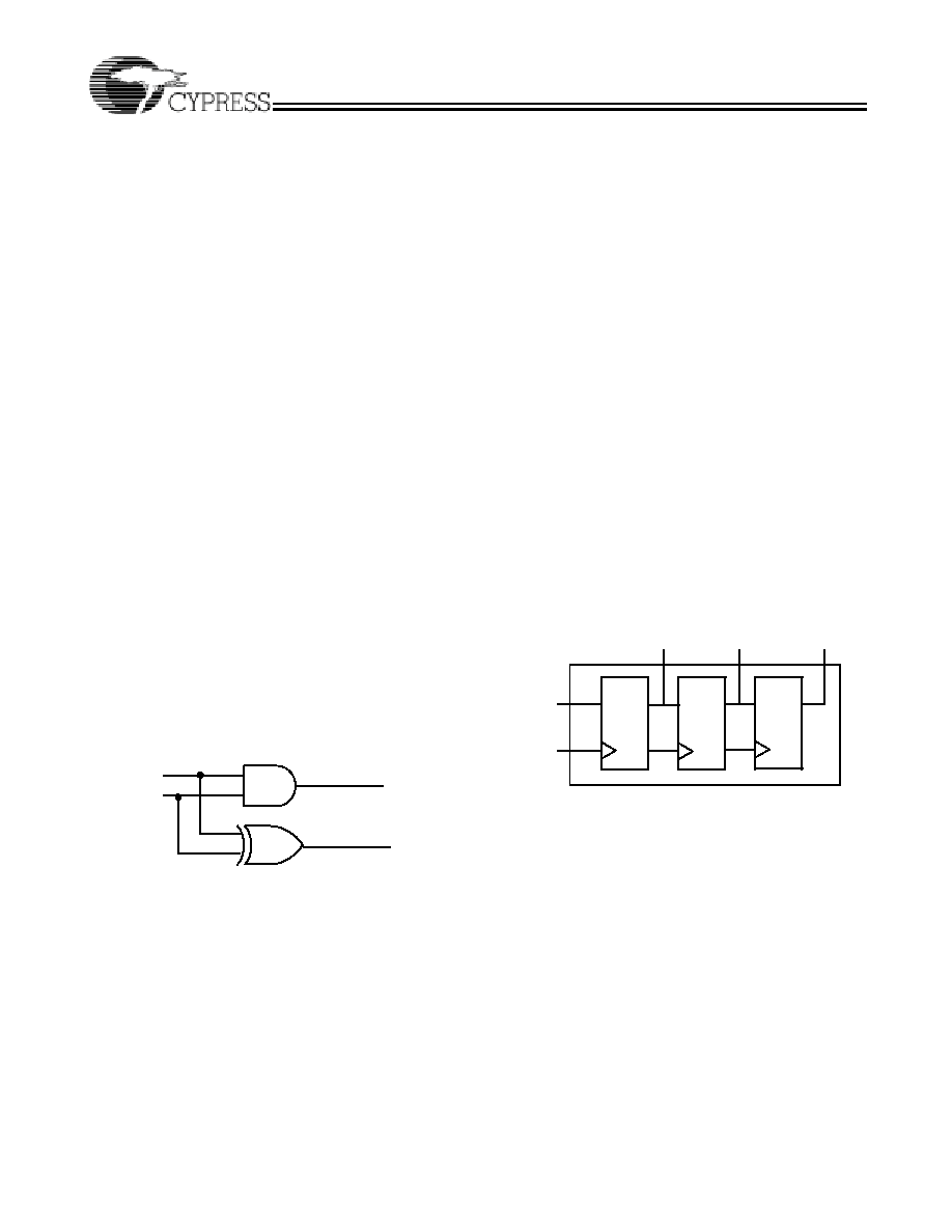
Boolean Equations
A third design-entry method available to Warp users is Boolean
equations. Figure 2 displays a schematic of a simple one-bit
half adder. The following code describes how this one-bit half
adder can be implemented in Warp with Boolean equations:
LIBRARY ieee;
USE ieee.std_logic_1164.all;
--entity declaration
ENTITY half_adder IS
PORT (x, y : IN std_logic;
sum, carry : OUT std_logic);
END half_adder;
--architecture body
ARCHITECTURE behave OF half_adder IS
BEGIN
sum <= x XOR y;
carry <= x AND y;
END behave;
Structural VHDL
While all of the design methodologies described thus far are
high-level entry methods, structural VHDL provides a method
for designing at a very low level. In structural descriptions, the
designer simply lists the components that make up the design
and specifies how the components are wired together.
Figure 3 displays the schematic of a simple three-bit shift
register and the following code shows how this design can be
described in Warp using structural VHDL:
LIBRARY ieee;
USE ieee.std_logic_1164.all;
USE work.rtlpkg.all;
ENTITY shifter3 IS port (
clk : IN STD_LOGIC;
x : IN STD_LOGIC;
q0 : OUT STD_LOGIC;
q1 : OUT STD_LOGIC;
q2 : OUT STD_LOGIC);
END shifter3;
ARCHITECTURE struct OF shifter3 IS
SIGNAL q0_temp, q1_temp, q2_temp : STD_LOGIC;
BEGIN
d1 : DFF PORT MAP(x,clk,q0_temp);
d2 : DFF PORT MAP(q0_temp,clk,q1_temp);
d3 : DFF PORT MAP(q1_temp,clk,q2_temp);
q0 <= q0_temp;
q1 <= q1_temp;
q2 <= q2_temp;
END struct;
All of the design-entry methods described can be mixed as
desired. VHDL has the ability to combine both high- and
low-level entry methods in a single file. The flexibility and
power of VHDL allows users of Warp to describe designs using
whatever method is appropriate for their particular design.
A Verilog Design Example
Design Entry
Warp descriptions specify:
∑ The behavior or structure of a design.
∑ The mapping of signals in a design to the pins of a
PLD/CPLD (optional).
The part of a Warp description that specifies the behavior or
structure of the design is called a module. The module
declares the design's interface signals (i.e., defines what
external signals the design has, and what their directions and
types are).
Figure 2. One-Bit Half Adder
x
y
carry
sum
1
Figure 3. Three-Bit Shift Register Circuit Design
clk
d
q
clk
d
q
clk
d
q
x
clk
q0
q1
q2
CY3120
Document #: 38-03049 Rev. *C
Page 5 of 8
The module portion of a design file is a declaration of what a
design presents to the outside world (the interface). For each
external signal, the module specifies a signal name, a direction
and a data type. In addition, the module declaration specifies
a name by which the entity can be referenced in other
modules. This section shows code segments from four sample
design files. The top portion of each example features the
module declaration.
Behavioral Description
The module portion of a design file specifies the function of the
design. As shown in Figure 1, multiple design-entry methods
are supported in Warp. A behavioral description in Verilog
often includes well known constructs such as If
...
Else, and
Case statements. Here is a code segment from a simple
state machine design (soda vending machine) that uses
behavioral Verilog to implement the design:
MODULE drink (nickel, dime, quarter, clock,
returnDime, returnNickel,
giveDrink);
INPUT nickel, dime, quarter, clock;
OUTPUT returnDime,returnNickel,giveDrink;
REG returnDime, returnNickel, giveDrink;
PARAMETER zero = 0, five = 1, ten = 2,
fifteen = 3, twenty = 4, twentyfive = 5
owedime = 6;
REG[1:0] drinkStatus;
ALWAYS@ (POSEDGE clock)
BEGIN
giveDrink = 0;
returnDime = 0;
returnNickel = 0;
CASE(drinkStatus)
zero: BEGIN
IF
(nickel)
drinkStatus = five;
ELSE IF (dime)
drinkStatus = ten;
ELSE IF (quarter)
drinkStatus = twentyfive;
END
five: BEGIN
IF
(nickel)
drinkStatus = ten;
ELSE IF (dime)
drinkStatus = fifteen;
ELSE IF (quarter)
BEGIN
drinkStatus = zero;
giveDrink = 1;
END
END
// Several states are omitted in this
// example. The omitted states are ten
// fifteen, twenty, and twentyfive.
owedime: BEGIN
returnDime = 1;
drinkStatus = zero;
END
default: BEGIN
// This makes sure that the state
// machine resets itself if
// it somehow gets into an undefined state.
drinkStatus = zero;
END
ENDCASE
END
ENDMODULE
Verilog is not a strongly typed language. The simplicity and
readability of the following code is increased by use of the
CASEX. The CASEX command accepts "Don't Cares" and
chooses the branch depending on the value of the expression.
MODULE sequence (clk, s);
INPUT clk;
INOUT s;
WIRE s;
REG temp;
REG[3:0] count;
ALWAYS@(POSEDGE clk)
CASEX(count)
4'b00XX: BEGIN
temp=1;
count=count+1;
end
4'b01XX: BEGIN
temp=0;
count=count+1;
end
4'b100X: BEGIN
temp=1;
count=count+1;
end
default: BEGIN
temp=0;
count=0;
end
ENDCASE
ASSIGN s=temp;
ENDMODULE
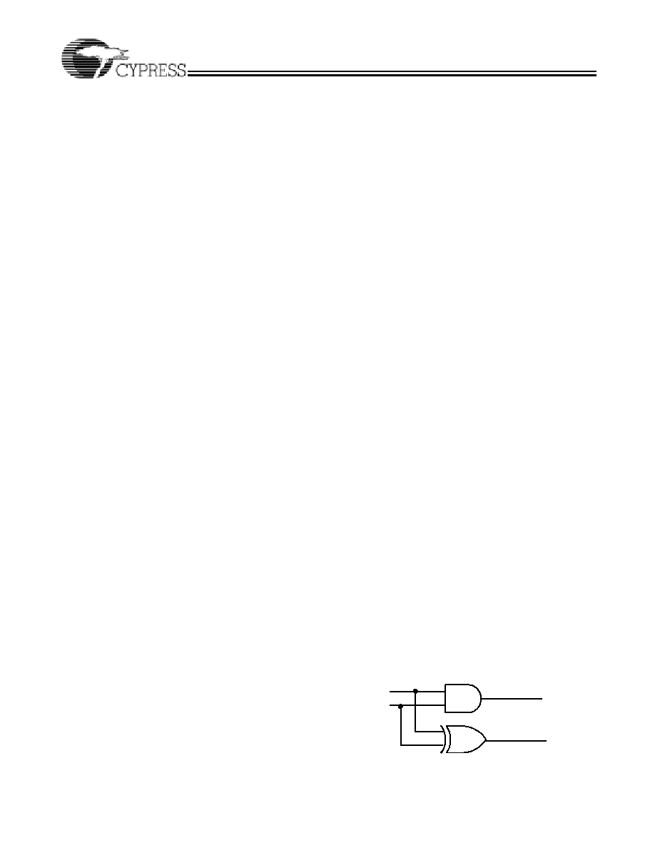
Boolean Equations
A second design-entry method available to Warp Verilog users
is Boolean equations. Figure 4 displays a schematic of a
simple one-bit half adder. The following code describes how
this one-bit half adder can be implemented in Warp with
Boolean equations:
Figure 4. One-Bit Half Adder
x
y
Carry
Sum