 | –≠–ª–µ–∫—Ç—Ä–æ–Ω–Ω—ã–π –∫–æ–º–ø–æ–Ω–µ–Ω—Ç: CY3650 | –°–∫–∞—á–∞—Ç—å:  PDF PDF  ZIP ZIP |
PRELIMINARY
USB Developer's Kit
CY3650
Cypress Semiconductor Corporation
∑
3901 North First Street
∑
San Jose
∑
CA 95134
∑
408-943-2600
Document #: 38-08003 Rev. **
Revised September 21, 2001
0
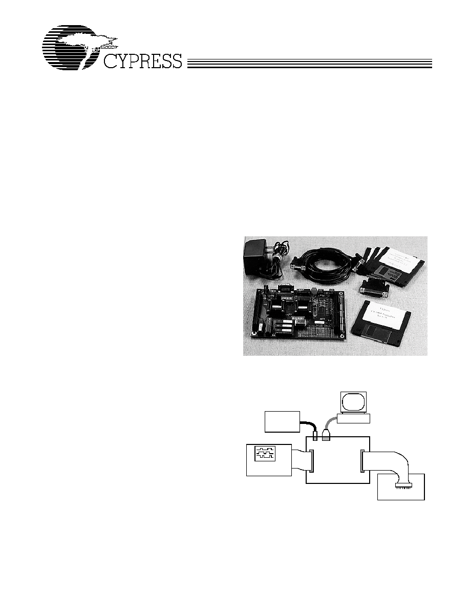
USB Development System on the PC includes:
∑ USB development board
∑ Wall transformer power supply (+6V DC, center negative)
∑ USB cable
∑ RS-232 serial cable
∑ 9-pin male to 25-pin female adapter for RS-232 cable
∑ Registration Card
∑ USB Development System User's Guide
∑ USB Development System Software Guide
∑ USB Development System Software (3 disks)
∑ CYASM Assembler software (1 disk)
∑ Example USB application software included on Assembler
disk
Features
∑ Full development and debug environment for Cypress
Universal Serial Bus Controllers:
-- Real-time, full-speed emulation
-- Software breakpoints
-- Single stepping
-- Register, RAM, I/O display/modification
∑ Debug environment operates without firmware modifi-
cation
∑ User code can be run from on-board EPROM or RAM
∑ Stand-alone operation requires only power connection
∑ Access to key microcontroller internal signals to enable
trace and complex breakpoints
∑ USB Specification Version 1.1 compliant, 1.5 Mbps
speed
∑ Emulator Board Support for Cypress USB IC family:
∑ CY3650
-- CY7C63000/1, 20-pin DIP/SOIC, Windowed DIP
-- CY7C63100/1, 24-pin SOIC, Windowed DIP
-- CY7C63200/1, 18-pin DIP, Windowed DIP
∑ CY3651
-- CY7C63410/1/2, 40-pin PDIP/48-pin SSOP
-- CY7C63413, 40-pin PDIP, 48-pin SSOP, 40-pin Win-
dowed DIP
-- CY7C63510/1/2, 48-pin SSOP
-- CY7C63513, 48-pin SSOP, 48-pin Windowed DIP
Introduction
The Cypress USB Developer's Kit is a powerful tool that en-
ables customers to develop USB hardware and firmware with
emulated Cypress USB ICs. The development system can be
run in two modes. In the typical development system environ-
ment, the board is controlled through a PC-based interface.
Software running on the PC facilitates debugging through
breakpoints, single stepping, and display and modification of
registers and data RAM. In this mode, firmware can be imple-
mented in on-board EPROM, or downloaded to program RAM.
The RAM option provides a quick and easy method for testing
firmware revisions.
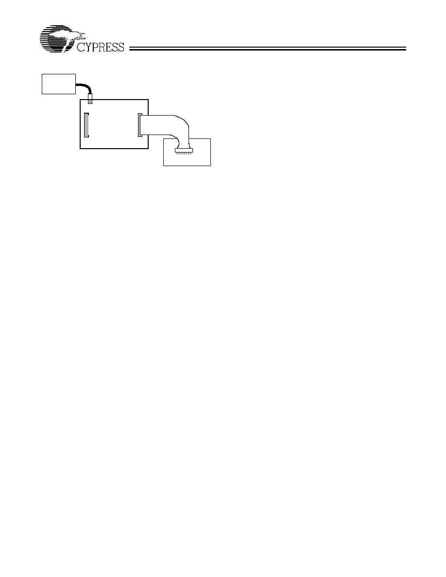
There is also a stand-alone mode which allows portable sys-
tem operation without the PC attached. In this mode, user firm-
ware is programmed in an EPROM, and only power need be
applied to produce a fully operating emulated USB chip.
Additionally, the board may be connected to a logic analyzer
to facilitate full trace capability and complex breakpoints.
USB Development System
PC
Logic Analyzer
(Optional)
Typical USB Development Environment
Development
Board
Target System
Power
Supply
RS-232 To
Serial Port
CY3650
PRELIMINARY
Document #: 38-08003 Rev. **
Page 2 of 5
Hardware Installation
The development system is simple to install and get running.
An enclosed 110 VAC wall transformer supplies power to the
board. (Alternatively, a lab power source can be used.) Once
the included software is installed on a Windows 3.1 or Win-
dows `95 PC, an RS-232 cable connects the board to that PC
to provide a full debug and monitoring environment. The cable
and adapters support both a 9-pin and a 25-pin serial port on
the PC.
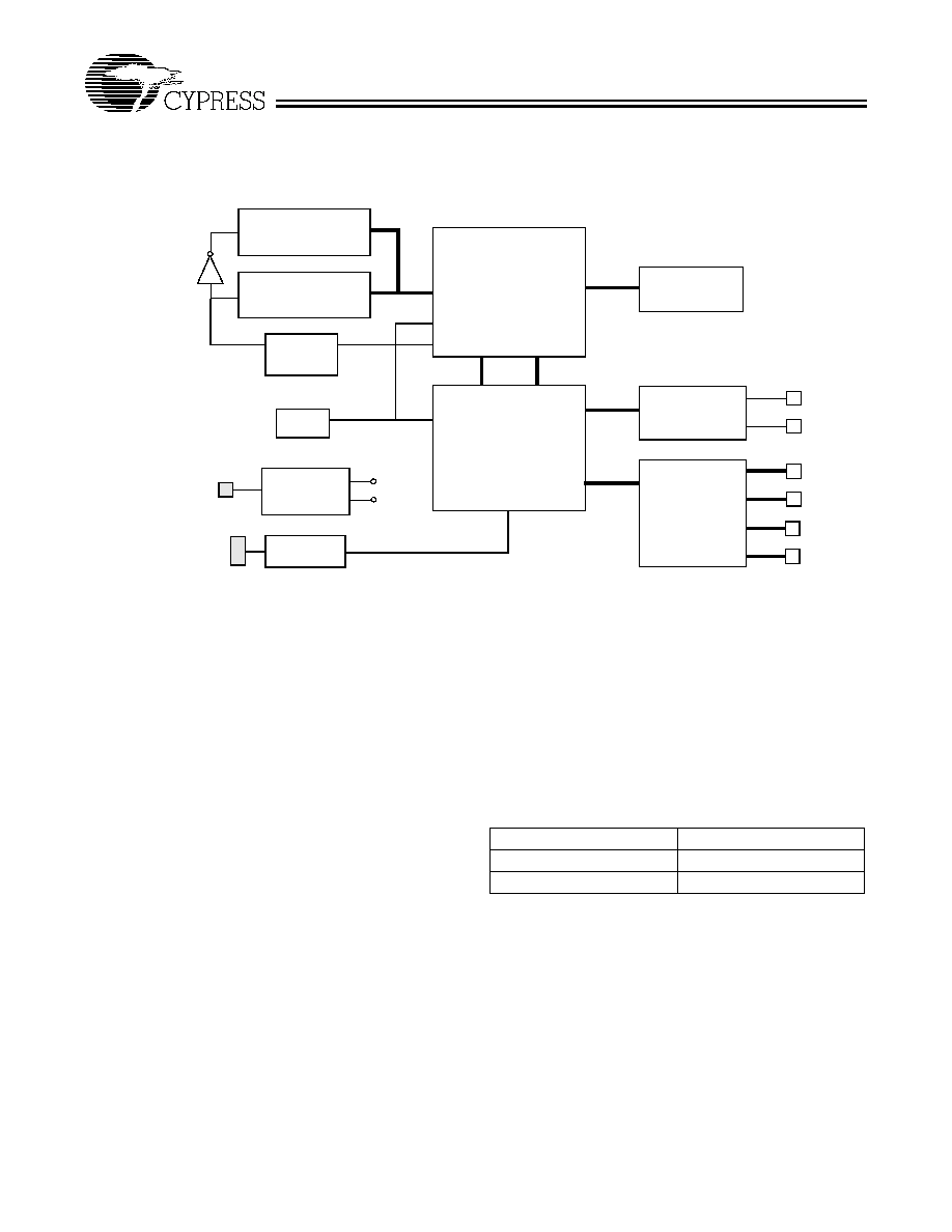
Functional Overview
A block diagram of the development board is shown below,
illustrating the major system components and the user inter-
faces. The microcontroller, USB serial interface protocol en-
gine, and general purpose I/O logic are contained in FPGAs.
The board supports a family of Cypress USB ICs, with varying
amounts of on-chip EPROM, RAM, and I/O. Consult the indi-
vidual device data sheets for details of the IC being emulated.
The Program RAM allows users to download code into
on-board memory. This provides a quick and easy mechanism
for firmware modification. The firmware can be modified after
download by changing individual bytes of code through the
debug interface. The CY3650 board supports program mem-
ory sizes up to 4 KB and the CY3651 board supports program
memory sizes up to 8 KB; consult the data sheet of the actual
target device for the ROM size contained in the IC.
For stand-alone operation, user firmware can be burned into
the supplied UV-erasable EPROM, allowing for operation with-
out the PC attached.
USB Interface
The CY3650 and CY3651 development boards support the
low-speed (1.5 Mbps) USB mode, with a 1.5-k
pull-up resis-
tor to +3.3V on the D
-
line for proper operation.
The USB serial interface protocol engine contains the func-
tions commonly referred to as "Serial Interface Engine" and
"Serial Interface Logic" in USB literature. This provides full
functionality for connecting to a USB bus as a low-speed de-
vice, including endpoint control and automatic NAKing.
I/O Port Operation
The general-purpose I/O ports on the board all operate identi-
cally. As outputs, the ports provide either a (removable) weak
pull-up, or a strong pull-down. During a read operation, the
digital state of all bits of each port are read together. All bits
also have the capability to serve as interrupt inputs, as de-
scribed in the device data sheets.
The versatile 4-bit current-sink DAC per pin, available in many
Cypress USB family ICs, is not implemented on the board.
Support is available for customers who wish to fully emulate
this IC feature
Note: The input thresholds are lower (1.5 V) for the develop-
ment board than the USB parts (45%≠65% V
CC
).
Power
Supply
Stand-Alone Environment
Development
Board
Target System
CY3650
PRELIMINARY
Document #: 38-08003 Rev. **
Page 3 of 5
Signal Access
The development board contains connectors to internal micro-
controller signals and to the emulated I/O pins. A target cable
can be made by the user for the appropriate IC being emulat-
ed.
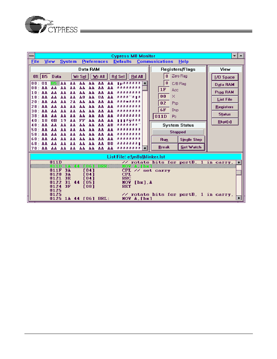
Debug/Monitor Software
The developer's kit software provides a PC interface for debug
control of the microcontroller and all memory and registers.
The debug/monitor function is implemented in hardware, so
modification of the user firmware is not required.
The software allows read/modify access to the following: all
microcontroller internal registers (such as accumulator and
program counters), data RAM, program RAM (or non-modifi-
able EPROM), and all I/O registers. The system allows for mul-
tiple breakpoints and single stepping. At any breakpoint, all
requested data fields are automatically updated, and the list
file tracking moves to the current program line. Figure 1 shows
the debug software window in a typical application.
The software runs under Windows 95 or Windows 3.1. The
only setting that the user needs to provide is the proper COM
port for communication on the serial port and which develop-
ment board is being used.
Assembler
An assembler, which also runs on the PC, is included. The
assembler provides error checking and produces download-
able object code as well as a list file. The assembler supports
USB-specific data types, speeding the development process.
Ordering information
RS-232 To/From PC
Serial Port
USB
Serial Interface
Protocol
Engine
CS
CS
USB
D+
D
-
J6
J13
Power
In
+5V
Reset
Switch
Options
Program RAM
8K x 8
Program ROM
8K x 8
Data RAM
256 x 8
UART
USB
Transceiver
MicroController
S2
Voltage
Regulators
+3.3V
Port0
Port1
CY3650/51 Development Board Functional Block Diagram
Port2
Port3
Port
Transceivers
Ports 2&3
for 3651
only
Part Number
Description
CY3650
USB Developer's Kit
CY3651
USB Developer's Kit
CY3650
PRELIMINARY
Document #: 38-08003 Rev. **
Page 4 of 5
© Cypress Semiconductor Corporation, 2001. The information contained herein is subject to change without notice. Cypress Semiconductor Corporation assumes no responsibility for the use
of any circuitry other than circuitry embodied in a Cypress Semiconductor product. Nor does it convey or imply any license under patent or other rights. Cypress Semiconductor does not authorize
its products for use as critical components in life-support systems where a malfunction or failure may reasonably be expected to result in significant injury to the user. The inclusion of Cypress
Semiconductor products in life-support systems application implies that the manufacturer assumes all risk of such use and in doing so indemnifies Cypress Semiconductor against all charges.
Figure 1. Debug Software Window in Typical Application

CY3650
PRELIMINARY
Document #: 38-08003 Rev. **
Page 5 of 5
Document Title: CY3650 USB Developer's Kit Data Sheet
Document Number: 38-08003
REV.
ECN NO.
Issue
Date
Orig. of
Change
Description of Change
**
110182
10/21/01
SZV
Change from Spec number: 38-00553 to 38-08003