1 of 18
090503
FEATURES
ß Dual fixed-frequency outputs (30kHz to
100MHz)
ß User-programmable on-chip dividers (from 1
to 513)
ß User-programmable on-chip prescaler (1, 2,
4)
ß No external components
ß ±0.5% initial tolerance (commercial)
ß ±1% variation over commercial temperature
and voltage
ß Internal clock, external clock or crystal
reference options
ß 2.7 to 3.6V supply
ß Power-down mode
ß Synchronous output gating
ß Industrial temp operation with relaxed
specifications
PIN ASSIGNMENT
FREQUENCY OPTIONS
Part No.
Max O/P Freq.
DS1073M/Z-100 100.000MHz
DS1073M/Z-80
80.000MHz
DS1073M/Z-66
66.667MHz
DS1073M/Z-60
60.000MHz
DESCRIPTION
The DS1073 is a fixed-frequency oscillator requiring no external components for operation. Numerous
operating frequencies are possible in the range of approximately 27.3kHz to 100MHz through the use of
an on-chip programmable prescaler and divider.
The DS1073 features a master oscillator followed by a prescaler and then a programmable divider. The
prescaler and programmable divider are user-programmable with the desired values being stored in non-
volatile memory. This allows the user to buy an off the shelf component and program it on site prior to
board production. Design changes can be accommodated on the fly by simply programming different
values into the device (or reprogramming previously programmed devices).
The DS1073 is shipped from the factory configured for half the maximum operating frequency. Contact
the factory for specially programmed devices. As alternatives to the onboard oscillator an external clock
signal or a crystal may be used as a reference. The choice of reference source (internal or external) is
user-selectable at the time of programming (or on the fly if the SEL mode is chosen).
The DS1073 features a dual-purpose I/O pin. If the device is powered up in Program mode this pin can be
used to input serial data to the on chip registers. After a Write command this data is stored in non-volatile
memory. When the chip is subsequently powered up in operating mode these values are automatically
restored to the on-chip registers and the I/O pin becomes the oscillator output.
The DS1073 may be operated over either the commercial (T
A
= 0C to 70C) or industrial (T
A
= -40C to +
85C) temperature ranges. AC and DC Electrical Characteristics Tables for operation in both these
temperature ranges are given at the end of the data sheet.
DS1073
3V EconOscillator/Divider
www.maxim-ic.com
I/O
OUT0
V
CC
GND
OSCIN
PDN/SELX
XTAL
OE
1
2
3
4
8
7
6
5
DS1073Z-XXX
150-mil SOIC
DS1073M-XXX
300-mil DIP
XXX = Frequency option
DS1073
2 of 18
The DS1073 is available in 8-pin DIP or SOIC packages, allowing the generation of a clock signal easily,
economically and using minimal board area.
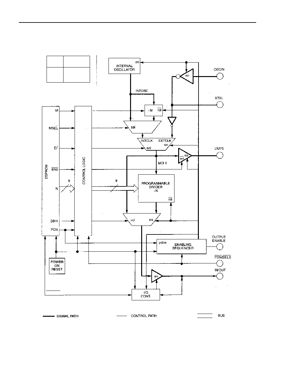
BLOCK DIAGRAM Figure 1
PART
NO.
SUFFIX
INTOSC
FREQUENCY
-100
-80
-66
-60
100.000 MHz
80.000 MHz
66.667 MHz
60.000 MHz

DS1073
3 of 18
PIN DESCRIPTIONS
IN/OUT Pin (I/O): This pin is the main oscillator output, with a frequency determined by clock
reference, M and N dividers. Except in programming mode this pin is always an output. In programming
mode this pin is an input and output.
External Oscillator Input (OSCIN): This pin can be
used to supply an external reference frequency to
the device.
Crystal Oscillator Connection (XTAL): A crystal can
be connected between this pin and OSCIN to
provide an alternative frequency reference. The crystal must be used in fundamental mode. If a crystal is
not used this pin should be left open.
Output Enable Function (OE pin): The DS1073 also
features a "synchronous" output enable. When
OE is at a high logic level the oscillator free runs. When this pin is taken low OUT is held low,
immediately if OUT is already low, or at its next high-to-low transition if OUT is high. This prevents any
possible truncation of the output pulse width when the enable is used. While the output is disabled the
master oscillator continues to run (producing an output at OUT0, if the
EN0
bit = 0) but the internal
counters (/N) are reset. This results in a constant phase relationship between OE's return to a high level
and the resulting OUT signal. When the enable is released OUT will make its first transition within one
to two clock periods of the master clock.
Power-Down/Select Function (
PDN
/
SELX
pin): The
Power-Down/Select (
PDN
/
SELX
) pin has a user-
selectable function determined by one bit (PDN bit) of the user-programmable memory. According to
which function is selected, this pin will be referred to as
PDN
or
SELX
.
If the Power-Down function is selected (PDN bit = 1) a low logic level on this pin can be used to make
the device stop oscillating (active low) and go into a reduced power consumption state. The "Enabling
Sequencer" circuitry will first disable OUT in the same way as when OE is used. Next OUT0 will be
disabled in a similar fashion. Finally the oscillator circuitry will be disabled. In this mode both outputs
will go into a high-impedance state.
The power consumption in the power-down state is much less than if OE is used because the internal
oscillator (if used) is completely powered down. Even if an external reference or a crystal is used all of
the on-chip buffers are powered down to minimize current drain. Consequently the device will take
considerably longer to recover (i.e., achieve stable oscillation) from a power-down condition than if the
OE is used.
If the Select function is chosen (PDN bit = 0) this pin can be used to switch between the internal
oscillator and an external reference (or crystal) on the fly. When this mode is chosen the E/
I
select bit is
overridden, a high logic level on
SELX
will select the internal oscillator, a low logic level will select the
external reference (or crystal oscillator).
Reference Output (OUT0 pin): A reference output,
OUT0, is also available from the output of the
reference select mux. This output is especially useful as a buffered output of a crystal defined master
frequency. OUT0 is unaffected by the OE pin, but is disabled in a glitchless fashion if the device is
powered down. If this output is not required it can be permanently disabled by setting the
EN0
bit to 1,
and there will be a corresponding reduction in overall power consumption.

DS1073
4 of 18
USER-PROGRAMMABLE REGISTERS
The following registers can be programmed by the user to determine operating frequency and mode of
operation. Details of how these registers are programmed can be found in a later section, in this section
the function of the registers are described. The register settings are non-volatile, the values being stored
automatically in EEPROM when the registers are programmed. Note: The register bits cannot be used to
make mode or frequency changes on the fly. Changes can only be made by powering the device up in
"Programming" mode. For them to be become effective the device must then be powered down and
powered up again in "Operation" mode.
For programming purposes the register bits are divided into two 9-bit words: the MUX word determines
mode of operation and prescaler values; the DIV word sets the value of the programmable divider.
MUX WORD Figure 2
(MSB)
(LSB)
0*
0*
0*
EN0
PDN
M
MSEL
DIV1
E/
I
*These bits must be set to 0
E/
I
This bit selects either the internal oscillator or the external/ crystal reference.
1 = External/Crystal
0 = Internal Oscillator
however, if the PDN bit is set to 0 the E/
I
bit will be overridden by the logic level on the
PDN
/
SELX
pin.
Table 1
PDN
BIT
E/
I
( PDN
/ SELX
PIN
OSCILLATOR MODE
0
X
0
EXTERNAL/CRYSTAL
0
X
1
INTERNAL
1
X
0
POWER-DOWN
1
0
1
INTERNAL
1
1
1
EXTERNAL/CRYSTAL
DIV1
This bit allows the master clock to be routed directly to the output (DIV1 = 1). The N programmable
divider is bypassed so the programmed value of N is ignored. The frequency of the output (f
OUT
) will be
INTCLK or EXTCLK depending on which reference has been selected. If the Internal clock is selected
the M prescaler may still be used, so in this case f
OUT
= INTOSC/M (which also equals MCLK and
INTCLK). If DIV1 = 0 the programmable divider functions normally.
MSEL
This bit determines whether or not the M prescaler is bypassed.
MSEL
= 1 will bypass the prescaler.
MSEL
= 0 will switch in the prescaler, with a divide-by number determined by the M bit.
M
This bit sets the divide-by number for the prescaler. M = 0 results in divide-by-4, M = 1 results in divide-
by-2. The setting of this bit is irrelevant if
MSEL
= 1.

DS1073
5 of 18
Table 2
DIV1
BIT
E/
I
BIT*
MSEL
BIT
M
BIT
OPERATION
0
0
0
0
INTERNAL OSCILLATOR DIVIDED BY 4*N
0
0
0
1
INTERNAL OSCILLATOR DIVIDED BY 2*N
0
0
1
X
INTERNAL OSCILLATOR DIVIDED BY N
0
1
X
X
EXTERNAL OSCILLATOR DIVIDED BY N
1
0
1
X
INTERNAL OSCILLATOR DIVIDED BY 1
1
0
0
0
INTERNAL OSCILLATOR DIVIDED BY 4
1
0
0
1
INTERNAL OSCILLATOR DIVIDED BY 2
1
1
X
X
EXTERNAL OSCILLATOR DIVIDED BY 1
*Assuming PDN bit = 1, otherwise internal/external selection will be controlled by the
PDN
/
SELX
pin.
DIV WORD Figure 3
(MSB)
(LSB)
N (9-BITS)
PDN
This bit is used to determine the function of the
PDN
/
SELX
pin. If PDN = 0, the
PDN
/
SELX
pin can be
used to determine the timing reference (either the internal oscillator or an external reference/crystal). If
PDN = 1, the
PDN
/
SELX
pin is used to put the device into power-down mode.
EN0
This bit is used to determine whether the OUT0 pin is active or not. If
EN0
= 1, OUT0 is disabled (High-
impedance). If
EN0
= 0, the internal reference clock (MCLK) is output from OUT0. The OE pin has no
effect on OUT0, but OUT0 is disabled as part of the power-down sequence.
N
These nine bits determine the value of the programmable divider. The range of divisor values is from 2 to
513, and is equal to the programmed value of N plus 2:
Table 3
BIT
VALUES
DIVISOR (N)
VALUE
000000000
000000001
.
.
.
.
.
111111111
2
3
.
.
.
.
.
513
NOTE:
The maximum value of N is constrained by the minimum output frequency. If the internal clock is
selected, INTOSC/(M*N) must be greater than f
OUTmin
; if the external clock is selected, EXTCLK/N must
be greater than f
OUTmin
. (If DIV1 = 1, then INTOSC or EXTCLK, as applicable, must exceed f
OUTmin
).