 | –≠–ª–µ–∫—Ç—Ä–æ–Ω–Ω—ã–π –∫–æ–º–ø–æ–Ω–µ–Ω—Ç: DS1802 | –°–∫–∞—á–∞—Ç—å:  PDF PDF  ZIP ZIP |
1 of 17
101999
FEATURES
ß
Ultra-low power consumption
ß
Operates from 3V or 5V supplies
ß
Two digitally controlled, 65-position
potentiometers including mute
ß
Logarithmic resistive characteristics (1 dB
per step)
ß
Zero-crossing detection eliminates noise
caused by wiper movement
ß
Digital or mechanical pushbutton wiper
control
ß
Serial port provides means for setting and
reading both potentiometers wipers
ß
20-pin SOIC and 20-pin TSSOP for surface
mount applications
ß
Operating Temperature Range:
-40
∞
C to +85
∞
C
ß
Software and hardware mute
ß
Resistance Available: 45 k
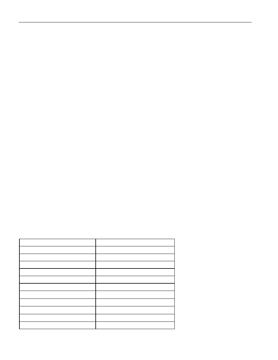
PIN ASSIGNMENT
PIN DESCRIPTION
L0, L1
- Low End of Resistor
H0, H1
- High End of Resistor
W1,W2
- Wiper End of Resistor
V
CC
- 3V/5V Power Supply Input
RST
- Serial Port Reset Input
D
- Serial Port Data Input
CLK
- Serial Port Clock Input
MODE
- Mode Select Input
UC0, UC1
- Up Control Pushbutton Inputs
DC0, DC1
- Down Control Pushbutton
Inputs
VU, VD
- Volume-Up/Volume-Down
Inputs
B0, B1
- Balance Pot-0, Pot-1 Inputs
GND
- Digital Ground
MUTE
- Mute
AGND
- Analog Ground
ZCEN
- Zero-Crossing Detect Input
C
OUT
- Cascade Output
DS1802
Dual Audio Taper Potentiometer
With Pushbutton Control
www.dalsemi.com
GND
1
20
VCC
COUT
2
19
VU (UC1)
CLK
3
18
VD (DC1)
D
4
17
B0 (UC0)
RST
5
16
B1 (DC0)
ZCEN
6
15
MUTE
MODE
7
14
AGND
W0
8
13
H1
L0
9
12
L1
H0
10
11
W1
20-Pin DIP (300-mil)
20-Pin SOIC (300-mil)
20-Pin TSSOP (173-mil)
See Mech. Drawings Section
DS1802
2 of 17
101999
DESCRIPTION
The DS1802 is a dual audio taper-potentiometer having logarithmic resistive characteristics over the
device range. Each potentiometer provides 65 wiper positions with a 1 dB increment per step and device
mute. The DS1802 has two methods of device control, which include contact closure (pushbutton) inputs
and a 3-wire serial interface for wiper positioning. The pushbutton control inputs provide a simple
interface for device control without the need for a CPU. While the 3-wire serial interface, using a CPU,
provides the user the ability of reading or writing exact wiper positions of the two potentiometers. The
DS1802 can also be configured to operate in either independent or "stereo" modes when using pushbutton
control. Independent mode of operation allows for independent wiper control, and stereo mode of
operation provides single input control over both potentiometer wiper positions. The DS1802 is offered in
commercial temperature versions. Packages for the part include a 20-pin DIP, 20-pin SOIC, and 20-pin
TSSOP.
OPERATION
The DS1802 provides two 65-position potentiometers per package, each having a logarithmic resistive
characteristic as shown in Table 1. The DS1802 can be controlled either digitally or mechanically using a
3-wire serial interface or contact closure input, respectively. The pushbutton interface allows for a simple
mechanical control method for incrementing or decrementing wiper position. The 3-wire serial interface
is designed for CPU controlled applications and allows the potentiometer's exact wiper position to be
read or written. Additionally, the DS1802 can be daisy-chained for multi-device environments.
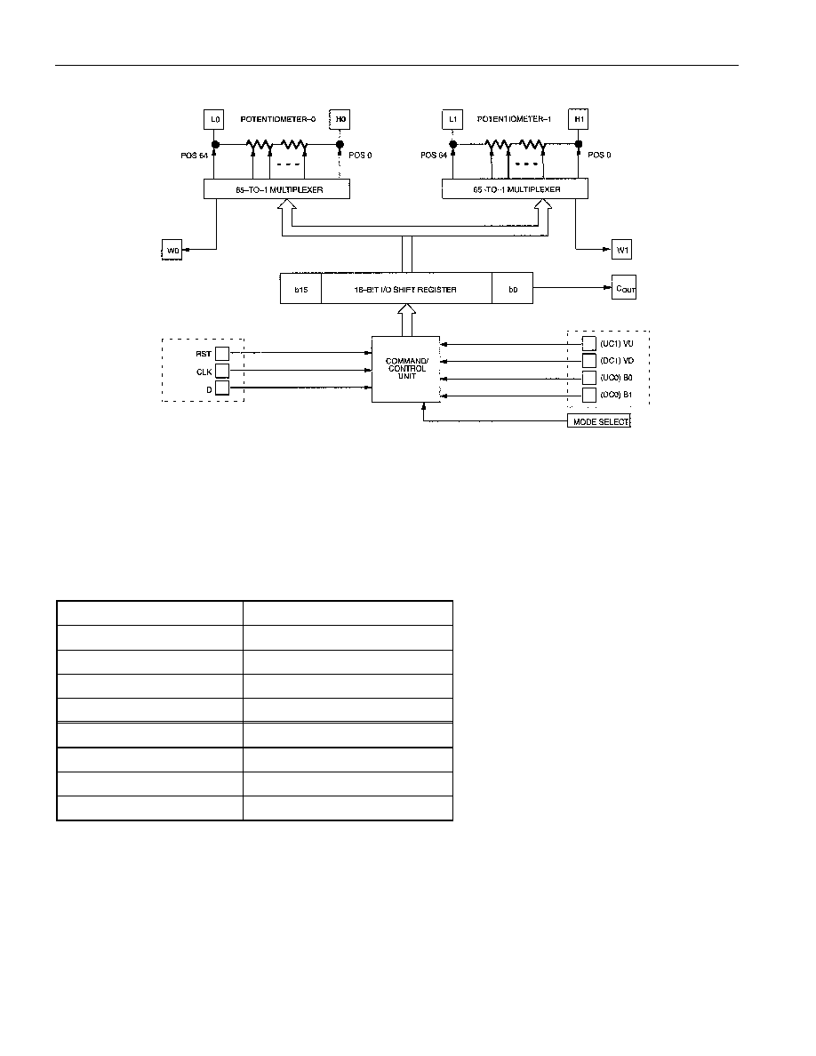
Figure 1 presents a block diagram of the DS1802. As shown, the inputs from the 3-wire serial interface
and contact closure inputs drive a command/control unit. The command/control unit interprets these
inputs for control of the two potentiometers.
The MODE input is used for contact closure operation. This input allows the user to choose between
independent mode control and stereo mode control. The MODE input is discussed in detail under the
contact closure interface control.
On power-up the serial port is stable and active within 10 microseconds. The contact closure control
interface inputs are active after 50 ms. The wiper position on power-up will be at position 63, the low end
of the potentiometer. Position 64 is the mute level.
RESISTANCE CHARACTERISTICS Table 1
POSITION
OUTPUT LEVEL (dB)
0
0
1
-1
2
-2
3
-3
4
-4
5
-5
∑
∑
∑
∑
∑
∑
63
-63
64(mute)
<-90
DS1802
101999
3 of 17
DS1802 BLOCK DIAGRAM Figure 1
CONTACT CLOSURE INTERFACE CONTROL
The DS1802 can be configured to operate from contact closure inputs sometimes referred to as
pushbutton control. There exists a total of four physical contact closure terminals on the device package.
When combined with the MODE input, these contact closure inputs provide a total of eight different
contact closure functions. These eight contact closure functions are listed in Table 2.
CONTACT CLOSURE INPUTS Table 2
CONTACT INPUT
DESCRIPTION
UC0*
Up contact potentiometer-0
UC1*
Up contact potentiometer-1
DC0*
Down contact potentiometer-0
DC1*
Down contact potentiometer-1
VU**
Volume-up
VD**
Volume-down
B0**
Balance Pot-0
B1**
Balance Pot-1
* independent mode control
** stereo mode control
The MODE input terminal is used to select the mode of wiper control using contact closure. There exist
two modes of wiper control, which include independent mode control and stereo mode control. As shown
in the pin assignment diagram, the contact closure inputs share pins. Input functionality is determined by
the state of the MODE input at power-up.

DS1802
101999
4 of 17
Independent mode control allows the user to independently control each potentiometer's wiper position.
For independent mode control, the MODE input should be in a high state. For stereo mode control, the
MODE input should be in a low state. The input should always be tied to a well-defined logic state.
The contact closure inputs which affect independent mode control include UC0, UC1, DC0, and DC1. As
outlined in Table 2, the UC0 and UC1 inputs are used to move the potentiometers wipers towards the
high end of the potentiometer (H0, H1) terminals. The DC0 and DC1 inputs control movement towards
the low-end terminals (L0, L1). Note that UC0 and DC0 control potentiometer-0 wiper movement while
UC1 and DC1 control potentiometer-1 movement.
An additional feature of the contact closure interface is the ability to control both directions of wiper
movement with only the UC0 and UC1 contact closure inputs. This feature is referred to as single
pushbutton operation. Figure 2(a) and (b) illustrates both configurations for single pushbutton and dual
pushbutton operation.
Stereo Mode Control
Stereo mode control allows for the simultaneous positioning of both potentiometer wipers from a single
control input. Stereo mode control is entered when the MODE select input is in a low state at power-up.
The functionality available when operating in stereo mode control includes: 1) volume-up, 2) volume-
down, 3) balance-0, and 4) balance-1.
Volume Control Inputs
Volume-up and volume-down allow the user to move both wipers either up or down the resistor array
without changing the relative balance or distance between the wipers. For example, if potentiometer-0's
wiper is set at position 28 and potentiometer-1's wiper is set at position 20, the position distance of eight
is maintained when using either of these functions. Additionally, the balance between both wipers is
preserved if either reaches the end of its resistor array.
Balance Control Inputs
Balance control inputs allow the user to control the distance or offset between potentiometer-0 and
potentiometer-1 wiper position settings. The two input controls for balance include B0 and B1. The
balance control inputs attempt to minimize their respective wiper's attenuation. When the DS1802 first
receives a balance control input, the position of the wiper closest to the high end terminal, H X , is stored.
Wiper position movement is then governed by this stored value.
For example, if the B0 input is used, the attenuation of potentiometer-0 will change only if it is greater
than the attenuation of potentiometer-1. The direction of movement for the potentiometer-0 wiper will be
towards the high end of the resistor array. Movement of wiper-0 will only stop once its value is equal to
that of wiper-1. At this point, continued input activity on the B0 input will cause an increase in
attenuation of potentiometer-1. Note that if the wiper of potentiometer-1 peaks at the bottom of its array,
continued B0 input activity will cause no change in the wiper positions of the device. A B1 input will be
required to change the balance of the two wipers if the potentiometer wiper peaks in this case.
In the case where both wiper positions are at position 63, no movement of the wipers will take place
when using the balance controlled inputs. A volume-up control input is required to move the wiper
positions from the bottom of the resistor arrays. Balance control operation is presented in Figure 3.

DS1802
101999
5 of 17
SINGLE PUSHBUTTON CONFIGURATION Figure 2(a)
DUAL PUSHBUTTON CONFIGURATION Figure 2(b)
Contact closure is defined as the transition from a high level to a low level on the contact closure input
terminals. The DS1802 interprets input pulse widths as the means of controlling wiper movement. A
single pulse input over the UCx or DCx input terminals will cause the wiper to move one position. A
transition from high to low on these inputs is considered the beginning of pulse activity or contact
closure. A single pulse is defined as being greater than 1 ms but lasting no longer than a second. This is
shown is Figure 4(a).
Repetitive pulsed inputs can be used to step through each resistive position of the device in a relatively
fast manner (see Figure 4(b)). The requirement for repetitive pulsed inputs is that pulses must be
separated by a minimum time of 1 ms. If not, the DS1802 will interpret repetitive pulses as a single pulse.