DMS Accessories
4-Wire DC Current Shunts
Æ
Æ
These shunts are designed for use with 50 or 100 millivolt
measuring instruments, calibrated in terms of the ampere ratings of
the shunt. The accuracy of these shunts is better than ±1/4% of
the rated value and the temperature coefficient is ±0.000015. It is
important that the resistance be constant under different tempera-
ture conditions. It is usually assumed that the maximum temperature
will be about 80∞C and the usual range is
≠40∞ to +60∞C.
For continuous operation, it is recommended that shunts are
not run at more than two-thirds (2/3) the rated current under
normal conditions of use as per IEEE standards.
If the shunt is used in an AC or pulse current environment make
sure that the highest pulse current will not exceed the recom-
mended two-thirds, the rated current for continuous operation. In
this case, the average millivolt reading using an rms meter will be
proportional with the duty cycle of the AC current.
1.0 INSTALLATION
By definition, a shunt is a resistor, and will generate heat with
passage of current. Because of this, the resistance blades of the
shunt should be mounted in a vertical position to promote free
convectional flow of air. Where this mounting position is impractical
and in installations where the shunt is in a confined location,
forced air cooling should be provided. Under no condition should
the manganin shunt strip be allowed to surpass 145∞C, as this will
cause a permanent change in resistance.
Shunts should be installed to protect them from damage by
thermal expansion forces in the connecting bus bars or by short
circuit forces. It should be recognized that shunts are inherently
weaker than their current connections and that special flexibility
may be needed at times.
Where possible all shunts should be connected in the
grounded side of the line. See Figures 1 and 2. Portable type
shunts, with an insulating base, when used on circuits above 750
volts should be mounted in the grounded side of the circuit. Where
more than one bus bar is to be connected to each end of a single
terminal shunt, these bars should be distributed as equally as
possible on each side of the shunt terminals.
POINTS TO KEEP IN MIND WHEN YOU USE A
DC AMMETER SHUNT
2.0 SHUNT SELECTION GUIDE
Selection of ratings should be based on operation at a normal
current of 2/3 the rated value. Ratings are based on mountings in
accordance with Reference Test Conditions:
∑ Reference Temperature: 25∞C (±2∞C)
∑ Position: Current terminals and resistance blades, vertical,
allowing free air circulation.
∑ Connections: Tightly bolted to current bus using all terminal
slots and specified depth of blade insertion or tightly bolted to
lugs with cables or proper crosssection.
Since a shunt is essentially part of a bus-bar assembly, it
depends on the structure to conduct away a major portion of the
heat generated within the shunt and then to radiate this heat. It is
important, therefore, that these connecting buses be of ample size
and properly attached to the shunt.
3.0 DESIGN CONSIDERATIONS
When trying to find the correct shunt rating to specify for a
given application, there are four things to take into account:
A. Duty ≠ continuous, intermittent or surge
B. Ambient ≠ elevated temperature or high altitudes
C. Temperature rise ≠ normal or limited
D. Environment ≠ grouped, enclosed, forced air
E. Combinations of A through D
Although each of these conditions will be considered sepa-
rately, any combination of them may exist in a specific case. When
this happens it will be necessary to use more than one of the
following sections to arrive at the correct rating.
4.0 DUTY
For duty which is less than continuous, a shunt need not be
rated as high as a straight calculation based on resistance and
voltage or current would indicate. If, for instance the shunt is
repeatedly energized for a short period (not to exceed 5
minutes)...a conservative rating may be obtained as follows:
12
11
3
7
8 4
1
DMS-20PC-0-RL
DC LOAD
Power Supply
DC
LOAD
2
Isolated
5Vdc
Power
DC
CURRENT
SHUNT
12
11
3
7
8 4
1
DMS-20PC-0-RL
5Vdc
POWER
SUPPLY
DC
LOAD
2
DC
CURRENT
SHUNT
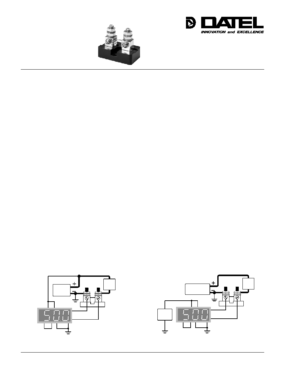
Figure 1. Shunt connected on the low side with the meter
powered from the same supply.
Figure 2. Shunt connected on the low side with the meter
powered from an isolated power supply.
Order on-line at www.datel.com

DATEL, Inc. 11 Cabot Boulevard, Mansfield, MA 02048-1151
Tel: (508) 339-3000 (800) 233-2765 Fax: (508) 339-6356
Internet: www.datel.com
Email: sales@datel.com
DATEL (UK) LTD. Tadley, England Tel: (01256)-880444
DATEL S.A.R.L. Montigny Le Bretonneux, France Tel: 01-34-60-01-01
DATEL GmbH M¸nchen, Germany Tel: 89-544334-0
DATEL KK Tokyo, Japan Tel: 3-3779-1031, Osaka Tel: 6-6354-2025
DATEL makes no representation that the use of its products in the circuits described herein, or the use of other technical information contained herein, will not infringe upon existing or future patent rights. The descriptions contained herein do not imply the granting of licenses
to make, use, or sell equipment constructed in accordance therewith. Specifications are subject to change without notice. The DATEL logo is a registered DATEL, Inc. trademark.
K1
D
where D is the ratio of ON time to the total period.
Ppuls = Pmax / K1
Pmax = Prated x 0.66
Pmax = maximum continuous power
Prated = catalog rated power
Ppuls = maximum pulsating power
For surge and pulse service a different approach must be
used. In these cases it is necessary to provide enough thermal
mass to absorb the energy to be dissipated and be sure that the
construction of the shunt is adequate to accommodate the peak
power. Therefore, it is recommended that a complete description
of the pulse/surge wave shape or circuit constants and operating
conditions be submitted to DATEL for the selection of a suitable
shunt.
5.0 AMBIENT
If the ambient temperature of the area in which the shunt is to
operate exceeds the ambient Reference Test Conditions, a de-
rating factor must be applied to prevent the manganin temperature
from going above the safe limit of 125∞C. The following formula
may be used to find the de-rating power.
Pout = Pmax x (1-T/ A)
Pmax = Prated x 0.66
where T is the difference between the rated and operating ambient
temperatures, A is the rise allowed above the rated ambient and
Pmax is the Pout at 25∞C.
Example: A 800 Amp 50mV shunt is energized for 15 seconds
of each minute.
D = 15 / 60 = 0.25 and
K1
0.25
= 0.5 thus,
Prated = 800 x 0.05 = 40 watts
Pmax = Prated x 0.66 = 40 x 0.66 = 26.4 watts
Ppuls = Pmax / K1 = 26.40 / 0.5 = 52.8 watts
therefore this shunt can be loaded up to 919 Amps.
Example: If a 150 Amp 50 mV shunt is to operate in a 100∞C
ambient, what is the maximum load? 100∞C is 75 degrees above
the ambient, so T = 75∞C, and the rated rise A is 100∞C.
Therefore:
Pout = Pmax x (1-(75 / 100)) = Pmax x 0.25 Pmax = 0.66
x Prated = 0.66 x (150 x 0.05) = 4.95 watts
Pout for an ambient of 100∞C is Pout = 4.95 x 0.25 = 1.23
watts, 60 Amps will be the maximum load.
6.0 TEMPERATURE RISE
In many cases it is desirable to limit the temperature rise of a
shunt for increased accuracy and stability or to protect other
equipment near it. A satisfactory derating factor "K2" may be
obtained from:
K2 = 1 - t / 125
where "t" is the difference between the rated and the
newly imposed rise limit.
Example: Suppose it is necessary to limit the temperature rise
of a shunt type LC800 Amp 50 mV to 75∞C. What is the maximum
safe load?
t =125-75 =50
K2 =1 -(50 / 125) =0.6
Pmax = Prated x 0.66 =26.4 watts at 25∞C
K2 x Pmax = 26.4 x 0.6 = 15.84 watts;
therefore 503 Amps represents the maximum safe load.
DMS-20PC-0-RL
DC LOAD
Power Supply
11
12
3
7
8 4
Isolated
5Vdc
Power
1 2
DC
LOAD
DC
CURRENT
SHUNT
1.75"
1.5"
3.25"
0.20" DIA
2 PLACES
8-32 SCREW
2 PLACES
1.75"
0.562"
0.43"
0.75"
3/8-16 x 5/8
0.62"
0.62"
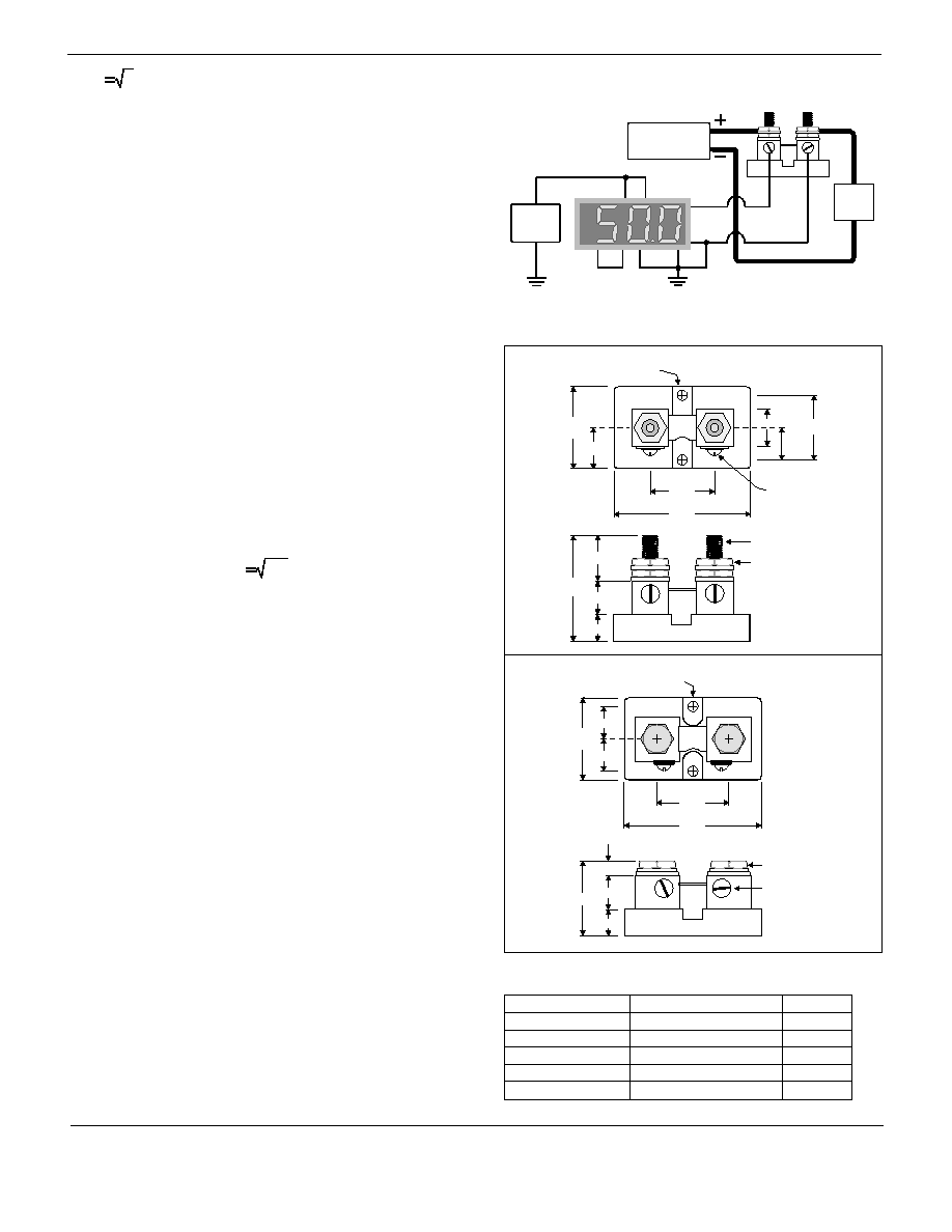
Figure 3. Shunt connected on the high side with the meter
powered from an isolated power supply.
1.25"
0.62"
1.0"
2.0"
0.20" DIA
2 PLACES
8-32 SCREW
2 PLACES
0.87"
0.50"
0.43"
1.68"
0.56"
0.62"
0.50"
1/4-28 UNF
STUD
1/4-28 UNF
HEX JAM NUT
Figure A
Figure B
DS-0480B 2/02
ORDERING INFORMATION
DATEL Part Number
39-1734102
39-1734101
39-1734109
39-1734119
39-1734120
Current Shunt
5A
50mV
50A
50mV
500A
50mV
10A
100mV
100A
100mV
Figure
A
A
B
A
A

