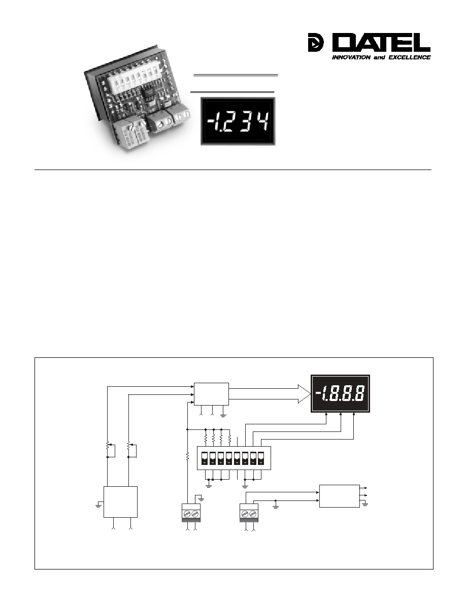
DMS-20PC-0/5
0-5V and 0-10V Input
3Ω Digit, LED Display
Process Control Monitors
Actual Size
∑∑
∑∑
∑
Accepts 0-5V and 0-10V inputs
∑∑
∑∑
∑
Large, easy-to-read, 0.37"/9.4mm
LED display
∑∑
∑∑
∑
Choice of 6 LED power/color options
∑∑
∑∑
∑
High input impedance, 100k
∑∑
∑∑
∑
+5V to +40V model draws 9mA typ.
∑∑
∑∑
∑
Miniature size: 1.38" x 1.25" x 0.95"
∑∑
∑∑
∑
High-quality, 20-turn, span (gain) and
zero (offset) adjustments
∑∑
∑∑
∑
DIP-switch selectable range and
decimal points
∑∑
∑∑
∑
Vibration-resistant package; Reliable
screw-terminal input connections
∑∑
∑∑
∑
Hundreds of different input/readout
combinations
Features
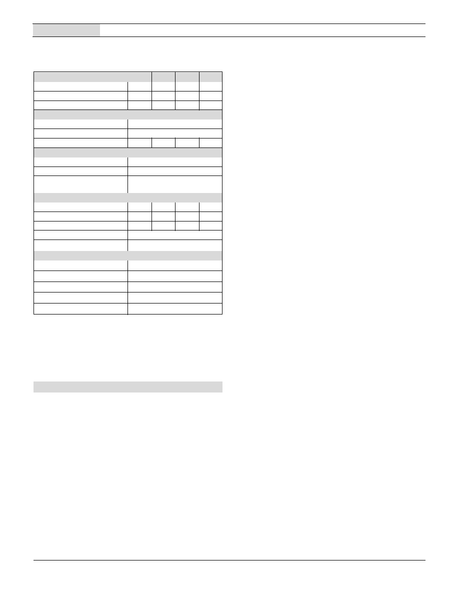
Figure 1. DMS-20PC-0/5 Simplified Schematic
DATEL's DMS-20PC-0/5 Series are the world's smallest, full-featured, 0-5V input
process control monitors. Their large, easy-to-read, 0.37"/9.4mm LED displays are
available in a choice of 5 LED color/intensity options: standard red, standard green,
super-bright red, super-bright blue and low-power red. Two power supply input ranges
are also available: the industry-standard +5V and a wide-range +5V to +40V (which
typically draws 9mA at +24V).
Gain (span) and offset (zero) adjustments are performed with on-board, precision,
20-turn potentiometers. All decimal-point and range-change selections are made on
an 8-position, vibration-resistant, gold-plated DIP switch. Unlike competitive meters,
there are no jumpers or solder gaps to open or close, and to further enhance
reliability, the entire assembly utilizes 100% soldered connections. Both power-supply
and input-signal connections are made via reliable screw-type terminal blocks.
The DMS-20PC-0/5's DIP switch and potentiometers accommodate hundreds of
input-voltage/output-reading combinations. This practically eliminates the need for
more costly, long-lead-time, factory "specials" in applications which use several
different-range meters. An accessory bezel assembly≠≠featuring metal fasteners and
a rubber gasket≠≠simplifies panel mounting and also provides excellent resistance
to environmental dust and moisture. All these outstanding features combine to make
the DMS-20PC-0/5 the perfect meter for prototype and OEM, 0-5V input, process
control monitoring.
DATEL, Inc., Mansfield, MA 02048 (USA)
∑
Tel: (508)339-3000, (800)233-2765 Fax: (508)339-6356
∑
Email: sales@datel.com
∑
Internet: www.datel.com
Æ
Æ
Order on-line at www.datel.com
Super-Bright Blue
LED Models
NEW!
D P 3
D P 2
D P 1
+ V
T B 2
D M S - 2 0 P C - 0 / 5
S i g n a l I n p u t
+
T B 1
V
+
Z e r o
A d j u s t
R 3
R 7
G a i n
A d j u s t
B a n d - G a p
R e f e r e n c e
C i r c u i t
H I L O
+ 5 V
5 V
3 Ω D i g i t
A / D C o n v e r t e r
+ 5 V
5 V
D I P S w i t c h e s
+ 5 V
D C / D C
C o n v e r t e r
P o w e r S u p p l y I n p u t
D A T A
5 V
N . C .
N . C .
O N
1
2
3
4
5
6
7
8
1
2
1
2
DMS-20PC-0/5
0 - 5 V I N P U T , 3 Ω D I G I T , L E D D I S P L A Y P R O C E S S C O N T R O L M O N I T O R S
Ordering Information
DMS-20PC-0/5-5RS
+5V supply, standard-intensity red LED's
DMS-20PC-0/5-5GS
+5V supply, standard-intensity green LED's
DMS-20PC-0/5-5BS
+5V supply, bright blue LED's
DMS-20PC-0/5-5RL
+5V supply, low-power red LED's
DMS-20PC-0/5-5RH
+5V supply, high-intensity red LED's
DMS-20PC-0/5-24RL
+5V to +40V supply, low-power red LED's
DMS-PS1-CM
+5V /1.0A AC/DC power supply module
DMS-PS4-CM
+24V /0.45A AC/DC power supply module
DMS-PS7-CM
+24V /0.7A AC/DC power supply module
DMS-BZL3
Bezel assembly
DMS-BZL4
Bezel assembly with sealing gasket
DMS-20-CP
Panel cutout punch
Note: Standard panel-mount applications MUST use either DMS-BZL3 or
DMS-BZL4 bezel assemblies. See Mechanical Specifications section for
cutout/drill dimensions.
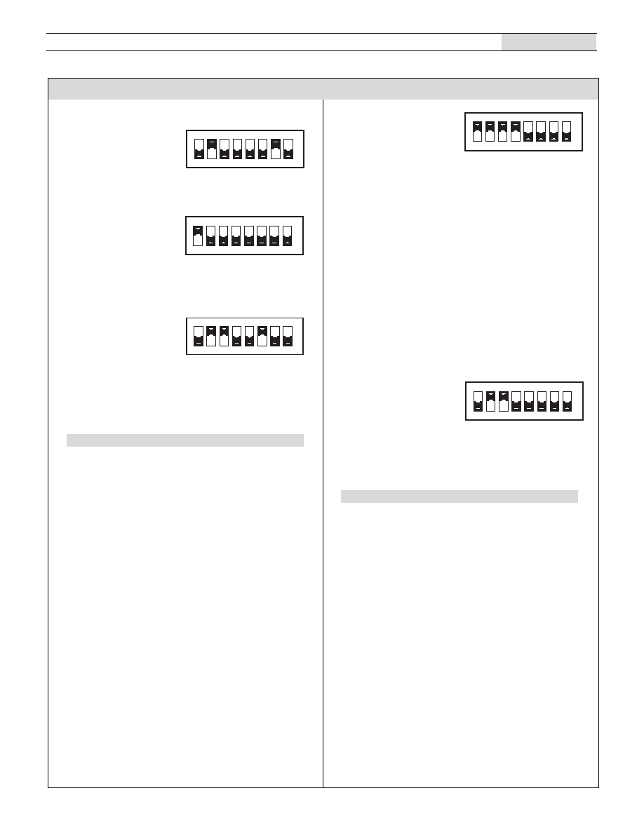
As shipped, the DMS-20PC-0/5 is factory calibrated to read
"000" for a 0.0V input and "1999" for a 5.0V input. The following
worst-case procedure assumes the DMS-20PC-0/5 is com-
pletely mis-adjusted, i.e., both potentiometers and the DIP
switches are randomly set.
1. Set R7 (full scale span/gain adjust) and R3 (zero/offset
adjust) fully clockwise, roughly 22 turns, and place SW1-
SW8 to OFF (down position).
2. Select DIP switch setting #1 in Table 1.
3. Apply a precision 0.0V input and adjust R3 until the meter's
display reads "000".
4. Apply a precision 5.0V input and adjust R7 until the meter's
display reads "1999". Repeat steps 3 and 4 to make sure the
adjustments do not affect one another.
5. Select the appropriate decimal point by setting SW6, SW7 or
SW8 to ON (DP1, DP2 or DP3 respectively).
NOTE: The "000" to "1999" display readings referred to in
the instructions above are for illustrative purposes only. If
other display readings such as "000" to "1200" are desired,
refer to the DIP-Switch Settings Tables for SW1-SW4
settings. (SW5 is reserved for future use, it has no affect on
display operation.) The initial setting of R3 and R7 fully
clockwise is recommended in the adjustment procedure for
all the following examples.
Operating and Setup Instructions
The DMS-20PC-0/5 can also be used in most 0-10V applications. See the section
on 0-10V inputs for more information. See Note 3 on Table 1.
INPUT LO (TB1 "≠LO") is internally connected to the power return (TB2 "≠V").
Overvoltage specifications apply to the INPUT HI (TB1 "+HI") connection.
Technical Notes
1. Input Configuration: The DMS-20PC-0/5 has its input low terminal
(TB1 "LO") internally connected to the power supply ground terminal
(TB2 "≠V"). This connection effectively places the meter's input in a
single-ended configuration. In some applications, single-ended inputs
can cause ground-loop induced errors (the meter's display becomes
unstable or bounces). This occurs because the LED drive currents
flow through both the ≠V terminal and the signal LO terminal.
If suspected ground-loop errors are encountered, and the input signal
LO terminal is externally connected to ≠V somewhere else in the
system, try removing the connection to TB1 "LO". Inputs which have
no ground-return connection to ≠V (commonly referred to as "floating
inputs") must have their most negative potential tied to TB1 "LO".
Please consult DATEL for more information.
Applications which require electrical isolation between the input
signal source and the system power supply must use a separate
transformer-isolated supply to power the meter.
2. Panel Mounting: In most standard through-the-panel installations,
the DMS-20PC-0/5 must be secured to the panel with either DMS-
BZL3 or DMS-BZL4 optional bezel assemblies (see the Mechanical
Specifications section and the Ordering Guide for more information).
The metal retaining clip supplied with other DMS-20 Series meters
CAN NOT be used to support the DMS-20PC-0/5.
Performance/Functional Specifications
Typical at T
A
= +25∞C, unless otherwise noted.
Input
Min.
Typ.
Max.
Units
Full Scale Input Range
4.9
5.0
5.1
Volts
Input Impedance
100
--
140
k
Overvoltage Protection
--
--
±40
Volts
Performance
Sampling Rate
2.5 samples per second
Accuracy (1 minute warm-up)
±0.05%FS ±1 Count
Temperature Drift (0 to +60∞C)
--
±0.15
±0.3
Cnts/∞C
Display
Display Type and Size
3Ω Digit LED, 0.37"/9.4mm high
Polarity Indication
"≠" for negative readings
Overrange Indication
"≠1_ _ _ " for negative inputs
"1_ _ _ " for positive inputs
Physical/Environmental
Operating Temperature
0
--
+60
∞C
Storage Temperature
≠40
--
+75
∞C
Humidity (Non-condensing)
0
--
95
%
Case Material
Polycarbonate
Weight
0.6 ounces (17 grams)
Power Supply Requirements
DMS-20PC-0/5-5RS
+4.75V to +5.25V at 90mA max.
DMS-20PC-0/5-5GS, -5BS
+4.75V to +5.25V at 120mA max.
DMS-20PC-0/5-5RL
+4.75V to +5.25V at 15mA max.
DMS-20PC-0/5-5RH
+4.75V to +5.25V at 90mA max.
DMS-20PC-0/5-24RL
+4.75V to +40V at 15mA max.
2
Order on-line at www.datel.com
3
DMS-20PC-0/5
0 - 5 V I N P U T , 3 Ω D I G I T , L E D D I S P L A Y P R O C E S S C O N T R O L M O N I T O R S
DMS-20PC-0/5
Display ReadingSW1
SW2
SW3
SW4
0.0V Input
5.0V Input
1. 000
1200-1999
Off
Off
Off
Off
2. 000
700-1200
On
Off
Off
Off
3. 000
400-700
Off
On
Off
Off
4. 000
300-400
Off
Off
On
Off
5. 000
190-300
Off
On
On
Off
6. 000
120-190
Off
Off
On
On
7. 000
100-150
Off
On
On
On
8. 000
90-140
On
On
On
On
Table 1. 0-5V DIP-Switch Settings
The DMS-20PC-0/5 is optimized for handling 5V signal ranges that are
positioned between ≠ 0.1V and +6.0V. As such, input ranges can be
anywhere between ≠ 0.1V to +4.9V and +1.0V to +6.0V as long as their
full range is 5 Volts. The meter's zero/offset potentiometer (R3) has
enough adjustment range to produce a "000" display reading for input
signal levels between ≠ 0.1V and +1.0V.
Please note the DMS-20PC digital panel meter from which the DMS-
20PC-0/5 is derived has an accuracy specification of ±2 counts (max.).
Thus, it may not always be possible to obtain the exact desired display
readings.
1. Desired display readings are:
0.0V input = "0.00"
5.0V input = "6.00"
Use DIP-switch setting #3 in Table 1 and enable decimal point
DP2 via SW7. Apply 0.0V and adjust R3 so the display reads
"0.00". Apply 5.0V and adjust R7 so the display reads "6.00".
2. Desired display readings are:
0.0V input = "000"
5.0V input = "800"
Use DIP-switch setting #2 in Table 1. Apply 0.0V and adjust R3 so
the display reads "000". Apply 5.0V and adjust R7 so the display
reads "800". For these display readings, no decimal points are
used. Set SW6, SW7 and SW8 to OFF.
3. Desired display readings are:
0.0V input = ".000"
5.0V input = ".250"
Use DIP-switch setting #5 in Table 1 and enable decimal point
DP1 via SW6. Apply 0.0V and adjust R3 so the display reads
"000". Apply 5.0V and adjust R7 so the display reads ".250".
Examples (0-5V Inputs)
While the DMS-20PC-0/5 is optimized for operation with 0-5V inputs,
its versatile input stage can also accommodate most 0-10V
applications. The meter's zero/offset potentiometer (R3) has enough
adjustment range to produce a "000" display reading with input signal
levels between ≠0.1V and +1.0V. Table 2. summarizes the available
ranges when the DMS-20PC-0/5 is used with 0-10V inputs.
0-10V Inputs
1. Desired display readings are:
0.0V input = "000"
10.0V input = "500"
Use DIP switch setting #4 in Table 2. Apply 0.0V and adjust R3 so
the display reads "000". Apply 10.0V and adjust R7 so the display
reads "500".
Display Reading
SW1
SW2
SW3
SW4
0.0V Input
10.0V Input
1. 000
1400-1999
On
Off
Off
Off
2. 000
800-1400
Off
On
Off
Off
3. 000
600-800
Off
Off
On
Off
4. 000
380-600
Off
On
On
Off
5. 000
240-380
Off
Off
On
On
6. 000
200-300
Off
On
On
On
7. 000
180-280
On
On
On
On
Table 2. 0-10V DIP-Switch Settings
Example (0-10V Inputs)
4. Desired display readings are:
1.0V input = "000"
6.0V input = "090"
Even though this input is positioned between +1.0V and +6.0V, it
still meets the 5V full scale input range listed in the Functional
Specifications section. Use DIP-switch setting #8 in Table 1. Apply
1.0V and adjust R3 so the display reads "000". Apply 6.0V and
adjust R7 so the display reads "090". With this type of input, it is
advisable to recheck both input levels to be sure the
potentiometer settings do not affect one another.
Applications
O N
1
2
3
4
5
6
7
8
O N
1
2
3
4
5
6
7
8
O N
1
2
3
4
5
6
7
8
O N
1
2
3
4
5
6
7
8
O N
1
2
3
4
5
6
7
8

DS-0391B 2/02
DMS-20PC-0/5
0 - 5 V I N P U T , 3 Ω D I G I T , L E D D I S P L A Y P R O C E S S C O N T R O L M O N I T O R S
Mechanical Specifications
MECHANICAL DIMENSIONS: Inches (mm)
TOLERANCES:
2 PL DEC ±0.02 (±0.51)
3 PL DEC ±0.010 (±0.254)
WIRE SIZE:
18 to 26 AWG
(Solid or stranded)
STRIPPING LENGTH:
0.20" (5.08mm)
#2-56 INSERT
0.156 (3.96) DEEP
FRONT VIEW
1.280
(32.51)
0.187
(4.75)
OPTIONAL BEZEL (DMS-BZL3 and DMS-BZL4)
RECOMMENDED DRILL AND PANEL CUTOUT DIMENSIONS
1.826 (46.38)
0.838
(21.29)
1.336 (33.93)
1.626 (41.30)
1.07
(27.18)
INTERNAL CORNER RADII:
0.032 (0.81) MAX.
0.145
(3.68)
0.093 (2.362) DIAMETER (4 REQUIRED)
ONLY WHEN USING OPTIONAL BEZEL ASSEMBLY
0.116
(2.95)
Æ
Æ
BEZEL INSTALLATION
BEZEL
PANEL
Front View
DP2
(SW7)
DP3
(SW8)
DP1
(SW6)
DATEL, Inc. 11 Cabot Boulevard, Mansfield, MA 02048-1151
Tel: (508) 339-3000 (800) 233-2765 Fax: (508) 339-6356
Internet: www.datel.com Email: sales@datel.com
DATEL (UK) LTD. Tadley, England Tel: (01256)-880444
DATEL S.A.R.L. Montigny Le Bretonneux, France Tel: 01-34-60-01-01
DATEL GmbH M¸nchen, Germany Tel: 89-544334-0
DATEL KK Tokyo, Japan Tel: 3-3779-1031, Osaka Tel: 6-6354-2025
DATEL makes no representation that the use of its products in the circuits described herein, or the use of other technical information contained herein, will not infringe upon existing or future patent rights. The descriptions contained herein
do not imply the granting of licenses to make, use, or sell equipment constructed in accordance therewith. Specifications are subject to change without notice. The DATEL logo is a registered DATEL, Inc. trademark.
Æ
Æ
ISO 9001
ISO 9001
R
E
G
I
S
T
E
R
E
D
0.80
(20.3)
0.040
(1.02)
1.30
(33.0)
1.38
(35.1)
0.88
(22.4)
0.95
(24.1)
MA
DE
IN U
SA
DMS-
20
PC-0
/5
Æ
Æ
1.25
(31.8)
0.040
(1.02)
0.040
(1.02)
0.44
(11.2)
TYP.
R3
12
1
+ ≠
R7
+ ≠
ON
1
2
3
4
5
6
7
8
+
≠
+
≠
Back View
DIP
Switches
Zero/Offset
Adjust
Gain/Span
Adjust
TB1
Signal
Input
TB2
Power
Input