
DATEL, Inc., Mansfield, MA 02048 (USA)
∑
Tel: (508)339-3000, (800)233-2765 Fax: (508)339-6356
∑
E≠mail: sales@datel.com
∑
Internet: www.datel.com
ACA5-20PC Series
ACA5-20PC Series AC Ammeters are designed to scale and digitally display the
output of standard, 5A-output current transformers (50:5A, 500:5A, 1000:5A, etc.).
Simply pass the secondary/output wires of the "primary" CT through the ACA5-20PC's
on-board CT, apply power to the meter, and you're instantly measuring ac currents over
one of 14 ranges from 0-50A (with 100mA resolution) to 0-2000A (with 1A resolution).
Because they accept outputs from previously installed high-current CT's, ACA5-20PC's
can instantly bring modern digital precision to older ac ammeters.
The functionally complete ACA5-20PC ammeters incorporate scaling/interface
circuitry to mate the on-board CT to a precision (3Ω digit) A/D converter. The A/D's
output directly drives the meters' large (0.37"/9.4mm digit height), easy-to-read, LED
displays. All models employ auto-zero circuits, precision bandgap references, and super
stable metal-film resistors for unsurpassed accuracy (±0.15%FS) and stability.
ACA5-20PC meters are either ac (120/220/277Vac @ 50/60Hz or 120Vac @ 400Hz)
or dc (+5V, +5-40V, or +36-75V) powered. AC models can be powered by the same ac
supply whose current they are monitoring. All ACA5-20PC's provide 2000Vdc isolation
between the measured ac current and their power supply, and all models are UL/CSA
recognized.
Each meter is housed in a subminiature, 1.38" x 0.88", epoxy-encapsulated package
whose behind-the-panel installation depth is 2 inches. Display color options include
standard red, high-intensity red, and standard green. Each meter is supplied with a
plastic bezel assembly with sealing gaskets (DATEL DMS-BZL4).
5 Amp Input
LED-Display
50-2000A AC Ammeters
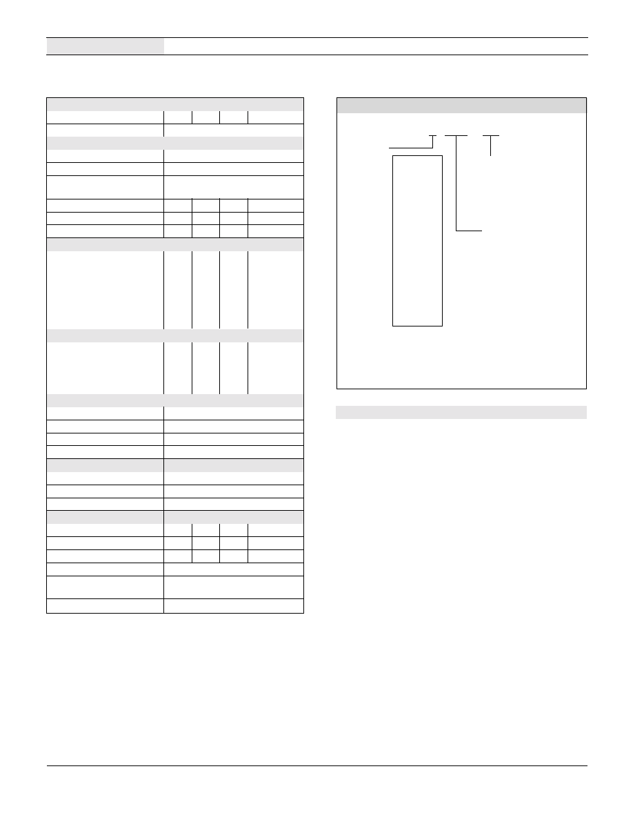
Figure 1. ACA5-20PC Series Simplified Schematic
Features
∑
Scales and displays the output of 50:5A to
2000:5A current transformers
∑
14 ranges (0-50 Amp to 0-2000 Amp)
∑
3 LED options, 6 power options, 112 models
∑
Functionally complete:
On-board 5A current transformers
Scaling/interface circuitry
Precision A/D converters
Bright red or green LED displays
∑
Subminiature, 1.38" x 0.88" package
∑
Easy-to-read, 0.37"/9.4mm digits
∑
AC powered models: 120Vac @ 400Hz,
120/220/277Vac @ 50/60Hz
∑
AC models can be "self-powered"
∑
DC powered models: +5V, +5-40V, +36-75V
∑
2000V isolation; UL/CSA recognized
∑
Digital replacements for analog ammeters
Æ
Æ
A C o r D C
I N P U T P O W E R
3 Ω D I G I T
A / D C O N V E R T E R
+ V
V
+
P R E C I S I O N
. U L L - W A V E
R E C T I . I E R
C A L .
B U I L T - I N
0 - 5 A C U R R E N T
T R A N S . O R M E R
L E D D I S P L A Y
P O W E R
C O N V E R T E R
T B 1
A
B
+
( L 1 )
O U T P U T . R O M 5 0 : 5 A
T O 2 0 0 0 : 5 A E X T E R N A L
C U R R E N T T R A N S . O R M E R
E156931
Order on-line at www.datel.com
2
DATEL, Inc., Mansfield, MA 02048 (USA)
∑
Tel: (508)339-3000, (800)233-2765 Fax: (508)339-6356
∑
E≠mail: sales@datel.com
∑
Internet: www.datel.com
ACA5-20PC Series
5 A I N P U T , 3 Ω D I G I T , L E D D I S P L A Y , A C A M M E T E R S
Performance/Functional Specifications
Typical at T
A
= + 25∞C, unless otherwise noted.
Technical Notes
IMPORTANT! To ensure safe and reliable operation, ACA5-20PC
ammeters must be installed and serviced by qualified technical
personnel. Contact DATEL if there is any doubt regarding
ammeter installation and/or operation.
1. Measurement Type: ACA5-20PC ac ammeters employ a full-wave-
rectified, average responding, rms-calibrated circuit to measure the
stepped-down output of their built-in L1 current transformer (CT) .
Stated accuracy specifications are measured using a sine-wave
current at or close to the full-scale input level, at nominal line
frequency.
2. Calibration: Periodic recalibration of ACA5-20PC ammeters is not
required under normal, indoor operating environments. If user
calibration is necessary, it should be performed by qualified technical
personnel. Calibration is performed with potentially lethal voltages
applied to the ACA5-20PC and its associated wiring, with the specified
full-scale current flowing through the ammeter's built-in current
transformer. A plastic, fully-insulated adjusting tool must be used to
access the recessed calibration potentiometer located on the back of
the meter (see Mechanical Specifications). Contact DATEL if additional
information is required regarding calibration, setup, or any other
technical issue pertaining to ACA5-20PC ammeters.
3. Wire Gauges and Fusing: Wires specified in the Functional
Specifications section must be used for making connections to ACA5-
20PC Series ammeters. All power-supply and load wiring must be
rated for the supply voltages and currents they will conduct and must
comply with any code or application-mandated requirements pertaining
to the user's specific installation.
Full-Scale Current (45-450Hz) Min.
Typ.
Max.
Units
All Models
--
--
5.0
Amps
Overcurrent Rating
1.5 x rated full-scale current
Performance
Sampling Rate
2.5 samples per second
Accuracy
±0.15%FS ±6 counts
Measurement Type
Sine wave input, full-wave
averaging, rms calibrated
Temperature Drift (0 to +60∞C)
--
±0.2
±0.4
Counts/∞C
Zero-Current Reading
-001
000
001
Counts
Dielectric Withstanding Voltage
2000
--
--
Vdc
Power Supply Voltage
ACA5-20PC-X-AC1-RL
85
120
264
Vac@47-99Hz
ACA5-20PC-X-AC2-RL
85
120
140
Vac@350-450Hz
ACA5-20PC-X-AC3-RL
240
264
310
Vac@47-99Hz
ACA5-20PC-X-DC1-RL
+4.75
--
+40
Vdc
ACA5-20PC-X-DC2-RL
+36
--
+75
Vdc
ACA5-20PC-X-DC3-XX
+4.75
--
+5.25
Vdc
Power Supply Current
ACA5-20PC-X-AC1,3-RL
--
30
50
mA@47-99Hz
ACA5-20PC-X-AC2-RL
--
30
50
mA@350-450Hz
ACA5-20PC-X-DC1,2-RL
--
+8
+12
mAdc
ACA5-20PC-X-DC3-XX
--
+80
+120
mAdc
Power Supply Terminal Block
Wire Size & Type
16-22AWG (solid or stranded)
Insulation Strip Length
0.25 inches
Screw Tightening Torque
3.6 pound-inches (0.4Nm)
Maximum Rated Voltage
310Vac
Display
Display Type and Size
3Ω digit LED, 0.37"/9.4mm digit height
Overrange Indication
"1_ _ _"
Display Reading/Decimal Point
Model dependent. See Ordering Info.
Physical/Environmental
Operating Temperature
0
--
+60
∞ C
Storage Temperature
≠40
--
+75
∞ C
Humidity (non-condensing)
0
--
95
%
Case Material
Polycarbonate
Dimensions
1.38"W x 0.88"H Depth is model
dependent (see Mechanical Specifications)
Weight (all models)
1.1 ounces (31 grams)
The specified Full-Scale Current is the current carried by the single wire passing through the
center hole of the ACA5-20PC's on-board CT. It is not the load current ultimately being
measured. the Overcurrent Rating is a continuous rating that applies to the Full-Scale
Current. It does not apply to any circuitry external to the meter.
Listed accuracy specifications apply over the range of the Rated Full-Scale Current over
frequencies of 45-450Hz.
Maximum reverse polarity protection on "DC1" models is ≠40Vdc, and ≠50Vdc on "DC2"
models. "DC3" models provide no reverse polarity protection.
All specified maximum power supply currents are steady-state. AC-powered models can
draw larger surges at initial turn on.
Ordering Information
Order on-line at www.datel.com
ACA5 - 20PC - 1 - AC1 - RL
1 = 50.0A
2 = 75.0A
3 = 100.0A
4 = 150.0A
5 = 199.9A
6 = 250A
7 = 300A
8 = 400A
9 = 500A
10 = 600A
11 = 750A
12 = 1000A
13 = 1500A
14 = 1999A
RL = Red Standard
RH = High-Intensity Red*
GS = Green Standard*
AC1 = 85-264Vac@50/60Hz
AC2 = 85-140Vac@400Hz
AC3 = 240-310Vac@50/60Hz
DC1 = +5-40Vdc
DC2 = +36-75Vdc
DC3 = +5Vdc
Input Range:
LED Color:
Power Supply:
*
Available on "DC3" +5V
powered models only
Accessories: DMS-20-CP Panel cutout punch
A DMS-BZL4 bezel assembly with sealing gasket is supplied with each ammeter.
(45-450Hz)
39-3681401*
39-3681402*
39-3681403*
39-3681404*
39-3681405*
39-3681406*
39-3681407*
39-3681408*
39-3681409*
39-3681410*
39-3681411*
39-3681412*
39-3681413*
39-3681414*
5A CT No.*
* Matching 5A Current Transformers: 5A current transformers for all ACA5-20PC
AC ammeters are available from DATEL at nominal cost. For pricing and technical
information, visit www.datel.com, select Digital Panel Meters, then Accessories.

3
DATEL, Inc., Mansfield, MA 02048 (USA)
∑
Tel: (508)339-3000, (800)233-2765 Fax: (508)339-6356
∑
E≠mail: sales@datel.com
∑
Internet: www.datel.com
5 A I N P U T , 3 Ω D I G I T , L E D D I S P L A Y , A C A M M E T E R S
ACA5-20PC Series
Step 2.
Step 3.
Step 4.
Step 1.
The supply wires connected to both the meter and the load must be
fused according to the current rating of the wire gauge being used, in
accordance with applicable regulatory codes. Also, wire insulation
should be stripped to within +/-10% of the stated dimensions, and
wires should be inserted into TB1 such that their insulation is not
pinched by the screw terminal. TB1 is to be used only for powering
the meter's internal circuitry. It must not be used to supply current
to external loads.
AC-powered models draw minimal steady-state supply currents
(50mA max.), and in most applications, they can be fused according
to the supply wire's maximum amperage rating. However, these
models can draw significantly higher surge currents for brief periods
when the ac line voltage is initially applied.
4. AC Supply Polarity and Grounding: The two supply inputs, TB1-A
and TB1-B, on all ac-powered ACA5-20PC ammeters are not in
themselves polarity sensitive, that is, they have no internal "AC LO" or
"AC HI" designations. Also, ac-powered ACA5-20PC ammeters do not
include or require a connection to earth/chassis ground.
5. Connector Torque Ratings: It is important to tighten TB1's, screw-
terminals to their rated torque specification of 3.6 pound-inches
(0.4Nm). Proper tightening will minimize connector losses and ensure
safe, reliable operation.
6. DC-Powered Models: DC-powered models draw minimal supply
currents (120mA max.) and in most applications can be fused
according to the supply wire's maximum amperage rating. However,
be sure to check and comply with all applicable codes and regulations
to ensure proper installation and operation.
7. Isolation: The on-board CT (L1) provides a minimum 2000Vdc
isolation between the current-carrying conductor passing through its
primary circuit and the ammeter supply voltage connected to TB1.
This isolation rating only applies to applications in which the load
wiring (i.e., the wire passing through L1's center hole) does not
connect directly or indirectly to TB1-A or TB1-B.
8. CT Precautions: In normal operation, a 5A current transformer's
secondary circuit operates at a very low voltage due to its closed-loop
operation and its low burden resistance. However, a CT can still
generate potentially lethal voltages if its output current is suddenly
interrupted. For example, loose CT secondary connections can cause
a condition referred to as "inductive kick". Inductive kick can generate
extremely high voltages across intermitent secondary connections.
Therefore, implementing connections to any 5A current
transformer's output leads must only be performed with zero
load-current, that is, with no power applied to the load circuit.
9. CT Connections and Grounding: Some applications require
connecting one of the external 5A CT's output leads to earth/chassis
ground. In the USA, consult the latest revision of the National
Electrical Code (NEC) for more information regarding CT grounding.
After all mechanical assembly is completed, connect the two output
leads of the external 5A CT to each other after they are run through
L1's center hole. Pressure-style connectors (commonly refered to as
"wire nuts") are acceptable as long as they are rated for the number of
conductors and voltage invloved.
10. Replacing Analog Panel Meters: ACA5-20PC ammeters can be
used as direct replacements for analog panel meters driven by 5A
CT's. All wiring operations must be performed with both the load and
the supply power sources completely de-energized.
Figure 2. Panel Installation
All connections to ACA5-20PC Series ammeters must be made
after the ammeter is securely attached to the panel and with all
load and supply voltages de-energized (off).
Care should be exercised when passing conductors through the
ammeter's built-in CT. The installed wire positions should be such that
minimal forces are applied to the built-in CT, TB1, or to the ammeter
itself. In high-vibration environments, proper strain reliefs be used for
all load and supply wiring.
To ensure a secure panel-mount installation, DATEL recommends
Panel Installation
using the DMS-BZL4 bezel assembly (with sealing gasket) supplied
with each ammeter. See Mechanical Specifications for detailed cutout
and ammeter dimensions.
Following the four-step sequence shown in Figure 2 --being careful
not to apply excessive force or twisting motions--insert the ammeter
into the panel opening. When using the DMS-BZL4, install its sealing
gasket so it is positioned between the ammeter's front flange and
panel front surface (see Mechanical Specifications). Be sure to use
and securely tighten all four screws supplied with the bezel assembly.
P A N E L
1
P A N E L
2
P A N E L
4
3
P A N E L
G A S K E T
( o p t i o n a l )
B E Z E L
4
DATEL, Inc., Mansfield, MA 02048 (USA)
∑
Tel: (508)339-3000, (800)233-2765 Fax: (508)339-6356
∑
E≠mail: sales@datel.com
∑
Internet: www.datel.com
ACA5-20PC Series
5 A I N P U T , 3 Ω D I G I T , L E D D I S P L A Y , A C A M M E T E R S
Figure 4. All ACA5-20PC DC-Powered Models
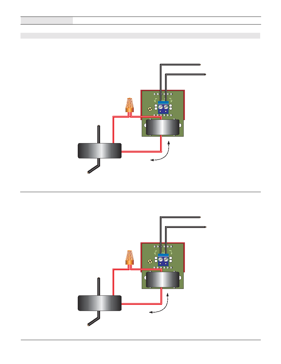
Figure 3. All ACA5-20PC AC-Powered Models
First pass and carefully dress one output wire from the external CT
through the on-board CT (L1). Then connect the ac supply to TB1 as
shown. If required, verify that correct line-power polarities are
applied to the external load (see Technical Note 4). Ensure all wires
are stripped and terminals torqued correctly. For proper operation,
pass only a single wire through the on-board CT's center hole.
Typical Wiring Diagrams
First pass and carefully dress one output wire from the external CT
through the on-board CT (L1). Then connect the two dc power-
supply wires to TB1, observing correct positive ("+") and negative
("≠") polarities. Ensure all wires are stripped and terminals torqued
correctly. For proper operation, pass only a single wire through the
on-board CT's center hole.
A C P O W E R
S U P P L Y
T B 1
A
B
E X T E R N A L
5 A - O U T P U T C U R R E N T
T R A N S . O R M E R
T O
A C L O A D
0 - 5 A
O U T P U T
A C A 5 - 2 0 P C - X - A C X
L 1
D C P O W E R
S U P P L Y
T B 1
A
B
T O
A C L O A D
0 - 5 A
O U T P U T
A C A 5 - 2 0 P C - X - D C X
L 1
+
+
E X T E R N A L
5 A - O U T P U T C U R R E N T
T R A N S . O R M E R
5 A I N P U T , 3 Ω D I G I T , L E D D I S P L A Y , A C A M M E T E R S
ACA5-20PC Series
DATEL, Inc. 11 Cabot Boulevard, Mansfield, MA 02048-1151
Tel: (508) 339-3000 (800) 233-2765 Fax: (508) 339-6356
Internet: www.datel.com Email: sales@datel.com
DATEL (UK) LTD. Tadley, England Tel: (01256)-880444
DATEL S.A.R.L. Montigny Le Bretonneux, France Tel: 01-34-60-01-01
DATEL GmbH M¸nchen, Germany Tel: 89-544334-0
DATEL KK Tokyo, Japan Tel: 3-3779-1031, Osaka Tel: 6-354-2025
DATEL makes no representation that the use of its products in the circuits described herein, or the use of other technical information contained herein, will not infringe upon existing or future patent rights. The descriptions contained herein
do not imply the granting of licenses to make, use, or sell equipment constructed in accordance therewith. Specifications are subject to change without notice. The DATEL logo is a registered DATEL, Inc. trademark.
DS-0446B 5/02
Æ
Æ
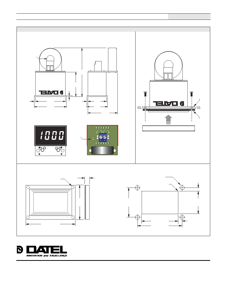
Mechanical Dimensions: Inches (mm)
Tolerances: 2 PL DEC ±0.02 (±0.51), 3 PL DEC ±0.010 (±0.254)
Mechanical Specifications
0 . 8 0
( 2 0 . 3 )
0 . 0 4 0
( 1 . 0 2 )
1 . 3 0
( 3 3 . 0 )
1 . 3 8
( 3 5 . 1 )
0 . 8 8
( 2 2 . 4 )
1 . 0 0
( 2 5 . 4 )
1 . 3 2
( 3 3 . 5 )
0 . 0 4 0
( 1 . 0 2 )
0 . 0 4 0
( 1 . 0 2 )
2 . 0 1
( 5 1 . 1 )
T B 1
A
B
C A L .
Æ
Æ
. R O N T V I E W
B A C K V I E W
H o l e D i a m e t e r :
0 . 2 7 ( 6 . 9 ) m i n .
B E Z E L I N S T A L L A T I O N
B E Z E L
P A N E L
G A S K E T
( o p t i o n a l )
Æ
Æ
# 2 - 5 6 I N S E R T
0 . 1 5 6 ( 3 . 9 6 ) D E E P
. R O N T V I E W
1 . 2 8 0
( 3 2 . 5 1 )
0 . 1 8 7
( 4 . 7 5 )
D M S - B Z L 4 B E Z E L
1 . 8 2 6 ( 4 6 . 3 8 )
R E C O M M E N D E D D R I L L A N D P A N E L C U T O U T D I M E N S I O N S
0 . 8 3 8
( 2 1 . 2 9 )
1 . 6 2 6 ( 4 1 . 3 0 )
1 . 0 7
( 2 7 . 1 8 )
I N T E R N A L C O R N E R R A D I I :
0 . 0 3 2 ( 0 . 8 1 ) M A X .
0 . 0 9 3 ( 2 . 3 6 2 ) D I A M E T E R ( 4 R E Q U I R E D ) O N L Y
W H E N U S I N G S U P P L I E D B E Z E L A S S E M B L Y
0 . 1 1 6
( 2 . 9 5 )
1 . 3 3 6 ( 3 3 . 9 3 )
0 . 1 4 5 ( 3 . 6 8 )
ISO 9001
R E G I S T E R E D