5V and 3.3V, "Half-Brick"
75 Watt, DC/DC Converters
Dual Output
Mixed Voltage, BCP Models
Features
As your new, mixed-logic (5V and 3.3V) design evolves and your current require-
ments change, your new DC/DC converter will not. DATEL's BCP-5/15-3.3/15-D24
(18-36V input) and BCP-5/15-3.3/15-D48 (36-75V input) are fully isolated DC/DC
converters providing both 5V and 3.3V outputs. Housed in standard "half-brick"
packages (2.3" x 2.4" x 0.525"), the BCP's can support any combination of 5V and
3.3V loading up to a combined total of 15 Amps. Both outputs are fully isolated
(1500Vdc) and independently line (±0.2%) and load (±0.5% and ±0.6%) regulated.
Both BCP models feature input pi fi lters, input undervoltage and overvoltage
shutdown, input reverse-polarity protection, output overvoltage protection, current
limiting, and thermal shutdown. Each has an on/off control function, and the two
output voltages can be trimmed independently.
BCP Model DC/DC's deliver low noise (50mVp-p), high effi ciency (87%) and are
fully specifi ed for ≠40 to +100∞C operation. Utilization of metal baseplate technology
with threaded inserts permits easy heat-sink attachment and/or pcb mounting. These
devices meet IEC950, UL1950, EN60950 and VDE safety standards, including
BASIC insulation requirements. CB reports are available on request. "D48" models
are CE marked (meet the requirements of LVD).
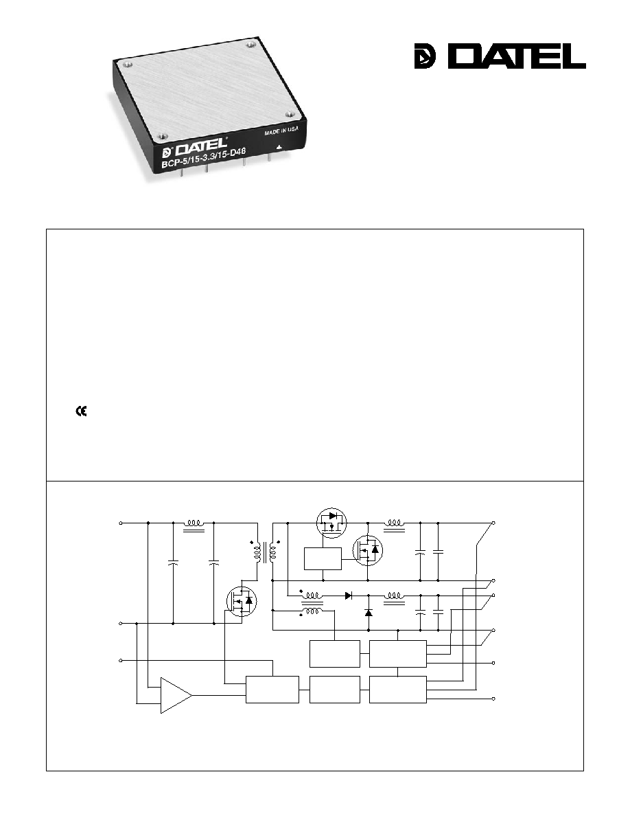
Figure 1. Simplifi ed Schematic
INNOVATION and EX C ELL E N C E
Æ
Æ
Independent 5V and 3.3V outputs
Each output fully regulated
No minimum load requirements
Up to 15 Amps per output
75 Watts total output power
Standard "half-brick" package
UL1950, EN60950 and VDE safety
approvals (BASIC insulation)
Fully isolated, 1500Vdc guaranteed
18-36V or 36-75V input ranges
mark available (75V-input models)
Input under and overvoltage shutdown
Continuous short-circuit protection
Thermal shutdown
+INPUT
(4)
≠INPUT
(1)
SWITCH
CONTROL
+5V OUTPUT
(7)
+3.3V OUTPUT
(10)
5V RETURN (6)
3.3V RETURN
(9)
3.3V TRIM
(8)
5V TRIM
(5)
MAG AMP
CONTROLLER
PWM
CONTROLLER
REFERENCE &
ERROR AMP
OPTO
ISOLATION
ON/OFF
CONTROL
(3)
UV & OV
COMPARATORS
REFERENCE &
ERROR AMP
DATEL, Inc., Mansfi eld, MA 02048 (USA) ∑ Tel: (508)339-3000, (800)233-2765 Fax: (508)339-6356 ∑ Email: sales@datel.com ∑ Internet: www.datel.com
7 5 W , D U A L O U T P U T , M I X E D - V O L T A G E D C / D C C O N V E R T E R S
XCP Series
Performance Specifi cations and Ordering Guide
V
1
Nominal Output Voltage: 5 Volts
5
BCP
15
-
/
D24
-
Input Voltage Range:
D24 = 18-36 Volts (24V nominal)
D48 = 36-75 Volts (48V nominal)
I
1
Maximum Output Current: 15A
Dual Output/
Standard Half-Brick Package
P A R T N U M B E R S T R U C T U R E
3.3 15
/
-
N
V
2
Nominal Output Voltage: 3.3 Volts
I
2
Maximum Output Current: 15A
Optional Functions
Blank
On/Off Control function (positive polarity) on pin 3
N
On/Off Control function (negative polarity) on pin 3
L1
Pin length: 0.110 in. (2.79mm) ±0.010
L2
Pin length: 0.145 in. (3.68mm) ±0.010
Refer to last page for additional options
BCP-5/15-3.3/15-D24
5 15 50 100 ±0.2% ±0.5%
24 18-36 215/3720 84% 87.2% C19, P29
3.3 15 50 100 ±0.2% ±0.6%
BCP-5/15-3.3/15-D48
5 15 50 100 ±0.2% ±0.5%
48 36-75 125/1860 84% 88% C19, P29
3.3 15 50 100 ±0.2% ±0.6%
Typical at T
A
= +25∞C under nominal line voltage and balanced "full-load" (5V @7.5A, 3.3V @ 7.5A)
conditions unless otherwise noted.
Ripple/Noise (R/N) measured over a 20MHz bandwidth. All models are specifi ed with 22µF, low-ESR,
input capacitor and 10µF tantalum in parallel with 1µF ceramic output capacitors.
Output
Input
No load to 100% load, other output at no-load.
Nominal line voltage, no-load/5V at full-load condition.
Current from either output at maximum value, or both outputs to a combined total of 15 A.
5V at full-load condition.
R/N (mVp-p)
Regulation (Max.)
Effi ciency
Package
V
OUT
I
OUT
V
IN
Nom.
Range
I
IN
(Case,
Model
(Volts)
(Amps) Typ.
Max. Line
Load
(Volts) (Volts) (mA) Min. Typ. Pinout)
Pin Function
P29 Pin Function
P29
1
≠Input
6
5V
Return
2 Case
(Baseplate) 7
+5V
Output
3 On/Off
Control
8
3.3V
Trim
4
+Input
9
3.3V
Return
5
5V
Trim
10
+3.3V
Output
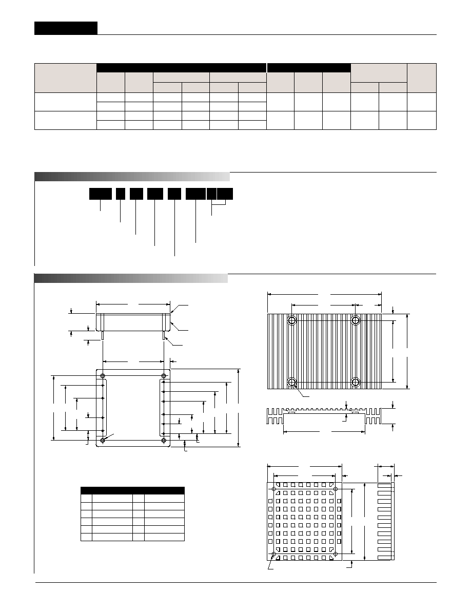
M E C H A N I C A L S P E C I F I C A T I O N S
Optional Heat Sink (Part Number HS-CPLP2)
0.30
(7.62)
0.400
(10.16)
1.000
(25.40)
1.400
(35.56)
2.40
(60.96)
1.000
(25.40)
1.900
(48.26)
2.30
(58.42)
1
2
3
4
9
10
8
7
6
5
2.000
(50.80)
(4) THREADED INSERTS
#M3 THD THRU
0.20
(5.08)
0.20
(5.08)
0.200
(5.08)
BOTTOM VIEW
0.300
(7.62)
0.600
(15.24)
1.300
(33.02)
1.600
(40.64)
METAL BASEPLATE
PLASTIC SHELL
0.20 MIN
(5.08)
0.545 (13.84) MAX.
0.525 (13.34) TYP.
0.040 ±0.002 DIA.
(1.016 ±0.051)
DIMENSIONS ARE IN INCHES (MM)
Case C19
I/O Connections
2.000
(50.80)
2.30
(58.42)
1.900
(48.26)
2.40
(60.96)
0.20
(5.08)
0.147 DIA. (3.734)
(4 PLACES)
0.20
(5.08)
0.50 (12.70) TYP.
051 (12.95) MAX.
0.10
(2.54)
TOP VIEW
MATERIAL: BLACK ANODIZED ALUMINUM
4 MOUNTING SCREWS AND 0.009 (0.229)
THICK THERMAL PAD INCLUDED
3.50
(88.90)
0.75
(19.05)
0.20
(5.08)
0.140 THRU AND COUNTERSINK
90∞ TO 0.26 (4 PLACES)
2.000
(50.80)
1.900
(48.26)
2.30
(58.42)
0.47
(11.94)
MATERIAL: BLACK ANODIZED ALUMINUM
2.48
(62.99)
0.16
(4.06)
Optional Heat Sink (Part Number HS-CP)
2
LX
Optional Functions:
See also last page
BCP Models
7 5 W , D U A L O U T P U T , M I X E D - V O L T A G E D C / D C C O N V E R T E R S
Performance/Functional Specifi cations
Typical @ T
A
= +25∞C under nominal line voltage, balanced "full-load" conditions, unless noted.
Input
Input Voltage Range:
D24 Models 18-36 Volts (24V nominal)
D48 Models 36-75 Volts (48V nominal)
Overvoltage Shutdown:
D24 Models 37.5-40.5 Volts (39V typical)
D48 Models 78.8-87.0 Volts (83V typical)
Start-Up Threshold:
D24 Models 15.5-18 Volts (16.5V typical)
D48 Models 33.5-36 Volts (34.4V typical)
Undervoltage Shutdown:
D24 Models 14-16 Volts (15.3V typical)
D48 Models 30.5-33.5 Volts (31.8V typical)
Input Current:
Normal Operating Conditions See Ordering Guide
Minimum Input Voltage:
D24 Models 5.02 Amps maximum
D48 Models 2.51 Amps maximum
Standby Mode:
Off, OV, UV, Thermal Shutdown 17mA typical
Input Refl ected Ripple Current:
Source Impedance <0.1
22µF Low-ESR Capacitor 53mArms, 150mAp-p maximum
Input Filter Type Pi (0.47pF - 4.7µH - 3µF)
Reverse-Polarity Protection:
D24 Models 1 minute duration, 6A maximum
D48 Models 1 minute duration, 4A maximum
On/Off Control: (Pin 3)
D24 & D48 Models On = open or 2.0 - +V
IN
, I
IN
= 50µA max.
Off = 0-0.6V, I
IN
= 1mA max.
D24N & D48N" Models On = 0-0.6V, I
IN
= 1mA max.
Off = open or 2.0 - +V
IN
, I
IN
= 50µA max.
Output
V
OUT
Accuracy
5V Output ±2% maximum
3.3V Output ±2% maximum
Minimum Loading Per Specifi cation No load
Ripple/Noise (20MHz BW)
See Ordering Guide
Line/Load Regulation See Ordering Guide
Effi ciency See Ordering Guide and Effi ciency Curves
Trim Range
±10% independent
Isolation Voltage:
Input-to-Output 1500Vdc minimum
Input-to-Case 1000Vdc minimum
Output-to-Case 1000Vdc minimum
Isolation Capacitance 470pF
Isolation resistance 100M
Current Limit Inception:
5V @ 98% V
OUT
(3.3V no-load) 16-20 Amps
3.3V @ 98% V
OUT
(5V no-load) 16-20 Amps
Short Circuit Current:
Constant current 25A, indefi nite
Temperature Coeffi cient ±0.02% per ∞C
Overvoltage Protection:
Magnetic feedback, latching
5V Output 6.8 volts
3.3V Output 4.5Volts
Dynamic Characteristics
Dynamic Load Response:
5V (50-100% load step to 1% V
OUT
) 450µsec maximum
3.3V (50-100% load step to 1% V
OUT
) 450µsec maximum
Start-Up Time:
V
IN
to V
OUT
30msec maximum
On/Off to V
OUT
20msec maximum
Switching Frequency 350kHz (±35kHz)
Environmental
MTBF Bellcore, ground fi xed, controlled
D24 Models 1.49M hours (case @ 50∞C)
D48 Models 1.72M hours (case @ 50∞C)
Operating Temperature (Ambient):
Case to Ambient, No Heatsink 6.8∞C/Watt
Without Derating ≠40 to +45∞C (with heat sink)
With Derating To +100∞C (See Derating Curves)
Case Temperature:
Maximum Allowable +100∞C
For Thermal Shutdown
+100∞C minimum, +110∞C maximum
Storage Temperature ≠40 to +120∞C
Physical
Dimensions 2.3" x 2.4" x 0.525" (58.4 x 61 x 13.3mm)
Case (Baseplate) Connection
Pin 2
Case/Pin Material Diallyl phthalate, UL94V-0 rated, aluminum
baseplate; solder-tinned brass pins
Weight 4.2 ounces (118 grams)
Primary to Secondary Insulation Level Basic
Absolute Maximum Ratings
Models are specifi ed at "full load" (5V & 3.3V @ 7.5A), with an external 22µF, low-ESR,
input capacitor and 10µF tantalum in parallel with 1µF ceramic output capacitors.
See Technical Notes for details.
Devices may be ordered with opposite polarity (pin 3 open = off). See Part Number
Suffi xes and Technical Notes for additional information.
Output noise may be further reduced with the installation of additional external output
capacitors. See Technical Notes.
These signals must be referenced to the input return pin (≠V
IN
).
Demonstrated MTBF available on request.
Input Voltage:
Continuous:
D24 Models 40.5 Volts
D48 Models 87 Volts
Transient (100msec): D24 Models 50 Volts
D48 Models 100 Volts
Input Reverse-Polarity Protection
Input Current must be limited. 1 minute
duration. Fusing recommended.
D24 Models
6 Amps
D48 Models
4 Amps
Output Overvoltage Protection
3.3V Outputs
3.8 Volts, latching
5V Outputs
6.2 Volts, latching
Output Current
Current limited. Devices can withstand
an indefi nite output short circuit.
Storage Temperature
≠40 to +120∞C
Lead Temperature (Soldering, 10 sec.) +300∞C
These are stress ratings. Exposure of devices to any of these conditions may adversely
affect long-term reliability. Proper operation under conditions other than those listed in the
Performance/Functional Specifi cations Table is not implied, nor recommended.
3

7 5 W , D U A L O U T P U T , M I X E D - V O L T A G E D C / D C C O N V E R T E R S
XCP Series
5V & 3.3V Outputs/Returns
The BCP Series outputs (pins 7 & 10) and returns (pins 6 & 9) are isolated
from the +V
IN
and ≠V
IN
inputs (pins 4 & 1) via a transformer and opto-coupled
transistors.
The +5V Return (pin 6) and +3.3V Return (pin 9) are connected internal
to the DC/DC converter. Though the returns are common within the DC/DC
converter, the regulating control loop for each output is sensed directly at its
respective output and return pins. In order to maintain optimum regulation if
ground plane is not used, it is critical that PC board layouts also return each
output to its corresponding return pin.
Filtering and Noise Reduction
All BCP DC/DC Converters achieve their rated ripple and noise specifi cations
using the external input and output capacitors specifi ed in the Performance/
Functional Specifi cations table. In critical applications, input/output noise may
be further reduced by installing additional external I/O caps. Input capacitors
should be selected for bulk capacitance, low ESR and high rms-ripple-current
ratings. Output capacitors should be selected for low ESR and appropriate
frequency response. All caps should have appropriate voltage ratings and be
mounted as close to the converters as possible.
The most effective combination of external I/O capacitors will be a function of
your particular load and layout conditions. Our Applications Engineers will be
pleased to recommend potential solutions and can discuss the possibility of
our modifying a device's internal fi ltering to meet your specifi c requirements.
Contact our Applications Engineering Group for additional details.
Input Fusing
Certain applications and/or safety agencies may require the installation of
fuses at the inputs of power conversion components. Fuses should also be
used if the possibility of sustained, non-current-limited, input-voltage polarity
reversals exists. For DATEL BCP DC/DC Converters, you should use slow-
blow type fuses with values no greater than the following.
V
IN
Range Fuse Value
"D24" Models 6 Amps
"D48" Models 4 Amps
Fuses should be installed in the +Input line.
Input Overvoltage/Undervoltage Shutdown and Start-Up Threshold
Under normal start-up conditions, devices will not begin to regulate until
the ramping-up input voltage exceeds the Start-Up Threshold Voltage (35V
for "D48" models). Once operating, devices will not turn off until the input
voltage drops below the Undervoltage Shutdown limit (32V for "D48" models).
Subsequent re-start will not occur until the input is brought back up to the
Start-Up Threshold. This built-in hysteresis prevents any unstable on/off
situations from occurring at a single voltage.
Input voltages exceeding the input overvoltage shutdown specifi cation listed
in the Performance/Functional Specifi cations will cause the device to shut-
down. A built-in hysteresis (2V typical for "D24" models, 4V typical for
"D48" models) will not allow the converter to restart until the input voltage
is suffi ciently reduced.
Start-Up Time
The V
IN
to V
OUT
start-up time is the interval between the time at which
a ramping input voltage crosses the turn-on threshold point and the fully-
loaded output voltage enters and remains within its specifi ed accuracy band.
Actual measured times will vary with input source impedance, external input
capacitance, and the slew rate and fi nal value of the input voltage as it
appears to the converter.
The On/Off to V
OUT
start-up time assumes the converter has its nominal input
voltage applied but is turned off via the On/Off Control. The specifi cation
defi nes the interval between the time at which the converter is turned on
and the fully loaded output voltage enters and remains within its specifi ed
accuracy band.
On/Off Control (Standard feature)
The On/Off Control (pin 3) may be used for remote on/off operation. As shown
in Figure 1A, the control pin is referenced to the ≠Input (pin 1) and will be
pulled to a high state internally. The standard BCP converter (no suffi x) is
designed so that it is enabled when the control pin is left open and disabled
when the control pin is pulled low (to less than +0.6V relative to ≠Input).
Dynamic control of the on/off function is best accomplished with a mechanical
relay or an open-collector/open-drain drive circuit (optically isolated if
appropriate). The drive circuit should be able to sink approximately 1mA for
logic low.
The on/off control function is designed such that the converter can be dis-
abled (pin 3 pulled low for no-suffi x models) while input power is ramping up
and then "released" once the input has stabilized.
For BCP converters confi gured with the negative-polarity option on the On/Off
Control pin ("N" suffi x added to part number), operation is opposite to that
described above. The converter is disabled when the On/Off Control pin is left
open and enabled when pulled low.
T E C H N I C A L N O T E S
Figure 1A. No Suffi x
Figure 1B. "N" Suffi x
3
1
4
100k
+INPUT
≠INPUT
ON/OFF
CONTROL
3
1
4
21k
3.3V
+INPUT
≠INPUT
ON/OFF
CONTROL
4
BCP Models
7 5 W , D U A L O U T P U T , M I X E D - V O L T A G E D C / D C C O N V E R T E R S
Output Overvoltage Protection
Each voltage output of the BCP Series converter is independently monitored
via an auxiliary winding in the output inductor. If the output voltage
should rise to a level which could be damaging to the load circuitry (see
Performance/Functional Specifi cations for limits), the overvoltage circuitry will
power down the PWM controller and latch off the DC/DC converter. The
device must now be restarted by powering cycling V
IN
.
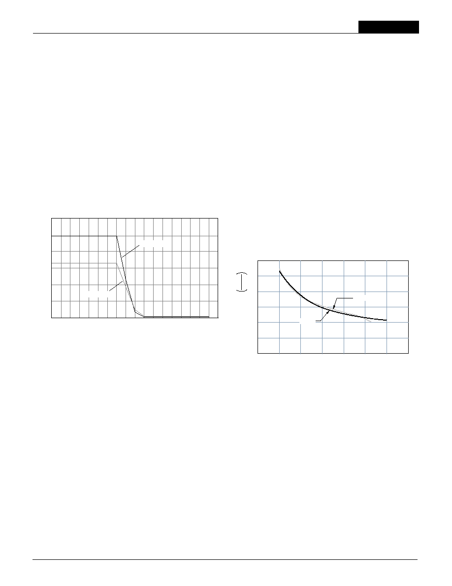
Current Limiting
When output current demands exceed the maximum output current rating by
107% to 133%, the DC/DC converter will go into a current limiting mode.
In this condition the output voltage decreases proportionately as the output
current increases, thereby maintaining a somewhat constant power dissipa-
tion--referred to as Power Limiting (see Figure 2). As the load approaches a
short circuit, the output current will continue to increase until it reaches the
rated Short Circuit Current limit.
Short Circuit Condition
As described under "Current Limiting," when the BCP Series DC/DC con-
verter output is subjected to a short circuit condition, the output current will
remain at the Short Circuit Current limit. In this state there is negligible power
dissipated in the load. Therefore, most of the input power is dissipated within
the converter, causing the internal temperature to increase. If this condition
persists, Thermal Shutdown will activate and shutdown the DC/DC converter.
When the internal temperature is suffi ciently decreased, the converter will
self-start.
Thermal Shutdown
The BCP Series is equipped with Thermal Shutdown circuitry. If the internal
temperature of the DC/DC converter rises above the designed operating
temperature, a precision temperature sensor will power down the unit. When
the internal temperature decreases below the threshold of the temperature
sensor the unit will self-start.
BCP-5/15-3.3/15-D24, D48 Current Limiting Characteristics
(Nominal V
IN
)
Output V
olta
g
e
V
OUT
(V
olts)
Output Current, I
OUT
(Amps)
6.00
5.00
4.00
3.00
2.00
1.00
0
5V Output
3.3V Output
15.2
15.7
16.2
16.7
17.2
17.8
18.3
18.8
19.3
19.8
20.3
20.9
21.9
22.4
22.6
23.5
24
25
26
Figure 2. Current Limiting Characteristics
Input Reverse-Polarity Protection
Upon applying a reverse-polarity voltage to the DC/DC converter, an internal
diode will be forward biased and draw excessive current from the power
source. Therefore, it is required that the input current be limited be either an
appropriately rated input fuse or a current limited power source.
Heat Sinks for BCP Series
DATEL offers two standard heat sinks that can be mounted to the half-brick
package to extend the converter's operating temperature range. Along with
the standard 2.3" x 2.4" x 0.5" (HS-CP) heat sink, DATEL has designed
a low-profi le heat sink for height-restricted applications. This new heat sink
(HS-CPLP2) is designed with radiant fi ns that extend 0.51" beyond either
side of the 2.4" dimension of the BCP package. The convenience of this
design is that the fi nned extensions protrude only 0.31" below the top surface
of the DC/DC converter, allowing components with a profi le height less than
0.215" to be mounted on the pc board below the heat sink. Therefore, while
the surface area of the low-profi le heat sink measures 2.3" x 3.5", pcb real
estate is unaffected.
For optimum thermal performance in a natural convection application, the
low-profi le heat sink should be mounted with the fi ns vertically oriented. Both
models are shipped with 0.009" sellf-adhesive thermal pad and mounting
screws.
6
5
4
3
2
1
0
0
100
200
300
400
500
600
700
AIR VELOCITY (FT./MIN.)
HS-CP
THERMAL RESIST
ANCE
∞
C
WA
T
T
HS-CPLP2
HS-CP and HS-CPLP2 Heat Sink Performance Vs. Air Flow
(@ 10.5 Watts Power Dissipation)
5
7 5 W , D U A L O U T P U T , M I X E D - V O L T A G E D C / D C C O N V E R T E R S
XCP Series
V
O
= 5.0 +
V
O
= 1.25
≠4.99
≠4.99
1
0.30R
T
(k
) + 1.5
UP
R
T
(k
) + 4.99
DOWN
DOWN
UP
V
O
= 3.30 +
1
R
T
(k
) + 2.37
UP
1
(0.3V
O
) ≠ 1.50
(0.8V
O
) ≠ 1
R
T
(k
) =
R
T
(k
) =
≠2.37
≠0.38
UP
1
V
O
≠ 3.3
1.14
1.14
+1
0.38 +
1
R
T
(k
) =
V
O
= 1.23
R
T
(k
)+ 2.37
DOWN
2.07
+1
1.23 +
1
1
≠2.37
DOWN
V
O
R
T
(k
) =
≠1.23
1.23
2.07
1
≠1
+3.3V
LOAD
+3.3V OUTPUT
≠INPUT
+INPUT
3.3V TRIM
3.3V RETURN
+5V OUTPUT
5V TRIM
5V RETURN
10
8
1
4
9
7
5
6
20k
5-22
TURNS
+5V
LOAD
20k
5-22
TURNS
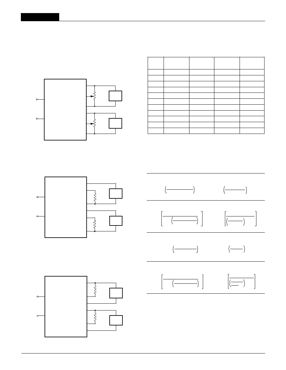
Output Trimming
Both the 5V and 3.3V outputs of the BCP Series can be independently
trimmed via a trimpot (Figure 3A) or a single fi xed resistor as shown (Figures
3B & 3C). The trimpot can be used to determine the value of a single fi xed
resistor. A single fi xed resistor can increase or decrease the output voltage
depending on its connection. Fixed resistors should be metal-fi lm types with
absolute TCR's less than 100ppm/∞C to ensure stability.
Case Connection
BCP DC/DC's do not have their metal baseplate connected to one of the input
pins. The "uncommitted" baseplate is connected to pin 2 which, depending
upon your system confi guration, should be connected to either +Input (pin 4),
≠Input (pin 1), Output Returns (pins 6 & 9), or earth ground.
+3.3V
LOAD
+3.3V OUTPUT
≠INPUT
+INPUT
3.3V TRIM
3.3V RETURN
+5V OUTPUT
5V TRIM
5V RETURN
10
8
1
4
9
7
5
6
+5V
LOAD
+5V
TRIM
DOWN
+3.3V
TRIM
DOWN
Figure 3A. Trim Connections Using a Trimpot
Figure 3B. Increase Output Voltage Trim Connections Using a Fixed Resistor
A resistor connected from the Trim Pin (pin 5 for 5V trim, pin 8 for 3.3V trim)
to the appropriate Return (pin 6 for 5V trim, pin 9 for 3.3V trim) will increase
the output voltage.
A single resistor connected from the Trim Pin (pin 5 for 5V trim, pin 8 for
3.3V trim) to its appropriate +Output (pin 7 for 5V trim, pin 10 for 3.3V trim)
will decrease the output voltage.
+3.3V
LOAD
+3.3V OUTPUT
≠INPUT
+INPUT
3.3V TRIM
3.3V RETURN
+5V OUTPUT
5V TRIM
5V RETURN
10
8
1
4
9
7
5
6
+5V
LOAD
+5V
TRIM
UP
+3.3V
TRIM
UP
Figure 3C. Decrease Output Voltage Trim Connections Using a Fixed Resistor
Table 1 shows the typical fi xed Trim Resistor values for output voltage
changes of 0 through 10%. Trim adjustment greater than 10% can have an
adverse affect on the converter's performance and is not recommended.
Table 1. Percentage of Output Voltage Change vs Trim Resistor Value (Ohms)
3.3V 3.3V 5V 5V
Trim Down Trim Up Trim Down Trim Up
0% ≠ ≠ ≠ ≠
1% 47.81k 27.93k 189.75k 61.68k
2% 22.32k 12.78k 91.06k 28.34k
3% 13.82k 7.73k 58.17k 17.23k
4% 9.57k 5.21k 41.72k 11.68k
5% 7.02k 3.69k 31.85k 8.34k
6% 5.320k 2.68k 25.27k 6.12k
7% 4.10k 1.96k 20.57k 4.53k
8% 3.19k 1.42k 17.05k 3.34k
9% 2.48k 1.00k 14.31k 2.42k
10% 1.92k 0.66k 12.12k 1.68k
The following equations mathematically depict:
Output Voltage for a given Trim Resistor
Trim Resistor for a given Output Voltage
5 Volt Trim Up
5 Volt Trim Down
3.3 Volt Trim Up
3.3 Volt Trim Down
6
Note: Resistor values are in k
. Accuracy of adjustment is subject
to tolerances of resistor values and factory-adjusted output accuracy.
V
O
= desired output voltage.

BCP Models
7 5 W , D U A L O U T P U T , M I X E D - V O L T A G E D C / D C C O N V E R T E R S
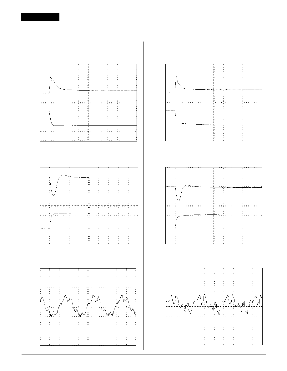
5V Output Half-Load to Full-Load Transient Response
(V
IN
= 24V, 3.3V@ 0A, external 10µF || 1µF output capacitors.)
5V Output
100mV/div
15A
7.5A
Output
Current
5A/div
100µsec/div
5V Output Half-Load to Full-Load Transient Response
(V
IN
= 48V, 3.3V@ 0A, external 10µF || 1µF output capacitors.)
15A
7.5A
5V Output
100mV/div
Output
Current
5A/div
100µsec/div
5V Output Full-Load to Half-Load Transient Response
(V
IN
= 24V, 3.3V@ 0A, external 10µF || 1µF output capacitors.)
5V Output
100mV/div
15A
7.5A
Output
Current
5A/div
100µsec/div
Output Ripple and Noise (PARD)
(
V
IN
= 48V, 5V@7.5A, 3.3V @ 7.5A, external 10µF || 1µF output capacitors.)
3.3V Output
Ripple/Noise
20mV/div
5V Output
Ripple/Noise
20mV/div
1µsec/div
Output Ripple and Noise (PARD)
(
V
IN
= 24V, 5V@7.5A, 3.3V @ 7.5A, external 10µF || 1µF output capacitors.)
3.3V Output
Ripple/Noise
20mV/div
5V Output
Ripple/Noise
20mV/div
1µsec/div
5V Output Full-Load to Half-Load Transient Response
(V
IN
= 48V, 3.3V@ 0A, external 10µF || 1µF output capacitors.)
15A
7.5A
5V Output
100mV/div
Output
Current
5A/div
100µsec/div
D24 Model
D48 Model
Typical Performance Curves
7
7 5 W , D U A L O U T P U T , M I X E D - V O L T A G E D C / D C C O N V E R T E R S
XCP Series
3.3V Output Full-Load to Half-Load Transient Response
(V
IN
= 24V, 5V@ 0A, external 10µF || 1µF output capacitors.)
15A
3.3V Output
100mV/div
Output
Current
5A/div
100µsec/div
7.5A
3.3V Output Full-Load to Half-Load Transient Response
(V
IN
= 48V, 5V@ 0A, external 10µF || 1µF output capacitors.)
3.3V Output
100mV/div
Output
Current
5A/div
100µsec/div
15A
7.5A
3.3V Output Half-Load to Full-Load Transient Response
(V
IN
= 24V, 5V@ 0A, external 10µF || 1µF output capacitors.)
3.3V Output
200mV/div
15A
Output
Current
5A/div
100µsec/div
7.5A
3.3V Output Half-Load to Full-Load Transient Response
(V
IN
= 48V, 5V@ 0A, external 10µF || 1µF output capacitors.)
15A
7.5A
3.3V Output
200mV/div
Output
Current
5A/div
100µsec/div
Input Ripple Current
(V
IN
= 24V, 5V @ 15A, 3.3V@ 0A, external 22µF low-ESR input capacitor.)
50mA/div
1µsec/div
Input Ripple Current
(V
IN
= 48V, 5V @ 15A, 3.3V@ 0A, external 22µF low-ESR input capacitor.)
50mA/div
1µsec/div
D24 Model
D48 Model
Typical Performance Curves
8
BCP Models
7 5 W , D U A L O U T P U T , M I X E D - V O L T A G E D C / D C C O N V E R T E R S
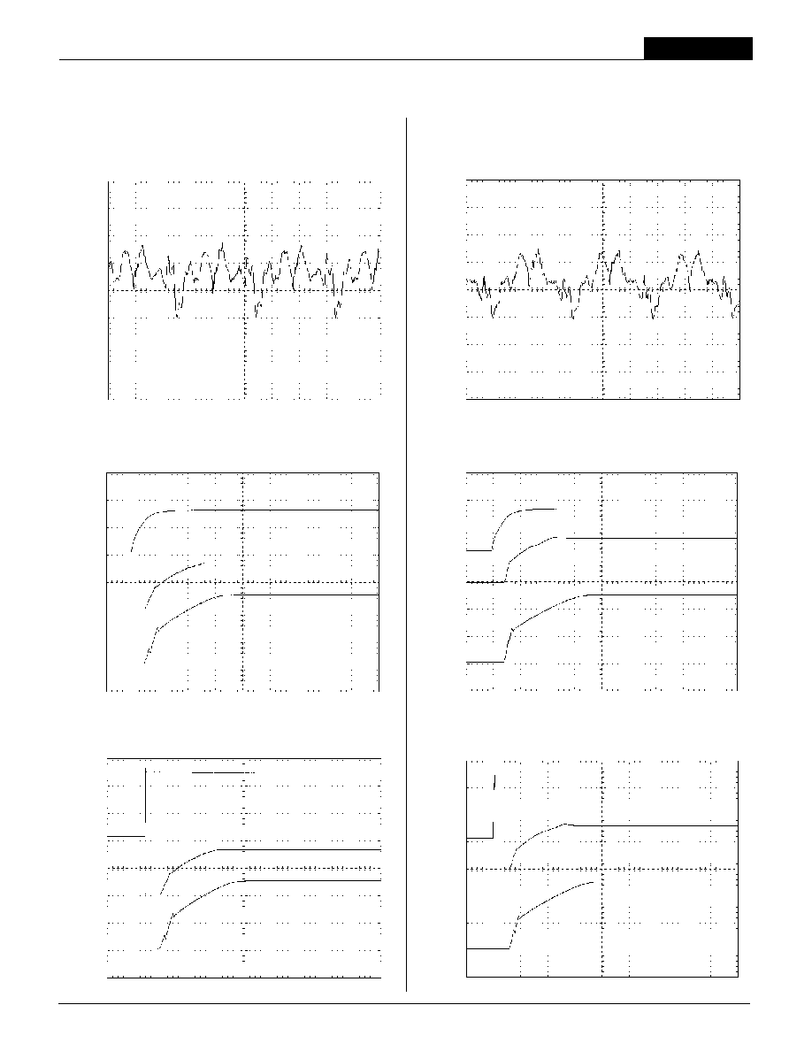
Input Ripple Current
(V
IN
= 24V, 5V @ 0A, 3.3V @ 15A, external 22µF low-ESR input capacitor.)
50mA/div
1µsec/div
Input Ripple Current
(V
IN
= 48V, 5V @ 0A, 3.3V @ 15A, external 22µF low-ESR input capacitor.)
50mA/div
1µsec/div
Start-Up from Remote On/Off Control
(V
IN
= 24V, 5V@ 7.5A, 3.3V @ 7.5A, external 10µF || 1µF output capacitors.)
4msec/div
Remote
On/Off
(Pin 3)
2V/div
3.3V
Output
2V/div
5V
Output
2V/div
Start-Up from Remote On/Off Control
(V
IN
= 48V, 5V@ 7.5A, 3.3V @ 7.5A, external 10µF || 1µF output capacitors.)
Remote
On/Off
(Pin 3)
2V/div
3.3V
Output
2V/div
5V
Output
2V/div
4msec/div
V
IN
10V/div
3.3V
Output
2V/div
5V
Output
2V/div
Start-Up from V
IN
(V
IN
= 24V, 5V@ 7.5A, 3.3V @ 7.5A, external 10µF || 1µF output capacitors.)
4msec/div
V
IN
20V/div
3.3V
Output
2V/div
5V
Output
2V/div
Start-Up from V
IN
(V
IN
= 48V, 5V@ 7.5A, 3.3V @ 7.5A, external 10µF || 1µF output capacitors.)
4msec/div
D24 Model
D48 Model
Typical Performance Curves
9
7 5 W , D U A L O U T P U T , M I X E D - V O L T A G E D C / D C C O N V E R T E R S
XCP Series
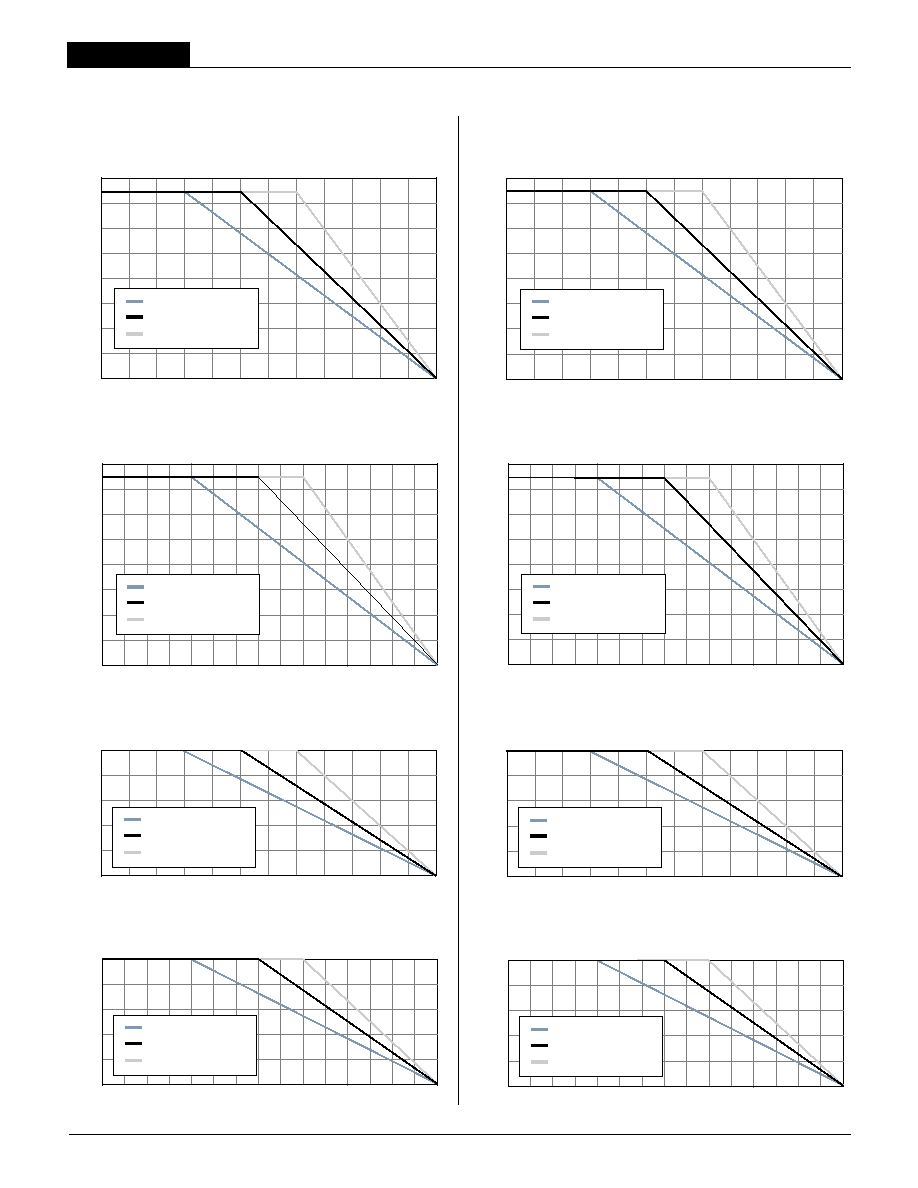
Output P
o
wer (W
atts)
Ambient Temperature (
∞C)
Output Power vs. Ambient Temperature
(Without heat sink, 5V Output, 3.3V @ 0A.)
80
70
60
50
40
30
20
10
0
≠40
≠10
0
10
20
30
40
50
60
70
80
90
100
Natural Convection Cooling
150 Linear Feet Per Minute
300 Linear Feet Per Minute
Output Power vs. Ambient Temperature
(With HS-CP heat sink, 5V Output, 3.3V @ 0A.)
Output P
o
wer (W
atts)
Ambient Temperature (
∞C)
80
70
60
50
40
30
20
10
0
≠40
0
35
40
45
50
55
60
65
70
75
80
85
90
95
100
Natural Convection Cooling
150 Linear Feet Per Minute
300 Linear Feet Per Minute
Output P
o
wer (W
atts)
Ambient Temperature (
∞C)
Output Power vs. Ambient Temperature
(Without heat sink, 5V Output, 3.3V @ 0A.)
80
70
60
50
40
30
20
10
0
≠40
≠10
0
10
20
30
40
50
60
70
80
90
100
Natural Convection Cooling
150 Linear Feet Per Minute
300 Linear Feet Per Minute
Output Power vs. Ambient Temperature
(With HS-CP heat sink, 5V Output, 3.3V @ 0A.)
Output P
o
wer (W
atts)
Ambient Temperature (
∞C)
80
70
60
50
40
30
20
10
0
≠40
0
35
40
45
50
55
60
65
70
75
80
85
90
95
100
Natural Convection Cooling
150 Linear Feet Per Minute
300 Linear Feet Per Minute
Output P
o
wer (W
atts)
Ambient Temperature (
∞C)
50
40
30
20
10
0
≠40
≠10
0
10
20
30
40
50
60
70
80
90
100
Output Power vs. Ambient Temperature
(Without heat sink, 3.3V Output, 5V @ 0A.)
Natural Convection Cooling
150 Linear Feet Per Minute
300 Linear Feet Per Minute
Output P
o
wer (W
atts)
Ambient Temperature (
∞C)
50
40
30
20
10
0
≠40
0
35
40
45
50
55
60
65
70
75
80
85
90
95
100
Output Power vs. Ambient Temperature
(With HS-CP heat sink, 3.3V Output, 5V @ 0A.)
Natural Convection Cooling
150 Linear Feet Per Minute
300 Linear Feet Per Minute
Output P
o
wer (W
atts)
Ambient Temperature (
∞C)
50
40
30
20
10
0
≠40
≠10
0
10
20
30
40
50
60
70
80
90
100
Output Power vs. Ambient Temperature
(Without heat sink, 3.3V Output, 5V @ 0A.)
Natural Convection Cooling
150 Linear Feet Per Minute
300 Linear Feet Per Minute
Output P
o
wer (W
atts)
Ambient Temperature (
∞C)
50
40
30
20
10
0
≠40
0
35
40
45
50
55
60
65
70
75
80
85
90
95
100
Output Power vs. Ambient Temperature
(With HS-CP heat sink, 3.3V Output, 5V @ 0A.)
Natural Convection Cooling
150 Linear Feet Per Minute
300 Linear Feet Per Minute
D24 Model
D48 Model
Typical Performance Curves
10
BCP Models
7 5 W , D U A L O U T P U T , M I X E D - V O L T A G E D C / D C C O N V E R T E R S
90
88
86
84
82
80
78
76
74
72
70
68
1.875
3.75
5.625
7.5
9.375
11.25
13.125
15
+5V Output Current (Amps)
Efficienc
y (
%
)
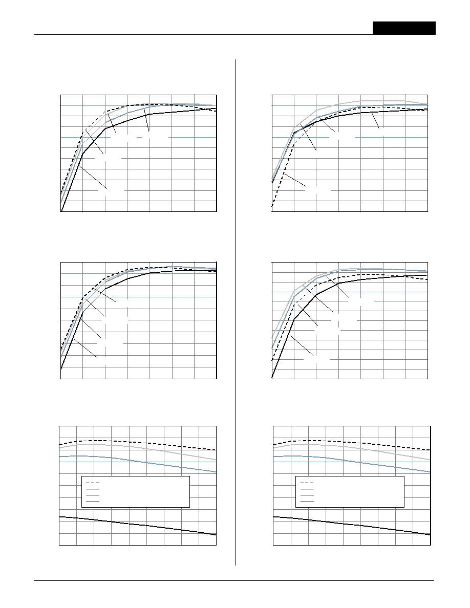
5V Efficiency vs. Load
(+3.3V Output @ 0 Amps.)
V
IN
= 36V
V
IN
= 30V
V
IN
= 24V
V
IN
= 18V
75.0
72.5
70.0
67.5
65.0
62.5
60.0
57.5
55.0
52.5
50.0
1.875
3.75
5.625
7.5
9.375
11.25
13.125
15
+3.3V Output Current (Amps)
Efficienc
y (
%
)
V
IN
= 36V
V
IN
= 18V
V
IN
= 24V
V
IN
= 30V
3.3V Efficiency vs. Load
(+5V Output @ 0 Amps.)
90
88
86
84
82
80
78
76
74
72
70
68
1.875
3.75
5.625
7.5
9.375
11.25
13.125
15
+5V Output Current (Amps)
Efficienc
y (
%
)
V
IN
= 36V
V
IN
= 75V
V
IN
= 60V
V
IN
= 48V
5V Efficiency vs. Load
(+3.3V Output @ 0 Amps)
78
76
74
72
70
68
66
64
62
60
58
56
54
3.3V Efficiency vs. Load
(+5V Output @ 0 Amps.)
1.875
3.75
5.625
7.5
9.375
11.25
13.125
15
+3.3V Output Current (Amps)
Efficienc
y (
%
)
V
IN
= 75V
V
IN
= 48V
V
IN
= 60V
V
IN
= 36V
D24 Model
D48 Model
Typical Performance Curves
11
90
88
86
84
82
80
78
76
74
72
70
36
40.4
44.7
49
53.3
57.7
62
66.3
70.7
75
Input Voltage (Volts)
Efficienc
y (
%
)
Overall Efficiency vs. Line and Load
+3.3V @ 0A and +5V @15A
+3.3V @ 3.75A and +5V @11.25A
+3.3V @ 7.5A and +5V @7.5A
+3.3V @ 15A and +5V @0A
90
88
86
84
82
80
78
76
74
72
70
36
40.4
44.7
49
53.3
57.7
62
66.3
70.7
75
Input Voltage (Volts)
Efficienc
y (
%
)
Overall Efficiency vs. Line and Load
+3.3V @ 0A and +5V @15A
+3.3V @ 3.75A and +5V @11.25A
+3.3V @ 7.5A and +5V @7.5A
+3.3V @ 15A and +5V @0A

7 5 W , D U A L O U T P U T , M I X E D - V O L T A G E D C / D C C O N V E R T E R S
XCP Series
DATEL makes no representation that the use of its products in the circuits described herein, or the use of other technical information contained herein, will not infringe upon existing or future patent rights. The descriptions contained herein do
not imply the granting of licenses to make, use, or sell equipment constructed in accordance therewith. Specifi cations are subject to change without notice. The DATEL logo is a registered DATEL, Inc. trademark.
DATEL (UK) LTD. Tadley, England Tel: (01256)-880444
DATEL S.A.R.L. Montigny Le Bretonneux, France Tel: 01-34-60-01-01
DATEL GmbH M¸nchen, Germany Tel: 89-544334-0
DATEL KK Tokyo, Japan Tel: 3-3779-1031, Osaka Tel: 6-6354-2025
DATEL, Inc. 11 Cabot Boulevard, Mansfi eld, MA 02048-1151
Tel: (508) 339-3000 (800) 233-2765 Fax: (508) 339-6356
Internet: www.datel.com Email: sales@datel.com
ISO 9001 REGISTERED
INNOVATION and EX C ELL E N C E
Æ
Æ
DS-0449 3/02
12
70
60
50
40
30
20
10
Output Ripple and Noise (PARD) vs. Input Voltage
(One output @ 15A, other output @ 0A,
PARD measured on loaded output, 20MHz bandwidth.)
18
20.57
23.14
25.71
28.29
30.86
33.43
36
Input Voltage (Volts)
Output P
ARD
V
olta
g
e
(mVp-p)
PARD 3.3V Output
PARD 5V Output
Ripple 5V Output
Ripple 3.3V Output
60
55
50
45
40
35
30
25
20
15
10
Output Ripple and Noise (PARD) vs. Input Voltage
(One output @ 15A, other output @ 0A,
PARD measured on loaded output, 20MHz bandwidth.)
35
40.71
46.43
52.14
57.86
63.57
69.29
75
Input Voltage (Volts)
Output P
ARD
V
olta
g
e
(mVp-p)
PARD 3.3V Output
PARD 5V Output
Ripple 5V Output
Ripple 3.3V Output
Typical Performance Curves
D24 Model
D48 Model
Options and Adaptations
Optional Functions
The BCP 75W DC/DC Dual Half-Bricks offer various electrical and mechani-
cal options. Per the Ordering Guide on page 2, the trailing input voltage
range (D24 or D48) in each part number pertains to the base part number.
Part-number suffi xes are added after the "input range," indicating the selec-
tion of standard options. The resulting part number is a "standard product"
and is available to any customer desiring that particular combination of
options, as described below.
Suffi x
Description
Blank
On/Off Control function with positive polarity on pin 3 and inde-
pendent trim function on either output (5V trim on pin 5 and 3.3V
trim on pin 8). The pin length remains at 0.2 inches (5.08 mm).
N
On/Off Control function with negative polarity on pin 3.
L1
Trim the pin length to 0.110 ±0.010 inches (2.79 ±0.25mm). This
option requires a 100-piece minimum order quantity.
L2
Trim the pin length to 0.145 ±0.010 inches (3.68 ±0.25mm). This
option requires a 100-piece minimum order quantity.
Adaptations
There are various additional confi gurations available on BCP 75W DC/DC
Dual Half-Brick s. Because designating each of them with a standard
part-number suffi x is not always feasable, DATEL assigns a 5-digit "adapta-
tion code" after the part-number suffi xes. Once a confi guration has been
requested by a customer and created by DATEL, the resulting product is
available to any customer as a "standard" off-the-shelf product. Contact
DATEL directly if you are interested in your own set of options/adaptations.
Our policy for minimum order quantities may apply.
Consequently, the following product is offered for sale:
BCP-5/15-3.3/15-D48-30752
Standard product, 48V
IN
, 5V/15A and 3.3V/15A Outputs with positive On/Off
logic and modifi ed V
OUT
Trim functions (pin 5 and 8 positions) to be compat-
ible with Power-One's HBD-series. Adapted low profi l packaging of 0.5 inches
(12.7 mm) and with trimmed pin length to 0.15 inches (3.8 mm).