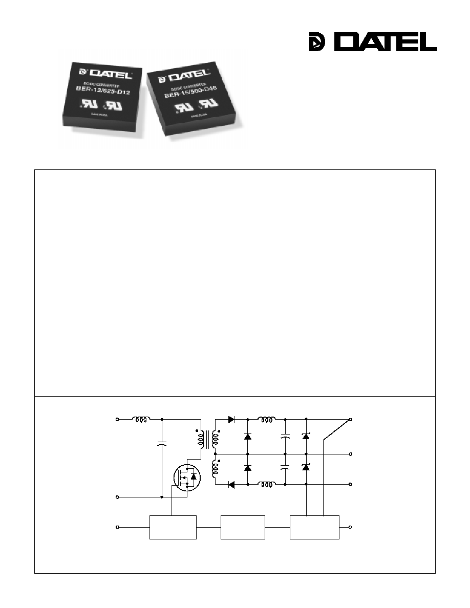
Figure 1. Simplified Schematic
Features
DATEL's BER Model dual-output switching DC/DC converters were designed for
cost-sensitive, moderate-power (15 Watts) applications requiring a reliable, off-the-
shelf solution but not demanding all the high-performance characteristics of DATEL's A-
Series BWR Model converters. Offering slightly wider electrical tolerances and slightly
lower power densities (8.33W/in
3
), BER devices achieve their low cost through the use
of plastic packaging (UL94V-0 rated material) and the exploitation of traditional, yet
highly automated, SMT-on-pcb construction techniques. The result is a contemporary
power converter whose cost/performance/reliability ratio far exceeds the competition.
BER Model DC/DC converters all offer the ultra-wide, 9-to-36V and 18-to-72V, input
voltage ranges that have come to be associated with DATEL power converters.
Output voltages are ±5V, ±12V or ±15V. Line and load regulation are guaranteed not to
exceed ±0.5% and ±1%, respectively. All models incorporate internal input/output
filtering and require no external components for normal operation. All units guarantee
output ripple/noise less than 100mVp-p.
These fully isolated (1000Vdc typical) devices are input overvoltage and reverse-
polarity protected and employ output current limiting to protect both the power con-
verter and its load. They function well in harsh environments and are popular for both
commercial and industrial usage in computer, telecom, aerospace and industrial-control
applications.
The industry-standard, 2" x 2" package size and pinout of the BER Models makes
them ideal replacements for other, more costly, less reliable power converters. They
are equally well suited for original design-ins in systems demanding both low cost and
high reliability.
Low-Cost, Wide-Input-Range
15 Watt, DC/DC Converters
Dual Output
BER Models
+V
IN
≠V
IN
+V
OUT
≠V
OUT
COMMON
PWM
CONTROLLER
REFERENCE &
ERROR AMP
ON/OFF
CONTROL
V
OUT
TRIM
OPTO
ISOLATION
DATEL, Inc., Mansfield, MA 02048 (USA)
∑
Tel: (508)339-3000, (800)233-2765 Fax: (508)339-6356
∑
Email: sales@datel.com
∑
Internet: www.datel.com
INNOVATION and EX C ELL E N C E
Æ
Æ
s
s
s
s
s
s
s
s
s
s
s
s
s
s
s
s
s
s
s
s
s
s
s
s
s
s
s
s
s
s
s
s
s
s
s
s
s
s
s
s
s
s
s
s
s
s
s
s
s
s
s
s
s
s
s
s
Low cost
Rugged, fully potted, diallyl phthalate
plastic packages
Industry-standard form factor (2" x 2")
and pinout
No external components required
±5, ±12 or ±15 Volt outputs
Wide input voltage ranges:
9-36V or 18-72V
Fully regulated (±0.5% line, ±1% load)
Guaranteed efficiencies to 81%
Fully isolated (750Vdc minimum)
and I/O protected
V
OUT
trim and on/off control
UL, CSA, IEC safety approvals
Modifications and customs for OEM's

XER Series
1 5 W , D U A L O U T P U T D C / D C C O N V E R T E R S
2
Function P7
+Input
≠Input
No Pin
On/Off Control
+Output
Common
≠Output
Trim
I/O Connections
Pin
1
2
3
4
5
6
7
8
Typical at T
A
= +25∞C under nominal line voltage and full-load conditions unless otherwise noted.
Ripple/Noise (R/N) measured over a 20MHz bandwidth.
Balanced loads, 20% to 100% load.
Nominal line voltage, no-load/full-load conditions.
Performance Specifications and Ordering Guide
Ripple/Noise
(mVp-p, Max.)
V
OUT
(Volts)
Output
Package
(Case,
Pinout)
Efficiency
(Min.)
Regulation (Max.)
Line
V
IN
Nom.
(Volts)
Range
(Volts)
Model
Input
I
OUT
(mA, Max.)
I
IN
(mA, Max.)
Load
BER-5/1500-D12
±5
±1500
100
±0.5%
±1.0%
24
9-36
45/789
80%
C4, P7
BER-5/1500-D48
±5
±1500
100
±0.5%
±1.0%
48
18-72
25/395
80%
C4, P7
BER-12/625-D12
±12
±625
100
±0.5%
±1.0%
24
9-36
45/779
81%
C4, P7
BER-12/625-D48
±12
±625
100
±0.5%
±1.0%
48
18-72
25/390
81%
C4, P7
BER-15/500-D12
±15
±500
100
±0.5%
±1.0%
24
9-36
45/779
81%
C4, P7
BER-15/500-D48
±15
±500
100
±0.5%
±1.0%
48
18-72
25/390
81%
C4, P7
Nominal Output Voltages:
±5, ±12 or ±15 Volts
Maximum Output Current
in mA from each output
Input Voltage Range:
D12 = 9-36 Volts (24V nominal)
D48 = 18-72 Volts (48V nominal)
Output Configuration:
B = Bipolar
15
B ER
500 D48
-
/
-
Low-Cost, Economy Package
Wide Range Input
BOTTOM VIEW
1.800
(45.72)
0.10
(2.54)
2.00
(50.80)
8
5
6
7
0.40
(10.16)
0.200
(5.08)
0.400
(10.16)
0.100
(2.54)
1
2
4
PLASTIC CASE
INSULATED BASE
0.040 ±0.002 DIA.
(1.016 ±0.051)
2.00
(50.80)
0.20 MIN
(5.08)
0.50
(12.70)
1.200
(30.48)
3 EQ. SP. @
0.400 (10.16)
P A R T N U M B E R S T R U C T U R E
M E C H A N I C A L S P E C I F I C A T I O N S
T E M P E R A T U R E D E R A T I N G
O
u
tp
u
t
P
o
w
e
r (W
a
t
ts
)
Ambient Temperature (∞C)
≠25 0 30 35 40 45 50 55 60 65 70 75 80 85 90
20
19
18
17
16
15
14
13
12
11
10
9
8
7
6
5
4
3
2
1
0
Case C4
BER Models
1 5 W , D U A L O U T P U T D C / D C C O N V E R T E R S
3
Floating Outputs
Since these are isolated DC/DC converters, their outputs are "floating."
Any BER model may be configured to produce an output of 10V, 24V or 30V
(for ±5V, ±12V or ±15V models, respectively) by applying the load across
the +Output and ≠Output pins (pins 5 and 7), with either output grounded.
The Common pin (pin 6) should be left open. Minimum 20% loading is
recommended under these conditions. The total output voltage span may
be externally trimmed as described below.
Filtering and Noise Reduction
All BER 15 Watt DC/DC Converters achieve their rated ripple and noise
specifications without the use of external input/output capacitors. In critical
applications, input/output noise may be further reduced by installing
electrolytic capacitors across the input terminals and/or low-ESR tantalum
or electrolytic capacitors across the output terminals. Output capacitors
should be connected between their respective output pin (pin 5 or 7) and
Common (pin 6) as shown in Figure 2. The caps should be located as close
to the power converters as possible. Typical values are listed below. In
many applications, using values greater than those listed will yield better
results.
In critical, space-sensitive applications, DATEL may be able to tailor the
internal input/output filtering of these units to meet your specific require-
ments. Contact our Applications Engineering Group for additional details.
To Reduce Input Ripple
"D12" Models
20µF, 50V
"D48" Models
20-50µF, 100V
To Reduce Output Ripple
±5V Output
47µF, 10V, Low ESR
±12/15V Outputs
22µF, 20V, Low ESR
Performance/Functional Specifications
Typical @ T
A
= +25∞C under nominal line voltage and full-load conditions, unless noted.
Input
Input Voltage Range:
"D12" Models
9-36 Volts (24V nominal)
"D48" Models
18-72 Volts (48V nominal)
Input Current
See Ordering Guide
Input Filter Type
LC
Overvoltage Shutdown:
"D12 Models"
40 Volts
"D48 Models"
80 Volts
Reverse-Polarity Protection
Yes (Instantaneous, 10A maximum)
On/Off (Sync.) Control (Pin 4)
TTL high = off, low (or open) = on
Output
V
OUT
Accuracy (50% load)
±1%, maximum
Temperature Coefficient
±0.02% per ∞C
Ripple/Noise (20MHz BW)
See Ordering Guide
Line/Load Regulation
See Ordering Guide
Efficiency
See Ordering Guide
Isolation Voltage
750Vdc, minimum
Isolation Capacitance
550pF
Current Limiting
Continuous, auto-recovery
Overvoltage Protection
Zener/transorb clamps, magnetic feedback
Dynamic Characteristics
Transient Response (50% load step)
200µsec max. to ±1.5% of final value
Switching Frequency
160kHz
Environmental
Operating Temperature (ambient):
Without Derating
≠25 to +50∞C
With Derating
to +90∞C (See Derating Curve)
Storage Temperature
≠40 to +100∞C
Physical
Dimensions
2" x 2" x 0.5" (51 x 51 x 12.7mm)
Shielding
None
Case Connection
None
Case Material
Diallyl phthalate, UL94V-0 rated
Pin Material
Brass, solder coated
Weight
2.7 ounces (75.6 grams)
These power converters require a minimum 20% loading to maintain specified regulation.
Operation under no-load conditions will not damage these devices; however they may not
meet all listed specifications.
Application-specific internal input/output filtering can be recommended or perhaps added
internally upon request. Contact DATEL Applications Engineering for details.
Applying a voltage to the Control pin when no input power is applied to the converter can
cause permanent damage to the converter.
Devices can be screened or modified for higher guaranteed isolation voltages.
Contact DATEL Applications Engineering for details.
Devices can be screened for ≠40∞C operation. Contact DATEL Applications Engineering
for details.
Input Voltage:
"D12" Models
44 Volts
"D48" Models
88 Volts
Input Reverse-Polarity Protection
Current must be <10A. Brief
duration only. Fusing recommended.
Output Overvoltage Protection
±5V Outputs
6.8 Volts, limited duration
±12V Outputs
15 Volts, limited duration
±15V Outputs
18 Volts, limited duration
Output Current
Current limited.
Max. currents are
model dependent. Units can
withstand a continuous output
short
on any output for 3 minutes.
Storage Temperature
≠40 to +105∞C
Lead Temperature (soldering, 10 sec.)
+300∞C
These are stress ratings. Exposure of devices to any of these conditions may adversely
affect long-term reliability. Proper operation under conditions other than those listed in the
Performance/Functional Specifications Table is not implied.
Absolute Maximum Ratings
T E C H N I C A L N O T E S
BER Series
4
DS-0327A 7/98
1 5 W , D U A L O U T P U T D C / D C C O N V E R T E R S
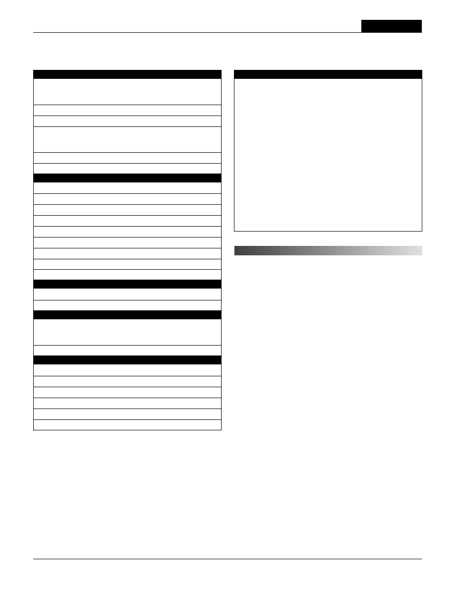
Figure 2. Using External Capacitors to Reduce
Input/Output Ripple/Noise
≠OUTPUT
+INPUT
≠INPUT
+OUTPUT
1
2
5
7
COMMON
6
C
IN
C
OUT
C
OUT
+
+
+
Figure 3a. Trim Connections Using a Trimpot
20k
5-10
Turns
5
7
6
LOAD
LOAD
8
+INPUT
≠INPUT
TRIM
COMMON
≠OUTPUT
+OUTPUT
1
2
+INPUT
≠INPUT
+OUTPUT
TRIM
1
2
5
7
8
LOAD
LOAD
COMMON
6
≠OUTPUT
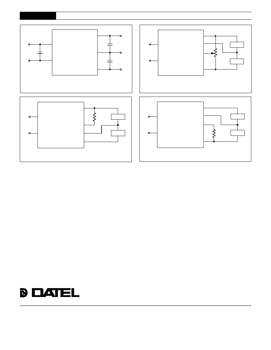
Figure 3b. Fixed-Value Trim Down Resistor
+INPUT
≠INPUT
+OUTPUT
TRIM
1
2
5
7
8
LOAD
LOAD
COMMON
6
≠OUTPUT
Figure 3c. Fixed-Value Trim Up Resistor
Input Fusing
Certain applications and/or safety agencies may require the installation of
fuses at the inputs of power conversion components. For DATEL BER 15
Watt DC/DC Converters, you should use slow-blow type fuses with values no
greater than the following:
V
IN
Range
Fuse Value
"D12"
3A
"D48"
2A
On/Off Control
The On/Off Control pin (pin 4) may be used for remote on/off operation.
A TTL logic high (+2 to +5 Volts, 250µA max.) applied to pin 4 disables the
converter. A TTL logic low (0 to +0.8 Volts, 70µA max.), or no connection,
enables the converter. Control voltages should be referenced to pin 2
(≠Input). Applying a voltage to the Control pin when no input power is
applied to the converter can cause permanent damage to the converter.
Synchronization
In critical applications employing multiple switching DC/DC converters, it
may be desirable to intentionally synchronize the switching of selected
converters (so the system noise can be reduced with notch filtering) or to
purposely desynchronize the converters (to lessen the current-carrying
requirements on intermediate dc buses). For multiple BER DC/DC Convert-
ers, an external clock can be applied to pin 4 (Control) of each device. It
should be a square wave with a maximum 1µsec "high" duration and an
amplitude between +2V and +5V (see On/Off Control) referenced to pin 2
(≠Input). The frequency of the synchronizing clock should be higher than
that of any individual converter. Therefore, it should be 185kHz ±5kHz.
Output Trimming
The total output voltage span, from +Output (pin 5) to ≠Output (pin 7) may
be trimmed ±5% via a single external trimpot or fixed resistor. The trimpot
should be connected as shown in Figure 3a with its wiper connected to pin 8
(Trim). A trimpot can be used to determine the value of a single fixed
resistor which should be connected as shown in Figures 3b and 3c. Connect
the resistor between pin 8 (Trim) and pin 5 (+Output) to trim "down" the
output voltages. Connect the resistor between pins 8 and 7 (≠Output) to trim
"up" the output voltages. Fixed resistors should be metal-film types with
absolute TCR's less than 100ppm/∞C to ensure stability.
DATEL makes no representation that the use of its products in the circuits described herein, or the use of other technical information contained herein, will not infringe upon existing or future patent rights. The descriptions contained herein
do not imply the granting of licenses to make, use, or sell equipment constructed in accordance therewith. Specifications are subject to change without notice. The DATEL logo is a registered DATEL, Inc. trademark.
DATEL (UK) LTD. Tadley, England Tel: (01256)-880444
DATEL S.A.R.L. Montigny Le Bretonneux, France Tel: 01-34-60-01-01
DATEL GmbH M¸nchen, Germany Tel: 89-544334-0
DATEL KK Tokyo, Japan Tel: 3-3779-1031, Osaka Tel: 6-354-2025
DATEL, Inc. 11 Cabot Boulevard, Mansfield, MA 02048-1151
Tel: (508) 339-3000
(800) 233-2765
Fax: (508) 339-6356
Email: datellit@mcimail.com
Data Sheet Fax Back: (508) 261-2857
INNOVATION and EX C ELL E N C E
Æ
Æ
ISO 9001
ISO 9001
R E G I S T E R E D