+INPUT
+OUTPUT
≠INPUT
≠OUTPUT
TRIM
COMMON
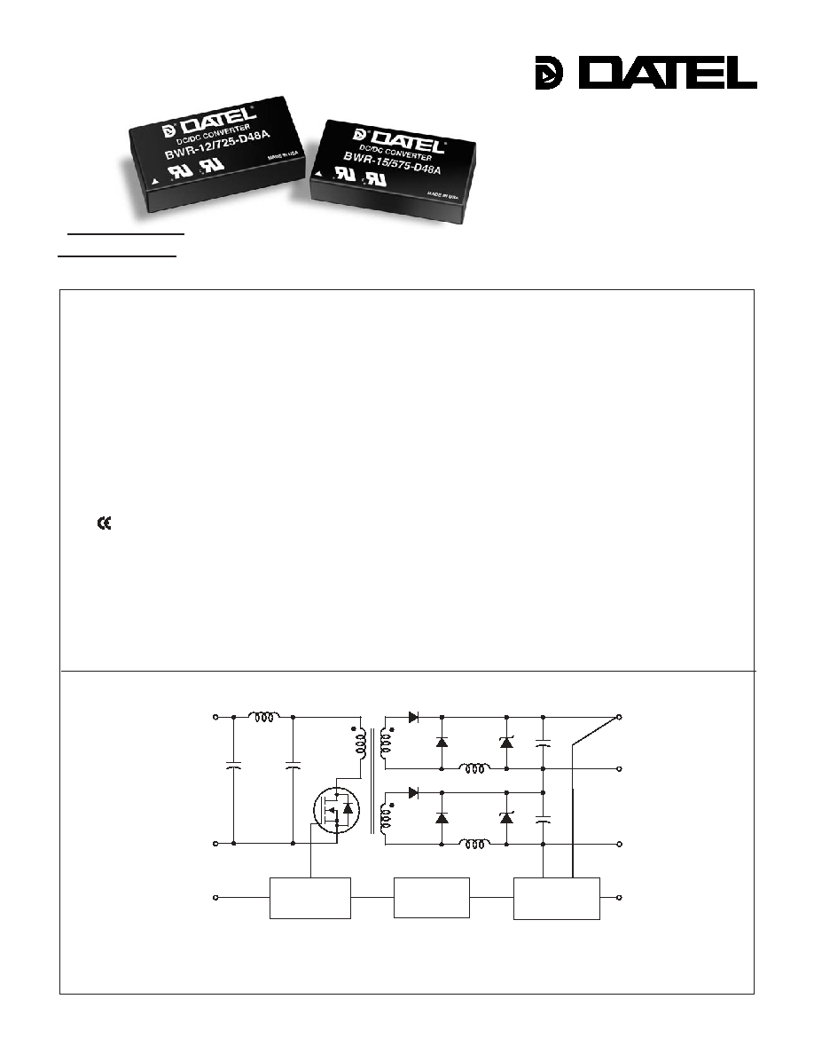
PWM
CONTROLLER
REFERENCE &
ERROR AMP
OPTO
ISOLATION
ON/OFF
CONTROL
(OPTION)
Figure 1. Simplifi ed Schematic
Features
Dual Output
A-Series, BWR Models
High-Reliability, 1" x 2"
15-17 Watt, DC/DC Converters
For your mid-range power requirements, it's hard to beat the combination of
small packaging, low cost, proven reliability and outstanding electrical performance
offered by the 15-17W, dual-output models of DATEL's new A-Series DC/DC convert-
ers. These highly effi cient, rugged converters combine straightforward circuit topolo-
gies, the newest components, proven SMT-on-pcb construction methods, and highly
repeatable automatic-assembly techniques. Their superior durability is substantiated
by a rigorous in-house qualifi cation program that includes HALT (Highly Accelerated
Life Testing).
The input voltage ranges of the BWR 15-17 Bipolar Series (10-18V for "D12A"
models, 18-36V for "D24A" models and 36-75V for "D48A" models) make them
excellent candidates for telecommunication system line drivers, or distributed power
architectures. Their ±5, ±12 or ±15 Volt outputs cover virtually all standard applica-
tions.
These popular power converters are fully isolated (1500Vdc guaranteed) and
display excellent line and load regulation (±0.5% max. for line and load). They are
completely I/O protected (input overvoltage shutdown and reverse-polarity protec-
tion, output current limiting and overvoltage protection) and contain input (pi type)
and output fi ltering to reduce noise.
These extremely reliable, cost-effective power converters are housed in standard
1" x 2" x 0.48" UL94V-0 rated plastic packages. They offer industry-standard pinouts
and are ideally suited for high-volume computer, telecom/datacom, instrumentation
and ATE applications.
INNOVATION and EX C ELL E N C E
Æ
Æ
Output voltages: ±5, ±12 or ±15 Volts
Input voltage ranges:
10-18V, 18-36V or 36-75V
Small packages, 1" x 2" x 0.48"
Industry-standard pinouts
Low cost; Highly reliable
Proven SMT-on-pcb construction
Qual tested; HALT tested; EMC tested
Designed to meet UL60950 and
EN60950
mark available (75V-input models)
Fully isolated, 1500Vdc guaranteed
Guaranteed effi ciencies to 84%
≠40 to +100∞C operating temperature
Modifi cations and customs for OEM's
A - S E R I E S
DATEL, Inc., Mansfi eld, MA 02048 (USA) ∑ Tel: (508)339-3000, (800)233-2765 Fax: (508)339-6356 ∑ Email: sales@datel.com ∑ Internet: www.datel.com
PRELIMINARY
1 5 - 1 7 W , D U A L O U T P U T D C / D C C O N V E R T E R S
A Series
BWR-5/1500-D12A ±5 ±1500 75 100 ±0.5% ±0.5% 12 10-18 35/1524 TBD 83% C14A, P43
BWR-5/1500-D24A ±5 ±1500 75 100 ±0.5% ±0.5% 24 18-36 35/740 82% 84% C14A, P43
BWR-5/1500-D48A ±5 ±1500 75 100 ±0.5% ±0.5% 48 36-75 35/370 83% 85% C14A, P43
BWR-12/725-D12A ±12 ±725 75 100 ±0.5% ±0.5% 12 10-18 35/1710 TBD 85% C14A, P43
BWR-12/725-D24A ±12 ±725 75 100 ±0.5% ±0.5% 24 18-36 35/850 83% 85% C14A, P43
BWR-12/725-D48A ±12 ±725 75 100 ±0.5% ±0.5% 48 36-75 35/420 84% 86% C14A, P43
BWR-15/575-D12A ±15 ±575 75 100 ±0.5% ±0.5% 12 10-18 35/1690 TBD 85% C14A, P43
BWR-15/575-D24A ±15 ±575 75 100 ±0.5% ±0.5% 24 18-36 35/840 84% 86% C14A, P43
BWR-15/575-D48A ±15 ±575 75 100 ±0.5% ±0.5% 48 36-75 35/420 84% 86% C14A, P43
2
1
2
4
5
6
PLASTIC CASE
3
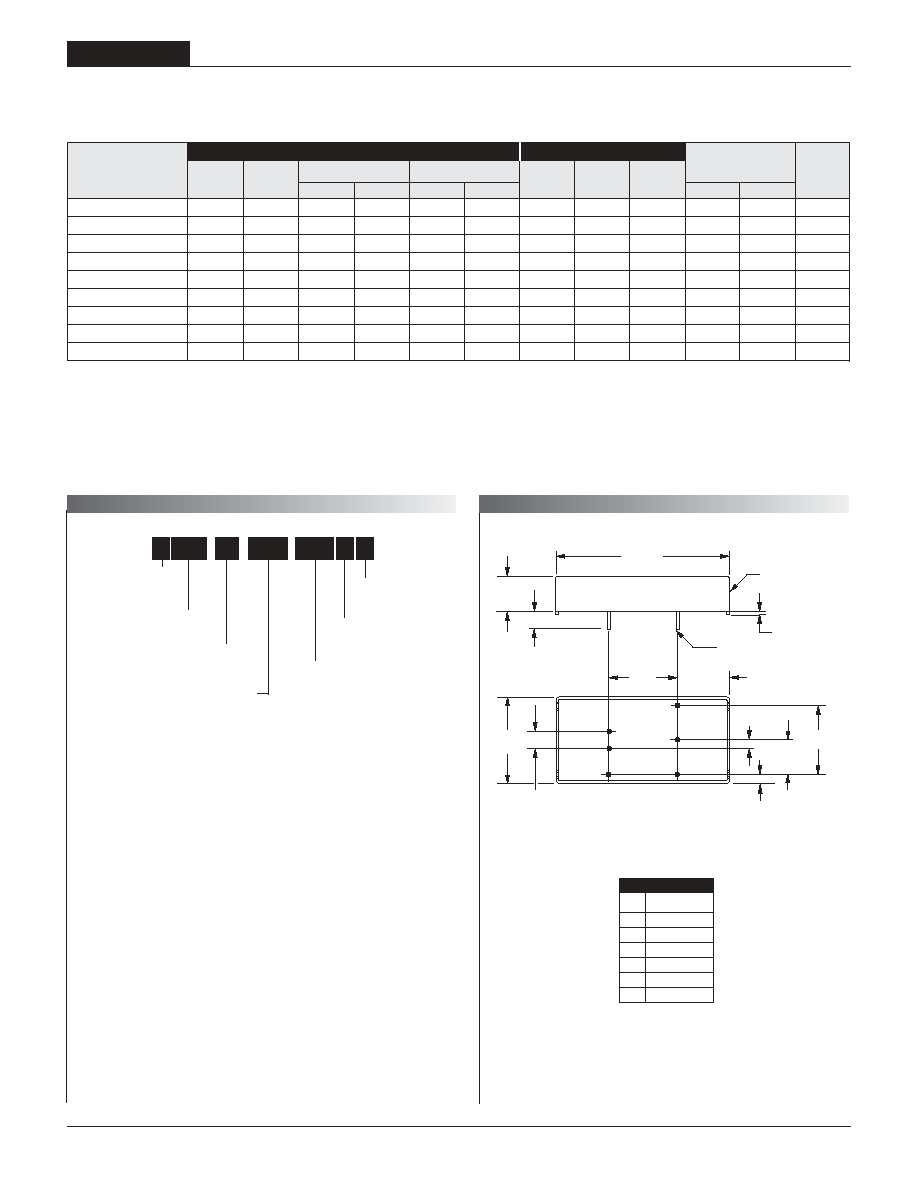
1.00
(25.40)
2.00
(50.80)
0.20 MIN
(5.08)
0.400
(10.16)
0.800
(20.32)
0.800
(20.32)
0.60
(15.24)
0.040 ±0.002 DIA.
(1.016 ±0.051)
BOTTOM VIEW
DIMENSION ARE IN INCHES (MM)
0.200
(5.08)
0.100
(2.54)
0.10
(2.54)
STANDOFF
0.015 (0.38)
0.465
(11.81)
Case C14A
Typical at T
A
= +25∞C under nominal line voltage and full-load conditions unless otherwise noted.
Ripple/Noise (R/N) measured over a 20MHz bandwidth.
Balanced loads, 10% to 100% load.
Nominal line voltage, no-load/full-load conditions.
Nominal Output Voltages:
±5, ±12 or ±15 Volts
Maximum Output Current
in mA from each output
Input Voltage Range:
D12 = 10-18 Volts (12V nominal)
D12 = 18-36 Volts (24V nominal)
D48 = 36-75 Volts (48V nominal)
Wide Range Input
Output Confi guration:
B = Bipolar
12
B WR
725 D48 A
-
/
-
A-Series
High Reliability
Performance Specifi cations and Ordering Guide
I
OUT
(mA)
R/N (mVp-p)
Load
V
OUT
(Volts)
Output
Package
(Case,
Pinout)
Effi ciency
Regulation (Max.)
Line
V
IN
Nom.
(Volts)
Range
(Volts)
Model
Input
I
IN
(mA)
Max.
Typ.
Typ.
Min.
C
Add C or N suffi x as
desired. See below.
P A R T N U M B E R S T R U C T U R E
M E C H A N I C A L S P E C I F I C A T I O N S
Part Number Suffi xes
BWR 15-17 Watt DC/DC's are designed so an On/Off Control function
with either positive polarity ("C" suffi x) or negative polarity ("N" suffi x)
can be added to the pin 3 position. Models ordered without On/Off
control (without C or N suffi x) will not have pin 3 installed.
No Suffi x Pin 3 not installed
C Positive On/Off control function (pin 3)
N Negative On/Off control function (pin 3)
I/O
Connections
Pin Function
P43
1 +Input
2
≠Input
3 On/Off
Control*
4
+Output
5 Output
Return
6
≠Output
* Pin is optional

1 5 - 1 7 W , D U A L O U T P U T D C / D C C O N V E R T E R S
BWR Models
3
Performance/Functional Specifi cations
Typical @ T
A
= +25∞C under nominal line voltage and full-load conditions, unless noted.
All models are specifi ed with no external I/O capacitors.
See Technical Notes/Graphs for details.
Applying a voltage to the On/Off Control (pin 3) when no input power is applied
to the converter can cause permanent damage to the converter.
Output noise may be further reduced with the addition of additional external output capacitors.
See Technical Notes.
The On/Off Control is designed to be driven with open-coolector logic or the application of
appropriate voltage levels. Voltages may be referenced to the ≠Input (pin 2).
Demonstrated MTBF available on request.
For conditions with less than minimum loading, outputs remain stable. However, regulation
performance may degrade.
Input
Input Voltage Range:
D12A Models 10-18 Volts (12V nominal)
D24A Models 18-36 Volts (24V nominal)
D48A Models 36-75 Volts (48V nominal)
Overvoltage Shutdown:
D12A Models 18.5-21 Volts (20V typical)
D24A Models 37-40 Volts (38V typical)
D48A Models 77-81 Volts (79V typical)
Start-Up Threshold:
D12A Models 9.4-9.8 Volts (9.6V typical)
D24A Models 16.5-18 Volts (17V typical)
D48A Models 34-36 Volts (35V typical)
Undervoltage Shutdown:
D12A Models 7-8.5 Volts (8V typical)
D24A Models 15.5-17.5 Volts (17.2V typical)
D48A Models 32.5-35.5 Volts (34.5V typical)
Input Current
Normal Operating Conditions See Ordering Guide
Standby Mode (Off, OV, UV) TBD mA
Input Refl ected Ripple Current 12µH source impedance
20MHz bandwidth, TBD mAp-p
Input Filter Type Pi
Reverse-Polarity Protection Brief duration, 5A maximum.
On/Off Control:
C Models On = open or 13V- +V
IN
, I
IN
= TBD max.
Off = 0-0.8V, I
IN
= TBD max.
N Models On = 0-0.5V, I
IN
= TBD max.
Off = open or TBD- +V
IN
, I
IN
= TBD max.
Output
V
OUT
Accuracy (full load) ±1.0%, maximum
Minimum Loading for Specifi cation 10%
Minimum Loading for Stability No load
Ripple/Noise (20MHz BW) See Ordering Guide
Line/Load Regulation See Ordering Guide
Effi ciency See Ordering Guide
Isolation Voltage 1500Vdc, minimum
Isolation Capacitance 470pF
Isolation Resistance 100M
Current Limit Inception (@ 98% V
OUT
)
±5V Models 1.75-2.25A (2A typical)
±12V Models 0.9-1.1A (1A typical)
±15V Models 0.73-0.93A (0.83A typical)
Average Short-Circuit Current
±5V Models TBD
±12V Models 700mA maximum
±15V Models 700mA maximum
Overvoltage protection Output voltage comparator
±5V Models TBD
±12V Models 13-15.8 Volts
±15V Models 16.2-19.8 Volts
Maximum Capacitive Loading
±5V Models TBD
±12V Models TBD
±15V Models TBD
Temperature Coeffi cient ±0.02% per ∞C
Input Voltage:
Continuous:
D12A Models 23 Volts
D24A Models 42 Volts
D48A Models 81 Volts
Transient (100msec):
D12A Models 50 Volts
D24A Models 50 Volts
D48A Models 100 Volts
On/Off Control (pin 3) Max. Voltages
Referenced to ≠Input (pin 2)
"C" Suffi x +V
IN
"N" Suffi x +7 Volts
Input Reverse-Polarity Protection Current must be <5 Amps. Brief
duration only. Fusing recommended.
Output Current Current limited. Devices can withstand
sustained output short circuits without
damage.
Case Temperature 120∞C
Storage Temperature ≠40 to +120∞C
Lead Temperature (soldering, 10 sec.) +300∞C
These are stress ratings. Exposure of devices to any of these conditions may adversely
affect long-term reliability. Proper operation under conditions other than those listed in the
Performance/Functional Specifi cations Table is not implied.
Absolute Maximum Ratings
Dynamic Characteristics
Transient Response:
(50-100% load step to 2% V
OUT
) 200µsec maximum
Start-Up Time:
V
IN
to V
OUT
TBD
On/Off to V
OUT
TBD
Switching Frequency 300kHz (±30kHz)
Environmental
MTBF Bellcore, ground fi xed, fullpower
25∞C ambient, TBD million hours
Operating Temperature (ambient):
±5V Models TBD
±12V Models TBD
±15V Models TBD
Thermal Shutdown TBD
Storage Temperature ≠40 to +120∞C
Physical
Dimensions 1" x 2" x 0.48" (25.4 x 50.8 x 12.19mm)
Case Material Diallyl Phthalate
Pin Material Brass, solder coated
Weight TBD ounces (TBD grams)
Primary to Secondary Insulation Level Operational
1 5 - 1 7 W , D U A L O U T P U T D C / D C C O N V E R T E R S
A Series
4
Floating Outputs
Since these are isolated DC/DC converters, their outputs are "fl oating," with
respect to the input. As such, it is possible to use +Output, ≠Output or Output
Return as the system ground thereby allowing the fl exibility to generate a
variety of output voltage combinations.
Regulation for BWR 15-17W bipolar converters is monitored between
≠Output and +Output (as opposed to Output to Return).
Minimum Loading Requirements
BWR 15-17W converters employ a classical diode-rectifi cation design topol-
ogy and require a minimum 10% loading to achieve their listed regulation
specifi cations. Operation between no-load and 10% load will result in stable
operation but regulation may degrade.
Filtering and Noise Reduction
All BWR 15-17W DC/DC Converters achieve their rated ripple and noise
specifi cations without the use of external input/output capacitors. In critical
applications, input/output ripple and noise may be further reduced by install-
ing additional external I/O caps. Input capacitors should be selected for bulk
capacitance, low ESR and high rms-ripple current ratings. Input capacitors
serve as energy-storage devices to minimize line voltage caused by transient
IR drops in PCB conductors from backplane to the DC/DC. Ouput capacitors
should be selected for low ESR and appropriate frequency response. All caps
should have appropriate voltage ratings and be mounted as close to the
converters as possible.
The most effective combination of external I/O capacitors will be function of
your particular load and layout conditions. Our Applications Engineers can
recommend potential solutions. Contact our Applications Engineering Group
for additional details.
Input Fusing
Certain applications and/or safety agencies may require the installation of
fuses at the inputs of power conversion components. Fuses should also be
used if the possibility of sustained, non-current-limited, input-voltage polartiy
reversal exists. For DATEL BWR 15-17 Watt DC/DC Converters, you should
use slow-blow type fuses with values no greater than the following:
Model Fuse Value
BWR-5/1500-D12A 4 Amp
BWR-5/1500-D24A 2 Amp
BWR-5/1500-D48A 1 Amp
BWR-12/725-D12A 4 Amp
BWR-12/725-D24A 2.5 Amp
BWR-12/725-D48A 2.5 Amp
BWR-15/575-D12A 4 Amp
BWR-15/575-D24A 2.5 Amp
BWR-15/575-D48A 1 Amp
T E C H N I C A L N O T E S
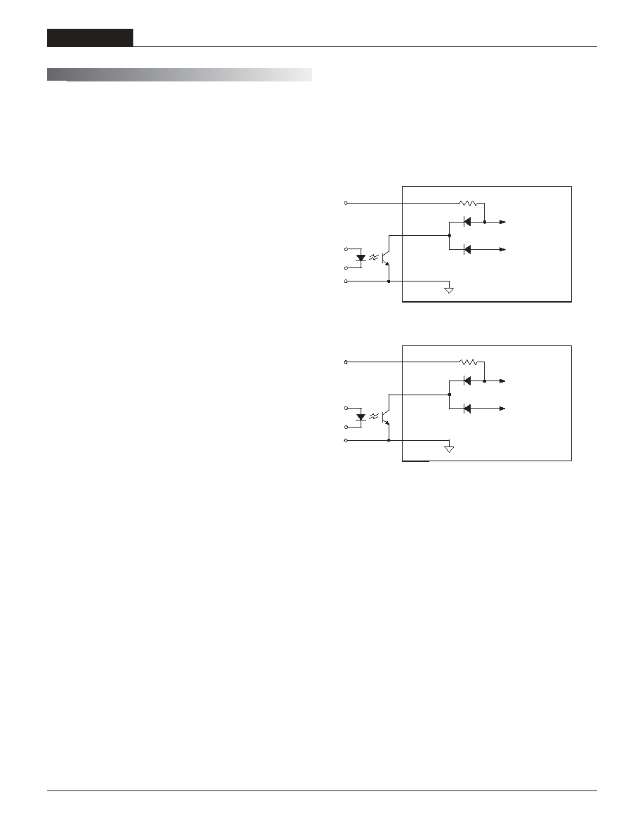
On/Off Control
The input-side, remote On/Off Control function (pin 3) can be ordered to
operate with either polarity. Positive-polarity devices ("C" suffi x) are enabled
when pin 3 is left open or is pulled high (+13V to V
IN
applied with respect to
≠Input, pin 2, (see Figure 2). Positive-polarity devices are disabled when pin
3 is pulled low (0-0.8V with respect to ≠Input). Negative-polarity devices are
off when pin 3 open or pulled high (TBD to V
IN
), and on when pin 2 is pulled
low (0-0.5V). See Figure 3.
Dynamic control of the remote on/off function is best accomplished with
a mechanical relay or an open-collector/open-drain drive circuit (optically
isolated if appropriate). The drive circuit should be able to sink appropriate
current (see Performance Specs) when activated and withstand appropriate
voltage when deactivated.
Applying an external voltage to pin 3 when no input power is applied to the
converter can cause permanent damage to the converter.
3
2
1
+INPUT
13V CIRCUIT
5V CIRCUIT
≠INPUT
ON/OFF
CONTROL
3
2
1
+INPUT
13V CIRCUIT
5V CIRCUIT
≠INPUT
ON/OFF
CONTROL
Figure 2. Driving the Positive Polarity On/Off Control Pin
Figure 3. Driving the Negative Polarity On/Off Control Pin

1 5 - 1 7 W , D U A L O U T P U T D C / D C C O N V E R T E R S
BWR Models
5
Sync Function (Optional)
Contact DATEL for further information.
Start-Up Time
The V
IN
to V
OUT
start-up time is the interval of time where the input voltage
crosses the turn-on threshold point, and the fully loaded output voltage
enters and remains within its specifi ed accuracy band. Actual measured
times will vary with external output capacitance and load. The BWR
15-17W Series implements a soft start circuit that limits the duty cycle
of the PWM controller at power up, thereby limiting the Input Inrush current.
The On/Off Control to V
OUT
start-up time assumes the converter has its
nominal input voltage applied but is turned off via the On/Off Control pin.
The specifi cation defi nes the interval between the time at which the converter
is turned on and the fully loaded output voltage enters and remains within
its specifi ed accuracy band. Similar to the V
IN
to V
OUT
start-up, the On/Off
Control to V
OUT
start-up time is also governed by the internal soft start
circuitry and external load capacitance.
Input Overvoltage/Undervoltage Shutdown and Start-Up Threshold
Under normal start-up conditions, devices will not begin to regulate until the
ramping-up input voltage exceeds the Start-Up Threshold Voltage (35V for
"D48" models). Once operating, devices will not turn off until the input volt-
age drops below the Undervoltage Shutdown limit (34V for "D48" models).
Subsequent re-start will not occur until the input is brought back up to the
Start-Up Threshold. This built in hysteresis prevents any unstable on/off
situations from occurring at a single input voltage.
Input voltages exceeding the input overvoltage shutdown specifi cation listed
in the Performance/Functional Specifi cations will cause the device to shut-
down. A built-in hysteresis of 0.6 to 1.6 Volts for all models will not allow the
converter to restart until the input voltage is suffi ciently reduced.
Current Limiting
When output power increases to 16% to 52% of the rated output current,
the DC/DC converter will go into a current limiting mode. In this condition
the output voltage will decrease proportionately with increases in output cur-
rent, thereby maintaining a somewhat constant power dissipation. This is
commonly referred to as power limiting. Current limit inception is defi ned
as the point where the full-power output voltage falls below the specifi ed
tolerance. See Performance/Functional Specifi cations. If the load current
being drawn from the converter is signifi cant enough, the unit will go into a
short circuit condition. See "Short Circuit Condition."
Short Circuit Condition
When a converter is in current limit mode the output voltages will drop as
the output current demand increases. If the output voltage drops too low, the
magnetically coupled voltage used to develop primary side voltages will also
drop, thereby shutting down the PWM controller.
Following a time-out period, the PWM will restart, causing the output volt-
ages to begin ramping to their appropriate values. If the short-circuit condi-
tion persists, another shutdown cycle will be initiated. This on/off cycling is
referred to as "hiccup" mode. The hiccup cycling reduces the average output
current, thereby preventing internal temperatures from rising to excessive
levels. The BWR 15-17W Series is capable of enduring an indefi nite short
circuit output condition.
Thermal Shutdown
These BWR converters are equipped with Thermal Shutdown Circuitry. If
environmental conditions cause the internal temperature of the DC/DC con-
verter rises above the designed operating temperature, a precision tem-
perature sensor will power down the unit. When the internal temperature
decreases below the threshold of the temperature sensor the unit will self
start. See Performance/Functional Specifi cations.
Output Overvoltage Protection
The output voltage is monitored for an overvoltage condition via magnetic
coupling to the primary side. If the output voltage rises to a fault condition,
which could be damaging to the load circuitry (see Performance Specifi ca-
tions), the sensing circuitry will power down the PWM controller causing the
output voltage to decrease. Following a time-out period the PWM will restart,
causing the output voltage to ramp to its appropriate value. If the fault
condition persists, and the output voltages again climb to excessive levels,
the overvoltage circuitry will initiate another shutdown cycle. This on/off
cycling is referred to as "hiccup" mode.
Trimming Output Voltages
Load Regulation
Regulation for the BWR 15-17W bipolar converters is monitored between
≠Output and +Output (as opposed to Output to Return). As such regulation
will assure that voltage between ≠Output and +Output pins remains within
the V
OUT
accuracy listed in the Performance/Functional Specifi cations table.
If loading from +/≠ Outputs to Output Return is symmetrical, the voltage
at Output pins with respect to Output Return will also be symmetrical. An
unbalance in loading will consequently result in a degraded V
OUT
regulation
accuracy from +/≠ Outputs to Output Return ( ≠Output to +Output regulation
will still be within specifi cation). Figure 4 shows output accuracy effects of
unbalanced loading.
Chang
e in
V
OUT
to Output Return (%V
OUT
)
Load Imbalance as % of Output Current, Max.
1.4
1.2
1
0.8
0.6
0.4
0.2
0
0
10
20
30
40
50
60
70
80
90
Figure 4. Output Voltaage Accuracy vs. Imbalanced Loading
PRELIMINAR
Y