5V and 3.3V, Independent Dual Output
30 Watt, DC/DC Converters
Dual Output
Mixed Voltage, BWR Models
Features
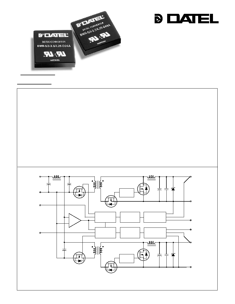
Figure 1. Simplifi ed Schematic
INNOVATION and EX C ELL E N C E
Æ
Æ
!
!
!
!
!
!
!
!
!
!
!
DATEL, Inc., Mansfi eld, MA 02048 (USA) ∑ Tel: (508)339-3000, (800)233-2765 Fax: (508)339-6356 ∑ Email: sales@datel.com ∑ Internet: www.datel.com
DATEL's BWR series of DC/DC converters now includes two independent con-
verters in one 2" x 2" package. The BWR-5/3-3.3/4.25 family provides both 5V at 3
Amps and 3.3V at 4.25 Amps for a combined output power of 30 Watts from input
ranges of 10V to 18V (-D12A), 18 to 36V (-D24A), or 36 to 75V (-D48A).
Each output is regulated by its own control loop to provide ±1% load and ±0.5%
line regulation. Individual trim pins and a negative or positive on/off control pin
allow independent adjustment of output voltages and any combination of power-on
sequencing between the 5V and 3.3V outputs. A high effi ciency of 88% allows full
load operation up to +65∞C ambient temperature in a still air environment. Although
functionally independent, both outputs are driven from synchronized PWMs to
prevent asynchronously generated beat frequencies.
Housed in a plastic case, all models include input Pi fi ltering, input overvoltage
protection, independent output short circuit and current limiting protection and
independent output overvoltage protection as well as thermal shutdown. These
devices meet IEC950, UL1950 and EN6950 safety standards. CB reports are
available upon request. "D48A" models are CE marked (meet LVD requirements).
Independently regulated 5V/ 3.3V outputs
5V @ 3A/3.3V @ 4.25A simultaneously
delivered
Independent V
OUT
Trim pins for margining
Independent On/Off Control pins
88% effi ciency; 75mV ripple/noise
Input ranges: 10-18V, 18-36V or 36-75V
UL 1950 and EN60950 safety approvals
Fully isolated, 1500Vdc guaranteed
Input under and overvoltage shutdown
Independent OVP; short circuit protection
Thermal shutdown
≠INPUT
(2)
PWM
CONTROLLER
OPTO
ISOLATION
REFERENCE &
ERROR AMP
SWITCH
CONTROL
+3.3V OUTPUT
(9)
+3.3V OUTPUT
RETURN
(8)
SWITCH
CONTROL
+5V OUTPUT
RETURN
(6)
+5V OUTPUT
(5)
+5V TRIM
(7)
+3.3V TRIM
(10)
+INPUT
(1)
5V ON/OFF
CONTROL
(3)
3.3V ON/OFF
CONTROL
(4)
INPUT UNDERVOLTAGE
AND OVERVOLTAGE
COMPARATORS
PWM
CONTROLLER
OPTO
ISOLATION
REFERENCE &
ERROR AMP
A - S E R I E S
3 0 W , D U A L O U T P U T , M I X E D - V O L T A G E D C / D C C O N V E R T E R S
A-Series
1
2
3
4
8
9
10
5
6
7
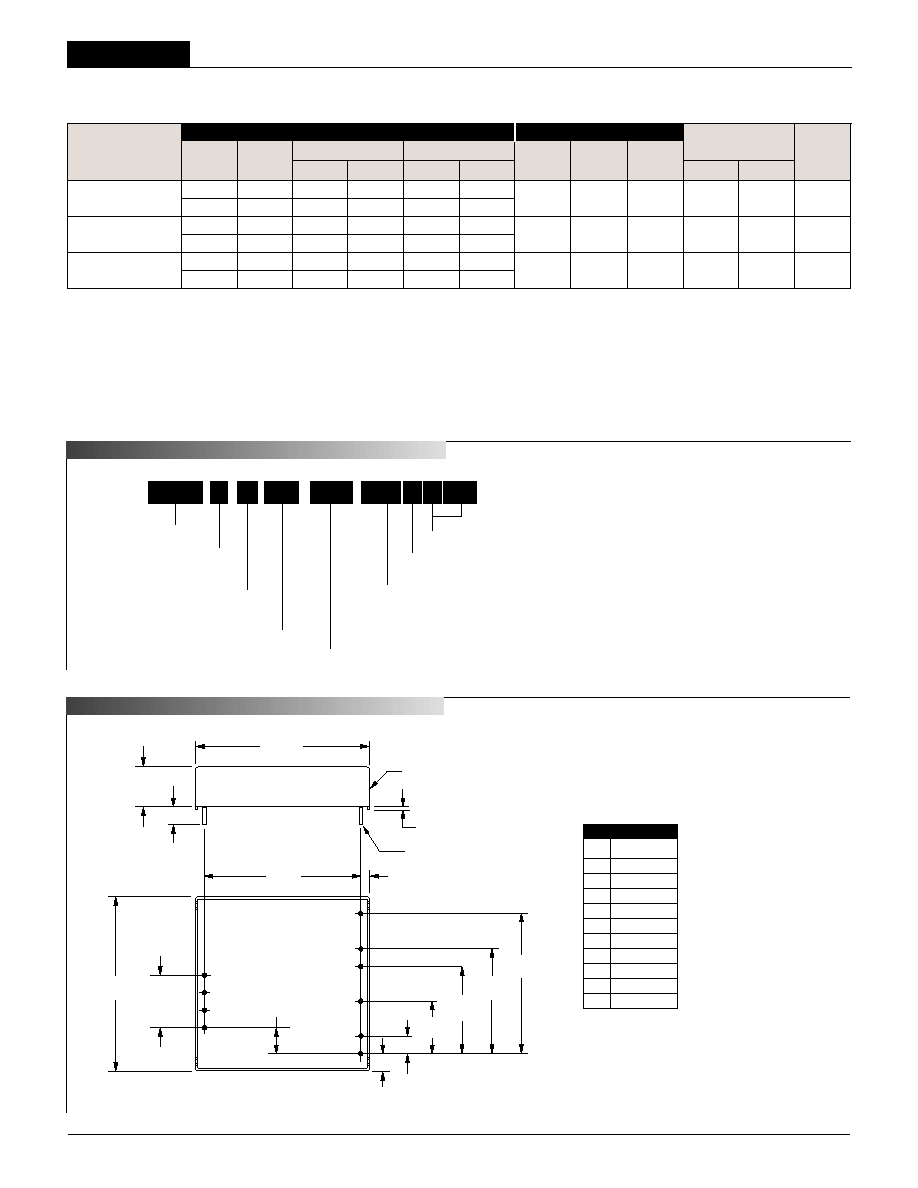
2.00
(50.80)
1.800
(45.72)
0.10
(2.54)
BOTTOM VIEW
0.20
(5.08)
0.200
(5.08)
0.300
(7.62)
0.600
(15.24)
1.000
(25.40)
1.600
(40.64)
1.200
(30.48)
0.600
(15.24)
3 EQ. SP. @
0.200 (5.08)
PLASTIC CASE
0.040 ±0.001 DIA.
(1.016 ±0.025)
0.20 MIN
(5.08)
2.00
(50.08)
0.48
(12.19)
STANDOFF
0.020 (0.51)
DIMENSIONS ARE IN INCHES (MM)
Performance Specifi cations and Ordering Guide
P A R T N U M B E R S T R U C T U R E
V
1
Nominal Output Voltage:
5 Volts
5
BWR
3
-
/
D48
-
Input Voltage Range:
D12A = 10-18 Volts (12V nominal)
D24A = 18-36 Volts (24V nominal)
D48A = 36-75 Volts (48V nominal)
I
1
Maximum Output Current:
3 Amps
Dual Output/
Mixed-Voltage Series
3.3
4.25
/
-
N
V
2
Nominal Output Voltage:
3.3 Volts
I
2
Maximum Output Current:
4.25 Amps
Optional Functions
Optional Functions
BWR 30 Watt DC/DC's are designed so a negative logic
on/off control ("N" suffi x) can be added in the pins 3 and 4 position.
Blank
Standard product. No options specifi ed.
N Negative polarity on/off control
L1 Pin length: 0.110 in. (2.79mm) ±0.010
L2 Pin length: 0.145 in. (3.68mm) ±0.010
Refer to the last page for additional options.
BWR-5/3-3.3/4.25-D12A
5 3 75 100 ±0.5%
±1%
12 10-18 210/2846 83% 85% C20, P42
3.3 4.25 75 100 ±0.5%
±1%
BWR-5/3-3.3/4.25-D24A
5 3 75 100 ±0.5%
±1%
24 18-36 115/1374 85.5% 88% C20, P42
3.3 4.25 75 100 ±0.5%
±1%
BWR-5/3-3.3/4.25-D48A
5 3 75 100 ±0.5%
±1%
48 36-75 70/687 85.5% 88% C20, P42
3.3 4.25 75 100 ±0.5%
±1%
Typical at T
A
= +25∞C under nominal line voltage and "full-load" conditions.
Any combination of 5V/3.3V current, not to exceed the published I
OUT
specifi cation (30 Watts).
Ripple/Noise (R/N) measured over a 20MHz bandwidth with 0.47µF ceramic output capacitors.
Tested from 10% load to 100% load.
Nominal line voltage, no load/full load condition.
Output
Input
R/N (mVp-p)
Regulation
(Max.)
Effi ciency
Package
V
OUT
I
OUT
V
IN
Nom.
Range
I
IN
(Case,
Model
(Volts) (Amps) Typ. Max. Line Load
(Volts) (Volts) (mA) Min. Typ. Pinout)
2
I/O
Connections
Pin Function
P42
1 +Input
2
≠Input
3
+5V
On/Off
4 +3.3V
On/Off
5
+5V
Output
6
+5V
Return
7
+5V
Trim
8 +3.3V
Return
9 +3.3V
Output
10
+3.3V
Trim
Case C20
M E C A N I C A L S P E C I F I C A T I O N S
LX
A
A-Series
High Reliability
BWR Models
3 0 W , D U A L O U T P U T , M I X E D - V O L T A G E D C / D C C O N V E R T E R S
Performance/Functional Specifi cations
Typical @ T
A
= +25∞C under nominal line voltage, balanced "full-load" conditions, unless noted.
Input
Input Voltage Range:
D12A Models 10-18 Volts (12V nominal)
D24A Models 18-36 Volts (24V nominal)
D48A Models 36-75 Volts (48V nominal)
Overvoltage Shutdown:
D12A Models 18.5-21 Volts (20V nominal)
D24A Models 37-40 Volts (38V typical)
D48A Models 77-81 Volts (79V typical)
Start-Up Threshold:
D12A Models 9.4-10 Volts (9.6V typical)
D24A Models 16.5-18 Volts (17V typical)
D48A Models 34-36 Volts (35V typical)
Undervoltage Shutdown:
D12A Models 7-8.5 Volts (8V typical)
D24A Models 16-17.5 Volts (16.5V typical)
D48A Models 32.5-34.5 Volts (33.5V typical)
Input Current:
Normal Operating Conditions See Ordering Guide
Standby Mode:
Off, OV, UV, Thermal Shutdown 10mA typical
Input Refl ected Ripple Current:
Source Impedance <0.1
, no external input fi ltering
D12A Models TBD
D24A/D48A Models TBD
Internal Input Filter Type Pi (0.022µF - 4.7µH - 2.46µF)
Reverse-Polarity Protection:
D12A Models 1 minute duration, 6A maximum
D24A Models 1 minute duration, 4A maximum
D48A Models 1 minute duration, 2A maximum
On/Off Control (Pins 3 & 4):
D12A, D24A & D48A Models On = open or 13V to +V
IN
,
I
IN
= 1.6mA @ 13V
Off = 0-0.8V, I
IN
= 2mA @ 0V
"N" Suffi x Models
On = 0-1.2V, I
IN
= 2mA @ 0V
Off = open.
Output
V
OUT
Accuracy
5V Output ±1.5% maximum
3.3V Output ±1.5% maximum
Minimum Loading Per Specifi cation 10% of I
OUT
maximum
Minimum Loading For Stability
No load
Ripple/Noise (20MHz BW)
See Ordering Guide
Line/Load Regulation See Ordering Guide
Effi ciency See Ordering Guide
Trim Range
±5%
Isolation Voltage:
Input-to-Output 1500Vdc minimum
Isolation Resistance 100M
Isolation Capacitance 470pF
Current Limit Inception:
5V @ 98.5% V
OUT
3.8-5.1 Amps
3.3V @ 98.5% V
OUT
5.4-6.8 Amps
Short Circuit Current:
5V Output 3.0 Amps average current
3.3V Output 3.0 Amps average current
Output (continued)
Overvoltage Protection: Magnetic feedback, transorb
5V Output 6.0 Volts
3.3V Output 4.1 Volts
Maximum Capacitive Loading
D12A Models 3.3V 1000µF
5V
680µF
D24A, D48A Models 3.3V 1000µF
5V 680µF
Temperature Coeffi cient ±0.02% per ∞C
Dynamic Characteristics
Dynamic Load Response:
5V (50-100% load step to 1% V
OUT
) 200µsec maximum
3.3V (50-100% load step to 1% V
OUT
) 200µsec maximum
Start-Up Time:
V
IN
to V
OUT
10ms
On/Off to V
OUT
TBD
Switching Frequency 355kHz (±35kHz)
Environmental
MTBF
Bellcore, ground fi xed, full power
25∞C ambient
D12A Models 873.9 thousand hours
D24A Models 1.32 million hours
D48A Models 1.23 million hours
Operating Temperature (Ambient):
Without Derating:
D12A Models ≠40 to +60∞C
D24A & D48A Models ≠40 to +65∞C
With Derating To +100∞C (See Derating Curves)
Case Temperature:
Maximum Operational +100∞C
For Thermal Shutdown +100∞C minimum, +110∞C maximum
Storage Temperature ≠40 to +120∞C
Physical
Dimensions 2" x 2" x 0.5" (50.8 x 50.8 x 12.7mm)
Case Material Diallyl phthalate, UL94V-0 rated
Pin Material Brass, solder coated
Weight: 2.7 ounces (76.5 grams)
Primary to Secondary Insulation Level Operational
All models are specifi ed with external 0.47µF ceramic output capacitors.
See Technical Notes/Graphs for details.
Applying a voltage to On/Off Control (pins 3 & 4) when no input power is applied to the
converter can cause permanent damage.
Output noise may be further reduced with the installation of additional external output
capacitors. See Technical Notes.
On/Off control is designed to be driven with open collector or by appropriate voltage
levels. Voltages must be referenced to the ≠Input (pin 2).
Demonstrated MTBF available on request.
For conditions with less than minimum loading, outputs remain stable. However, regulation
performance will degrade.
Maximum applied voltage to On/Off pin (N suffi x) less than 19.0V.
3

3 0 W , D U A L O U T P U T , M I X E D - V O L T A G E D C / D C C O N V E R T E R S
A-Series
Output P
o
wer (watts)
Ambient Temperature (
∞C)
35
30
25
20
15
10
5
0
≠40
≠10
0
10
20
30
40
50
60
70
80
90
100
Output Power vs. Ambient Temperature
(V
IN
nominal, natural convection air flow.)
D12A MODELS
D24A, D48A
MODELS
Typical Performance Curves
Absolute Maximum Ratings
Input Voltage:
Continuous:
D12A Models 23 Volts
D24A Models 42 Volts
D48A Models 81 Volts
Transient (100msec): D12A Models 25 Volts
D24A Models 50 Volts
D48A Models 100 Volts
Input Reverse-Polarity Protection Input Current must be limited. 1 minute
duration. Fusing recommended.
D12A Models
6 Amps
D24A Models
4 Amps
D48A Models
2 Amps
Output Current
Current limited. Devices can withstand
an indefi nite output short circuit.
On/Off Control (Pins 3 & 4) Max. Voltages
Referenced to ≠Input (pin 2)
D12A, D24A & D48A Models +V
IN
"N" Models
±19V
Storage Temperature
≠40 to +120∞C
Lead Temperature (Soldering, 10 sec.) +300∞C
These are stress ratings. Exposure of devices to any of these conditions may adversely
affect long-term reliability. Proper operation under conditions other than those listed in the
Performance/Functional Specifi cations Table is not implied, nor recommended.
T E C H N I C A L N O T E S
Trimming Output Voltages
These BWR converters have a trim capability (pins 3 & 4) that allow users
to independently adjust the output voltages ±5%. Adjustments to the output
voltages can be accomplished via a trim pot, Figure 2, or a single fi xed
resistor as shown in Figures 3 and 4. A single fi xed resistor can increase
or decrease the output voltage depending on its connection. Fixed resistors
should have absolute TCR's less than 100ppm/∞C to minimize sensitivity to
changes in temperature.
A single resistor connected from the 5V Trim pin (pin 7) to the +5V Output
(pin 5), see Figure 3, will decrease the +5V output voltage. A resistor con-
nected from the +5V Trim (pin 7) to the +5V Return (pin 6) will increase the
+5V output voltage. See Figure 4.
Similarly, the 3.3V output can be adjusted using a single resistor connected
from the +3.3V Trim (pin 10) to the +3.3V Output (pin 9) or to the +3.3V
Return (pin 8). See Figures 3 and 4.
+5V
LOAD
+5V OUTPUT
≠INPUT
+5V
ON/OFF
CONTROL
+3.3V
ON/OFF
CONTROL
+INPUT
+5V TRIM
+5V RETURN
+3.3V OUTPUT
+3.3V TRIM
+3.3V RETURN
10
8
1
4
9
7
5
6
20k
5-22
TURNS
3
2
+3.3V
LOAD
20k
5-22
TURNS
+5V LOAD
5V R
TRIM DOWN
+5V OUTPUT
≠INPUT
+5V
ON/OFF
CONTROL
+3.3V
ON/OFF
CONTROL
+INPUT
+5V TRIM
+5V RETURN
+3.3V TRIM
+3.3V OUTPUT
+3.3V RETURN
9
8
1
4
10
7
5
6
3
2
+3.3V LOAD
3.3V R
TRIM DOWN
+5V LOAD
5V R
TRIM UP
+5V OUTPUT
≠INPUT
+5V
ON/OFF
CONTROL
+3.3V
ON/OFF
CONTROL
+INPUT
+5V TRIM
+5V RETURN
+3.3V TRIM
+3.3V OUTPUT
+3.3V RETURN
9
8
1
4
10
7
5
6
3
2
+3.3V LOAD
3.3V R
TRIM UP
4
Note: Resistor values are in k
. Accuracy of adjustment is subject to
tolerances of resistors and factory-adjusted output accuracy.
V
O
= desired output voltage.
UP
V
O
≠ 5
5V R
T
(k
) =
≠15
6.27
UP
V
O
≠ 3.3
3.3V R
T
(k
) =
≠14.3
3.16
DOWN
5 ≠ V
O
5V R
T
(k
) =
≠15
2.49(V
O
≠ 2.52)
DOWN
3.3 ≠ V
O
3.3V R
T
(k
) =
≠14.3
2.49(V
O
≠ 1.27)
Figure 2. Trim Connections Using A Trim Pot
Figure 3. Trim Connections To Decrease Output Voltages Using Fixed Resistors
Figure 4. Trim Connections To Increase Output Voltages Using Fixed Resistors

BWR Models
3 0 W , D U A L O U T P U T , M I X E D - V O L T A G E D C / D C C O N V E R T E R S
Typical Performance Curves
Typical Start-Up from V
IN
(V
IN
= nominal, 5V @ 3A/3.3V @ 4.25A, 0.47µF output capacitors.)
5V
OUT
V
IN
3.3V
OUT
2.5msec/div
87
85
83
81
79
77
75
D12A Models: Efficiency vs. Line and Load
10
11.14
12.29
13.43
14.57
15.71
16.86
18
Line Voltage (Volts)
Efficienc
y (
%
)
5V@0A, 3.3V@4.25A
5V@3A, 3.3V@0A
5V@3A, 3.3V@4.25A
89
88
87
86
85
84
83
82
81
80
79
D24A Models: Efficiency vs. Line and Load
18
24
30
36
Line Voltage (Volts)
Efficienc
y (
%
)
5V@3A, 3.3V@2.325A
5V@1.65A, 3.3V@4.25A
5V@3A, 3.3V@0.4A
5V@0.3A, 3.3V@4.25A
89
87
85
83
81
79
77
D48A Models: Efficiency vs. Line and Load
36
48
60
75
Line Voltage (Volts)
Efficienc
y (
%
)
5V@3A, 3.3V@2.325A
5V@1.65A, 3.3V@4.25A
5V@3A, 3.3V@0.4A
5V@0.3A, 3.3V@4.25A
5